Page 80 of 331

�µ�µ
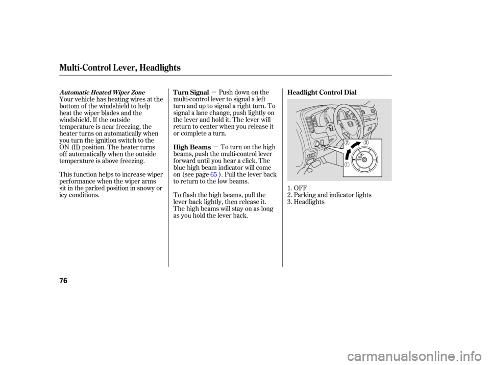
OFF
Parking and indicator lights
Headlights
Push
down on the
multi-control lever to signal a left
turn and up to signal a right turn. To
signal a lane change, push lightly on
the lever and hold it. The lever will
return to center when you release it
or complete a turn.
To turn on the high
beams, push the multi-control lever
fo rward until you hear a click. The
blue high beam indicator will come
on (see page ). Pull the lever back
to return to the low beams.
To f lash the high beams, pull the
lever back lightly, then release it.
The high beams will stay on as long
as you hold the lever back.
Your vehicle has heating wires at the
bottom of the windshield to help
heat the wiper blades and the
windshield. If the outside
temperature is near f reezing, the
heater turns on automatically when
you turn the ignition switch to the
ON (II) position. The heater turns
of f automatically when the outside
temperature is above f reezing.
This f unction helps to increase wiper
perf ormance when the wiper arms
sit in the parked position in snowy or
icy conditions.
1.
2.
3.
65 Headlight Control Dial
Turn Signal
High Beams
Automatic Heated Wiper Zone
Multi-Control L ever, Headlights
76
Page 172 of 331

The direction and center position
icons come on when you turn the
ignition switch to the ON (II)
position. The system then begins to
check the vehicle direction and
illuminates the appropriate icon(s).The compass can be af f ected by
driving near power lines or stations,
across bridges, through tunnels,
over railroad crossings, past large
vehicles, or driving near large
objects that cause magnetic
interference. It can also be affected
by accessories such as antennas and
roof racks that are mounted by
magnets.
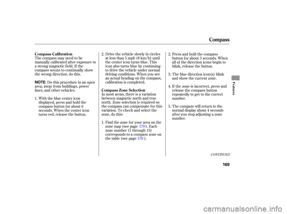
Your vehicle has a compass in the
rear view mirror. The compass
indicates the vehicle direction with
illuminated letters; N (north), S
(south), W (west), and E (east). The
center blue icon in the compass is
always on. It serves as a ref erence
point.
To turn the compass on or of f , press
the compass button on the back of
the rear view mirror.The compass mirror has a light
sensor behind the right side of the
rear view mirror. Make sure the
extended sun visor or an accessory is
not covering the sensor.
If equipped
Compass Function
Compass
168
COMPASS
BUTTON
CENTER ICON
REAR VIEW MIRROR
Page 173 of 331

The compass may need to be
manually calibrated after exposure to
a strong magnetic field. If the
compassseemstocontinuallyshow
the wrong direction, do this. Drivethevehicleslowlyincircles
at
less than 5 mph (8 km/h) until
the center icon turns blue. This
icon also turns blue by continuing
to drive the vehicle under normal
driving conditions. When you see
an actual heading on the compass,
calibration is completed.
In most areas, there is a varia tion
between magnetic north and true
north. Zone selection is required so
the compass can compensate for this
varia tion. To check and select the
zone, do this:
Find the zone for your area on the
zone map (see page ). Each
zone number (1 through 15)
co rresponds to a compass zone on
the table (see page ). Press and hold the compass
button f or about 3 seconds. When
all of the direction icons begin to
blink, release the button.
The blue direction icon(s) blink
and show the current zone.
If the zone is incorrect, press and
release the compass button
repeatedly to get to the correct
number.
The compass will return to the
normal display about 4 seconds
af ter you stop adjusting a zone
number.
Do this procedure in an open
area, away f rom buildings, power
lines, and other vehicles.
With the blue center icon
displayed, press and hold the
compass button for about 6
seconds. When the center icon
turns red, release the button. 2.
1. 2.
3.
4.
1. 5.
170
170
CONT INUED
Compass Calibration
Compass Zone Selection
Compass
Features
169
NOTE:
Page 221 of 331

There are two common types of
trailer brakes: surge and electric.
Surge brakes are common f or boat
trailers, since the brakes will get wet.
If you choose electric brakes, be
sure they are electronically actuated.
Do not attempt to tap into your
vehicle’s hydraulic system. No
matter how successf ul it may seem,
any attempt to attach trailer brakes
to your vehicle’s hydraulic system
will lower braking ef f ectiveness and
create a potential hazard.
Seeyourtrailermanufacturerfor
more inf ormation on installing
electric brakes. Honda requires that any trailer with
a total trailer weight of 1,000 lbs (455
kg) or more have its own brakes.A f actory installed, 4-pin gray
connector is located under the
instrument panel near the top of the
parking brake pedal. This connector
has all of the circuits required to
install most electric trailer brake
controllers. A jumper harness to
adapt your electric trailer brake
controller to the vehicle is included
with the optional Genuine Honda
trailer hitch kit. To obtain a trailer
hitch kit, see your dealer.
Have a qualif ied mechanic install
your trailer brake controller
f ollowing the trailer brake controller
manuf acturer’s instructions. Failure
to properly install the trailer brake
controller may increase the distance
it takes f or you to stop your vehicle
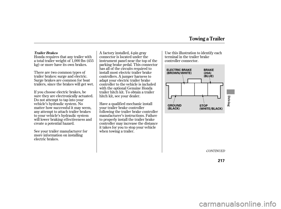
when towing a trailer.Use this illustration to identif y each
terminal in the trailer brake
controller connector.
CONT INUED
Trailer Brakes
Towing a Trailer
Driving
217
BRAKE
(20A)
(BLUE)
GROUND
(BLACK)
ELECTRIC BRAKE
(BROWN/WHITE)
STOP
(WHITE/BLACK)
Page 223 of 331
�´
Trailer lights and equipment must
comply with f ederal, state, province,
and local regulations. Check trailer
light requirements f or the areas
where you plan to tow, and use only
equipment designed f or your vehicle.Since lighting and wiring vary with
trailer type and brand, you should
also have a qualif ied mechanic install
a suitable connector between the
vehicle and the trailer.
Your vehicle is equipped with a
connector to install an optional trailer
lighting connector that mates with
your vehicle. We recommend that you have your
dealer install a Honda wiring harness
and converter. This harness has
been designed f or your vehicle. Ref er to the above illustration f or
wiring information.
Trailer Lights
Towing a Trailer
Driving
219
GROUND
(BLACK)
LEFT TURN SIGNAL
AND BRAKE LIGHTS
(GREEN/WHITE)
TAILLIGHTS
(GREEN/BLACK)
ELECTRIC BRAKE
(BROWN/WHITE) RIGHT TURN SIGNAL
AND BRAKE LIGHTS
(GREEN/RED)
BACK-UP LIGHTS
(BLUE)
GROUND
(BLACK)
B CHARGE
(GREEN)
Page 227 of 331
�´
Refer to the above illustrations for
wiring information. The
trailer jumper harness is used to
install the controller for the electric
trailer brakes. For more information,
see on page . 217
Towing a Trailer
T railer Connect or Socket s
Trailer Brakes
T railer Jumper Harness
Driving
223
7-PIN TRAILER SOCKET
ELECTRIC
BRAKE
(BLUE)
SMALL
LIGHT
(GREEN)
B
CHARGE
(BLACK)
BACK LIGHT
(YELLOW)
GROUND
(WHITE)
4-PIN TRAILER SOCKETGROUND
(WHITE)
GROUND
(BLACK)ELECTRIC BRAKE
(BROWN/WHITE)
BRAKE LIGHTS
(WHITE/BLACK)
BRAKE
(20A)
(WHITE)
LEFT TURN/
STOP
(YELLOW)
RIGHT TURN/
STOP
(GREEN)
SMALL LIGHTS
(BROWN)
RIGHT
TURN/
STOP
(BROWN)
LEFT
TURN/
STOP
(RED)
Page 249 of 331
�Î
�Î
Fluid Locations
Maint enance
245
ENGINE OIL DIPSTICK
(Orange loop)
WASHER FLUID
(Blue cap)RADIATOR CAP AUTOMATIC
TRANSMISSION
FLUID DIPSTICK
(Yellow loop)
BRAKE FLUID
(Gray cap)
ENGINE
COOLANT
RESERVOIR POWER STEERING
FLUID (Red cap) ENGINE OIL FILL CAP
: Under the gray cover