Page 956 of 1226
303-1 4-32 Electronic Engine Controls 303-1 4-32
REMOVAL AND INSTALLATION
Crankshaft Position (CKP) Sensor
General Equipment A~i~hten the M6 x 18 mm bolt finger-tight L,. '
2. Remove the splash shield
I ~olt, ~6 x 18 mm
CKP alignment tool
3. CAUTIONS: only.
Rotate the crankshaft pulley clockwise until
A0nly turn the crankshaft pulley in the
normal direction of rotation. the
crankshaft pulley timing bolt,
M6 x 18
I. Raise and support the vehicle.
mm can be installed through the crankshaft
For additional information, refer to: Lifting pulley
timing hole into the engine front cover.
(1 00-02, Description and Operation).
4. Remove the components in the order
indicated in the following
illustration(s) and
2006.0 Fiesta 1212006 ~423211 en
procarmanuals.com
Page 960 of 1226
303-1 4-36 Electronic Engine Controls 303-1 4-36
REMOVAL AND INSTALLATION
Ifem 2 Coolant hose kern 3 KS
I. Detach the coolant hose from the coolant N0TE:Make a note of the position of the KS and
hose retaining clip and position it to one
when installed.
make sure
it is positioned in the same position
.
side.
Installation Details
ltem 3 KS
NOTE: Prior to installing the KS, clean the engine
block and KS mating surfaces.
N0TE:Make sure the KS is installed in the same
position as removed.
(I.
2006.0 Fiesta 1212006 G426587en
procarmanuals.com
Page 964 of 1226
Automatic Transmission/Transaxle -
Vehicles With: 4-Speed Automatic
Transmission
(AW81-40)
SPECIFICATIONS
Transmission range (TR) sensor to selector shaft 7 -
locking nut
I Transmission range (TR) sensor retaining bolts I 5 I - I 44 I
I Manual shift lever retaining nut I 13 I 10 I - I
2006.0 Fiesta 1212006 G371496en
procarmanuals.com
Page 973 of 1226

Automatic Transmission/Transaxle -
Vehicles With: 4-Speed Automatic
307-01 -1 3 Transmission (AW81-40) 307-01 -1 3
DESCRIPTION AND OPERATION
Internal gearshift mechanism
Item Description The movement is then transferred via the selector
1
2
I I I The cone displaces the parking pawl when the
The mechanical parking lock secures the vehicle
selector lever position wPw is against rolling away.
The parking pawl engages in the teeth on the
When the vehicle is stationary it is engaged purely
output wheel of the planetary gearset. mechanically via the selector lever when the
selector lever position "P" is engaged. Accordingly,
the differential is blocked via the
intermediate shaft, and the vehicle is secured and
The movement of the selector lever is transmitted
cannot roll away. via the selector lever cable to the selector shaft Stepped cam
with actuating lever for the
3
4
lever. Selector
shaft
2006.0 Fiesta 1212006 G380521 en
shaft to the stepped cam.
forms part of the stepped cam, and it is used to
actuate the manual selector slide in the main
Actuating rod for the parking pawl with cone
Parking pawl
manual
selector slide
control body.
The actuating rod for the parking pawl with cone
is hooked into the stepped cam.
The actuating lever for
the manual selector slide
procarmanuals.com
Page 993 of 1226

Automatic Transmission/Transaxle -
Vehicles With: 4Speed Automatic
307-01 -33 Transmission (AW81-40) 307-01 -33
DESCRIPTION AND OPERATION
This is influenced by the following variables: Vehicle
speed,
Engine load, Transmission fluid temperature.
Accelerator pedal position, The following are actuated:
Transmission input speed, SSA shift solenoid valve,
Vehicle speed,
Transmission fluid temperature,
Selector lever position.
The
following are actuated:
Main
regulating valve.
Reverse gear safety strategy
SSB shift solenoid valve.
Torque reduction when pulling away
In order to protect the clutches against excessively
high torque when pulling away, the PCM reduces
the engine torque in response to a request from
the transmission
control.
If the accelerator pedal is depressed while the
The transmission control unit prevents shifts into vehicle is pulling away, then the transmission reverse gear while the vehicle is driving forwards, control unit sends a corresponding signal as otherwise serious transmission damage can be requesting a torque reduction via the CAN databus. caused.
The reverse gear safety strategy is active when This
is influenced by the
following variables:
reverse gear is engaged with the selector lever at ' Selector lever position,
vehicle speeds in excess of 11 kmlh. Accelerator pedal position,
In this
case the transmission control unit actuates ' Engine speed,
the shift timing solenoid valve, as a result of which Transmission input speed,
the actuating pressure does not reach the reverse
. Vehicle speed. gear clutch or the reverse gear brake.
The following are actuated:
The reverse gear safety strategy is deactivated
PCM (torque reduction request signal via the
when the vehicle speed is below 9 kmlh. The
actuating pressure can then reach the reverse gear CAN
databus).
clutch and the reverse gear brake and the gearshift
into reverse gear is performed.
Selector lever positions
This is influenced by the following variables:
Vehicle speed,
Selector lever position.
The
following are actuated:
Shift timing solenoid valve.
Selector lever position "P"
No gear is engaged in selector lever position "P".
The parking
pawl is engaged manually via the
selector lever cable and the selector shaft.
Avoidance of gearshift judder during
engagement of a transmission range Selector
lever position "R"
In order to prevent gearshift judder when moving The reverse gear is eWaged in selector lever
the selector lever from N to D, the transmission position "R.
control unit initially shifts into
2nd gear instead of
1 st gear, and then immediately shifts back into I st
gear before the gearshift process is finished. Selector lever position "N"
This reduces the amount of gearshift judder during No gear is engaged in selector lever position WNW. engagement of a forward drive range.
The powertrain is not blocked. This is influenced by the following variables:
Selector lever position,
Accelerator pedal position,
Transmission input speed,
2006.0 Fiesta 1212006 G380530en
procarmanuals.com
Page 1000 of 1226

Automatic Transmission/Transaxle -
Vehicles With: 4-Speed Automatic
307-01 -40 Transmission (AW81-40)
307-01 -40
DESCRIPTION AND
OPEMION
Driver's side door ajar switch
The door ajar switch is located in the door lock on
the driver's side.
When the door is closed a ground connection is
signalled to the transmission control unit.
When the door is opened this ground connection
is interrupted.
The transmission control unit uses the signal from
the driver's side door ajar switch to warn the driver
if the selector lever is not in position
"P" and the
driver's door is open.
In this case the transmission control unit transmits
the warning tone request via the CAN
databus to
the instrument cluster.
The instrument cluster passes this request on to
the GEM, which then generates a warning tone.
Consequences of signal failure:
no warning tone request.
Actuators
Main regulating valve
Item Description
I 1 I Main regulating valve I
The main regulating valve is a proportional valve
which converts the applied electric current into a
proportional hydraulic pressure.
The currentless state corresponds to maximum
pressure.
/
The main regulating valve is used to determine the
main line pressure and therefore the actuating
pressure for the clutches and brakes.
Consequences of signal failure:
hydraulic emergency running mode.
SSA and SSB shift solenoid valves
Item Description
2006.0 Fiesta 1212006 G380530en
1
2
SSA
SSB
(- t..
procarmanuals.com
Page 1003 of 1226

Automatic Transmission/Transaxle -
Vehicles With: 4-Speed Automatic
307-01 -43 Transmission (AW81-40) 307-01 -43
DESCRIPTION AND OPERATION
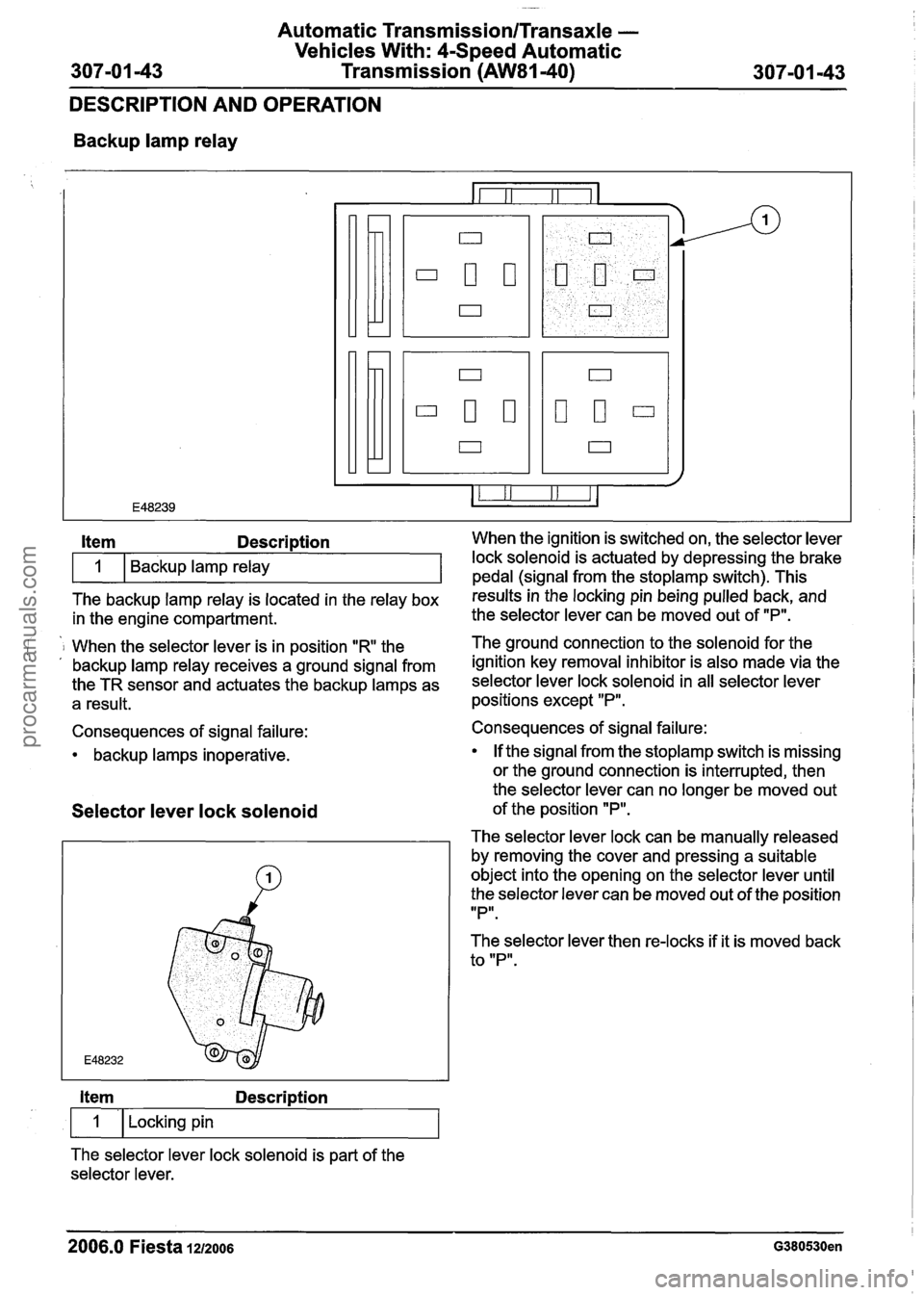
Backup lamp relay
The backup lamp relay is located in the relay box results inthe locking pin being pulled back, and
in the engine compartment. the
selector lever can be moved out of "P".
Item Description When the ignition is switched on, the selector lever
i 1 When the selector lever is in position "R the The ground connection to the solenoid for
the . , backup lamp relay receives a ground signal from ignition key removal inhibitor is also made via the
the TR sensor and actuates the backup lamps as selector lever lock solenoid in all selector lever
a result. positions except "P".
1
Consequences of signal failure:
backup lamps inoperative. Backup lamp relay
Selector
lever lock solenoid
lock solenoid is actuated by depressing the brake
pedal (sianal from the stoplamp switch). This
Item Description
1 I Locking pin
The selector lever lock solenoid is part of the
selector lever. Consequences of signal failure:
If the signal from the
stoplamp switch is missing
or the ground connection is interrupted, then
the selector lever can no longer be moved out
of the position
"P".
The selector lever lock can be manually released
by removing the cover and pressing a suitable
object into the opening on the selector lever until
the selector lever can be moved out of the position
IIPlr.
The selector lever then re-locks if it is moved back
to "P".
2006.0 Fiesta 1212006 G380530en
procarmanuals.com
Page 1004 of 1226

Automatic Transmission/Transaxle -
Vehicles With: 4-Speed Automatic
307-01
-44 Transmission (AW81-40) 307-01 -44
DESCRIPTION AND OPERATION
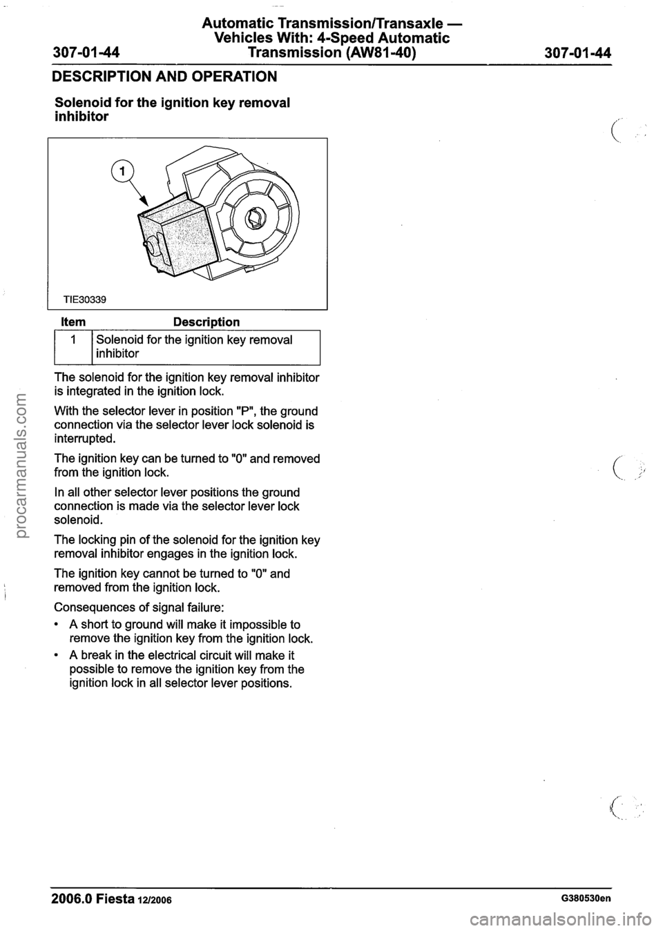
Solenoid for the ignition key removal
inhibitor
Solenoid for the ignition key removal
inhibitor
The solenoid for the ignition key removal inhibitor
is integrated in the ignition lock.
With the selector lever in position
"P", the ground
connection via the selector lever lock solenoid is
interrupted.
The ignition key can be turned to
"0" and removed
from the ignition lock.
In all other selector lever positions the ground
connection is made via the selector lever lock
solenoid.
The locking pin of the solenoid for the ignition key
removal inhibitor engages in the ignition lock.
The ignition key cannot be turned to
"0" and
removed from the ignition lock.
Consequences of signal failure:
A short to ground will make it impossible to
remove the ignition key from the ignition lock.
A break in the electrical circuit will make it
possible to remove the ignition key from the
ignition lock in all selector lever positions.
2006.0 Fiesta 12/2006 G380530en
procarmanuals.com