Page 97 of 146
96IN AN EMERGENCY
3) change bulb B-fig. 30 by pressing
a 12V-5W bulb into the holder. THIRD BRAKE LIGHT
To replace one or more 12V-5W
bulbs:
1) loosen the five screws A-fig. 31
and remove the complete covering;
2) disconnect the connection B-
fig. 32and loosen the three screws
C fastening the light cluster;
3) loosen the four screws D-fig. 33
and separate the bulb unit from the
lens;4) change the burnt bulb E-fig. 34.
Press into place;
5) refit the unit reversing the oper-
ations described above.
fig. 31
P4Q00117
fig. 30
P4Q00116
fig. 32
P4Q00118
fig. 34
P4Q00120
fig. 33
P4Q00119
083-104 Seicento GB 22-11-2007 10:50 Pagina 96
Page 98 of 146
 in the event of a fail-
ure or improper")
97IN AN EMERGENCY
IF AN INTERIOR
LIGHT BURNS OUT IF A FUSE BLOWS
A fuse is an element for protecting
the electrical system. A fuse will trip
(i.e. it will blow) in the event of a fail-
ure or improper interventions in the
electrical system.
If an electrical device is not working,
check whether the respective fuse is
blown. The conductor should be in-
tact. If it is not, replace the fuse with
another with the same amperage
(same colour) fig. 37.
A- Undamaged fuse.
B - Fuse with broken filament. Modifications or repairs
to the electrical system
carried out incorrectly
and without bearing the features
of the system in mind can cause
malfunctions with the risk of fire. COURTESY LIGHT
To replace the 12V-5W bulb use a
screwdriver as a lever at the points in-
dicated by the arrows and remove the
complete pressure-fit light unit
fig. 35.
BOOT LIGHT
To replace the 12V-5W ceiling light
bulb, remove the clipped on lens with
a screwdriver as shown in fig. 36.
fig. 35
P4Q01029
fig. 37
P4Q00089
fig. 36
P4Q01053
083-104 Seicento GB 22-11-2007 10:50 Pagina 97
Page 99 of 146
98IN AN EMERGENCY
Never change a fuse
with another amperage:
fire risk !To locate the fuse, refer to the table
on the following pages. Do not attempt to re-
pair a blown maxi fuse.
Go to a Fiat Dealership.
If the fuse blows again,
have the car inspected at
a Fiat Dealership.
fig. 38
P4Q00121
fig. 39
P4Q01030
Remove the blown use with the
tongs Cwhich can be found in the
fusebox.
Never replace a broken
fuse with anything other
than a new fuse. Always
use a fuse of the same colour.
Before changing a fuse,
check the ignition key has
been removed and that
all the other electric devices have
been turned off/disabled. FUSE LOCATION
The fusebox is located to the left of
the steering wheel. To reach the fuse-
box, loosen the screw B-fig. 38 fas-
tening the cover A.
The numbers indicating the devices
corresponding to the fuses are shown
on the back of the cover fig. 39.
083-104 Seicento GB 22-11-2007 10:50 Pagina 98
Page 100 of 146

99IN AN EMERGENCY
An additional 7.5A fuse is located by
the side of the climate control system.
It can be reached from inside the pas-
senger compartment under the dash-
board.
Fuses in the engine
compartment
A fusebox is located on the left side
of the engine compartment behind the
battery. It contains four high amper-
age fuses A-fig. 40 (MAXI FUSES)
which act as additional fire protection
in preventing high intensity cables
from overheating the following :
A- 30A - injection control unit.
B- 40A - Ignition switch.
C- 30A - engine cooling fan.D- 60A -dashboard fusebox
power.
IMPORTANT Go directly to a
Fiat Dealershipto have any one of
these four fuses restored.
Other version-specific fuses are
arranged next to the four MAXI fuses.
They protect the following devices:
E - 30A - climate control sys-
tem.
F - 30A - optional power cir-
cuits.
G - 40A - electrical power
steering system.
H - 60A - ABSA fusebox B-fig. 41 containing other
three fuses is located in the engine
compartment on the right-hand side.
To reach the fuses, loosen the two
nuts A and remove the cover B.
Fuses fig. 42 protect:
1 - 7.5A -Fiat CODE and control
unit (+30)
2 - 15A -injection system auxiliary
units and climate control
system auxiliary units
3 - 7.5A -Fiat CODE and elec-
tronic injection control
unit (15/54)
fig. 40
P4Q01031
fig. 41
P4Q01032
fig. 42
P4Q01033
083-104 Seicento GB 22-11-2007 10:50 Pagina 99
Page 101 of 146

100IN AN EMERGENCY
System/Component Fuse no. Amperage Location
Front left-hand sidelight
Front right-hand sidelight
Left-hand taillight
Right-hand taillight
Left-hand dipped beam headlight
Right-hand dipped beam headlight
Left-hand main beam headlight
Right-hand main beam headlight
Left-hand brake light
Right-hand brake light
Additional brake light
(3rdbrake light)
Left-hand number plate light
Right-hand number plate light
Reversing light
Rear foglight
Hazard lights
Direction indicators
Front foglights
Ceiling light
Windscreen wiper/washer
Horn
Electric windows
Door locking system
Heated rear window
Cigar lighter
5 10A fig. 39
4 10A fig. 39
4 10A fig. 39
5 10A fig. 39
6 10A fig. 39
7 10A fig. 39
8 10A fig. 39
9 10A fig. 39
21 10A fig. 39
21 10A fig. 39
21 10A fig. 39
4 10A fig. 39
5 10A fig. 39
21 10A fig. 39
18 10A fig. 39
16 10A fig. 39
22 10A fig. 39
19 15A fig. 39
15 15A fig. 39
25 20A fig. 39
17 15A fig. 39
2 25A fig. 39
1 15A fig. 39
14 20A fig. 39
24 25A fig. 39
System/Component Fuse no. Amperage Location
6 10A fig. 39
22 10A fig. 39
9 10A fig. 39
13 20A fig. 39
20 20A fig. 39
15 15A fig. 39
11 20A fig. 39
23 10A fig. 39
3 10A fig. 39
1 7,5A fig. 42
1 7,5A fig. 42
E 30A fig. 40
C 30A fig. 40
24 25A fig. 39
3 7.5A fig. 42
3 7.5A fig. 42
F 30A fig. 40
2 15A fig. 42
2 15A fig. 42
B 40A fig. 40
12 7.5A fig. 39
15 15A fig. 39
10 10A fig. 39Headlight beam adjuster
Instrument panel (+15)
Main beam headlight warning light
Stalks: light control
Stalks: general
Sound system + battery
Sunroof
Airbag system
ABS (+15)
Fiat CODE system (+30)
Injection control unit (+30)
Climate control system
Engine cooler radiator fan
Passenger compartment fan
Electronic ignition
injection system (+15)
Fiat CODE system (+15)
Optional device power circuits
Electronic injection sensors
Climate control system auxiliary units
Ignition switch
Relay coil power
Instrument panel (+30)
Electrical power steering system
(+15)
083-104 Seicento GB 22-11-2007 10:50 Pagina 100
Page 102 of 146

101IN AN EMERGENCY
JUMP STARTING
See
JUMP STARTINGin this chapter.
IF THE BATTERY
IS FLAT
First of all, read the CAR MAINTE-
NANCEchapter for the steps to be
taken to avoid the battery running
down and to ensure it has a long life.
RECHARGING THE BATTERY
You are advised to recharge the bat-
tery slowly for a period of approxi-
mately 24 hours at a low amperage.
Charging for too long could damage
the battery.
Proceed as follows:
1)Disconnect the electric system
from the battery terminals.
IMPORTANTWhere relevant,
switch the electronic car alarm off
with the remote control.3)Turn on the charger.
4)When you have finished, turn the
charger off before disconnecting the
battery.
5)Reconnect the cables to the bat-
tery terminals. Make sure the polarity
is correct.
The liquid in the battery
is poisonous and corro-
sive. Do not let it touch
the skin or eyes. Recharging the
battery should be done in a well-
ventilated area away from naked
flames or possible sources of
sparks: explosion and fire risk. Do not attempt to
recharge a frozen bat-
tery. Thaw is first other-
wise it could explode. If the bat-
tery froze, make sure the inter-
nal elements are not broken
(short-circuit risk) and that the
casing is not cracked (risk of
spilling the poisonous and corro-
sive liquid).
Under no circumstances
should a battery charger
be used to start the en-
gine: it could damage the elec-
tronic systems and in particular
the ignition and injection control
units.
083-104 Seicento GB 22-11-2007 10:50 Pagina 101
Page 103 of 146

102IN AN EMERGENCY
JACKING THE CAR
WITH THE JACK
See
IF A TYRE IS PUNCTUREDin this
chapter. Please note:
– The jack requires no adjustments.
– The jack cannot be repaired. If it
breaks it must be replaced with a new
jack.
– Apart from the handle shown in
this chapter no other tools should be
installed on the jack. WITH A SHOP JACK
From the front
Jack up the car only by positioning
the jack arm at the gearbox/differen-
tial and placing a rubber pad in be-
tween, as shown in fig. 43.
From the rear end
The car may only be raised by plac-
ing the jack arm under the suspension
supports with a flat, compact piece of
wood placed as shown in fig. 44. The jack should only be
used to change a wheel
on the car for which it
was designed. It should not be
put to other uses or employed to
raise other models. Under no cir-
cumstances should it be used
when carrying out repairs under
the car.
An incorrectly posi-
tioned jack may cause the
car to fall. Do not use the
jack to lift loads exceeding that
indicated on the label attached
to the jack itself. Never start the engine
when the car is jacked up.
Detach the trailer,
where relevant, before jacking up
the car.
fig. 43
P4Q00136
fig. 44
P4Q00137
083-104 Seicento GB 22-11-2007 10:50 Pagina 102
Page 104 of 146

103IN AN EMERGENCY
Before starting to tow,
turn the ignition key to
MAR and then to STOP.
Do not remove the key. If the
key is removed, the steering lock
engages automatically which pre-
vents the wheels being turned.
While the car is being
towed with the engine
off, remember that the
brake pedal and steering will re-
quire more effort as you no
longer have the benefit of the
power brakes and power steer-
ing. Do not use flexible cables to
tow. Avoid jerking. Whilst tow-
ing, ensure that the coupling to
the vehicle does not damage the
surrounding components.
The car can be lifted
from the side providing
the hydraulic jack arm is
fitted with a special bracket in
the plate housing.
WITH AN ARM HOIST
Jack up the car by arranging the ends
of the arms in the areas shown in
fig. 45.
IF THE CAR NEEDS
TO BE TOWED
A tow hitch is provided with the car.
To fasten the tow hitch:
1)Take the tow eye from the spare
wheel in the boot.
When towing the car,
you must comply with
the specific traffic regula-
tions regarding the tow hitch and
how to tow on the road.
fig. 45
P4Q00138
From the side
083-104 Seicento GB 22-11-2007 10:50 Pagina 103
 1
1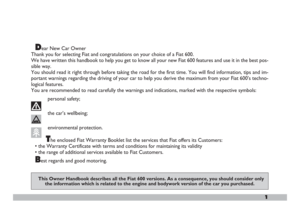 2
2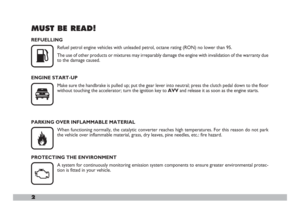 3
3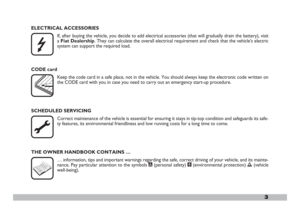 4
4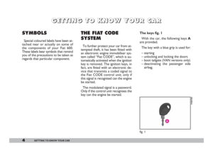 5
5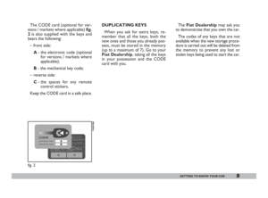 6
6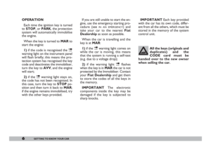 7
7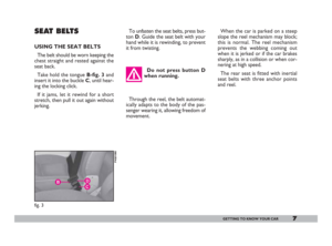 8
8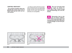 9
9 10
10 11
11 12
12 13
13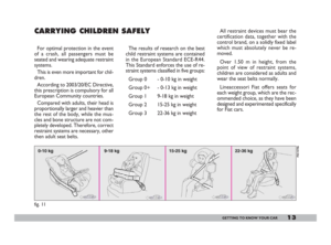 14
14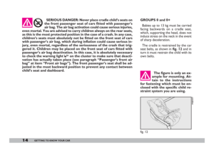 15
15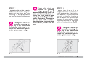 16
16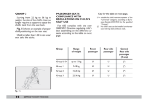 17
17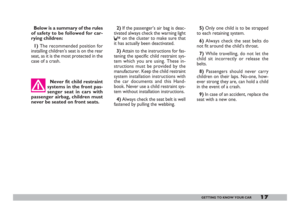 18
18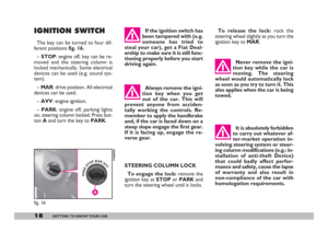 19
19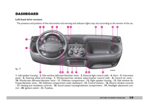 20
20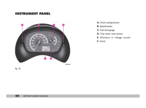 21
21 22
22 23
23 24
24 25
25 26
26 27
27 28
28 29
29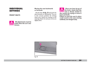 30
30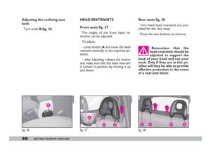 31
31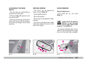 32
32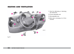 33
33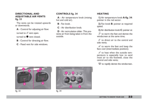 34
34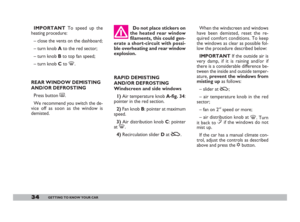 35
35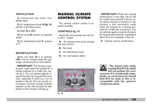 36
36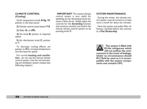 37
37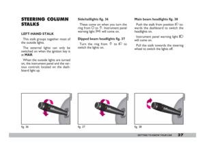 38
38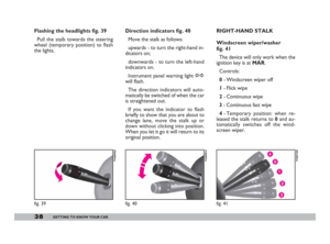 39
39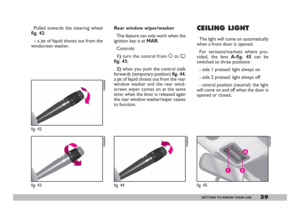 40
40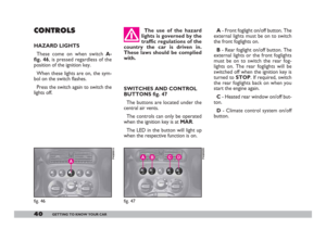 41
41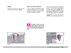 42
42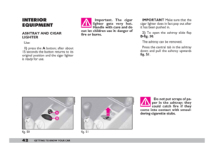 43
43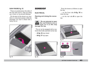 44
44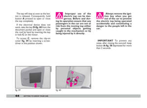 45
45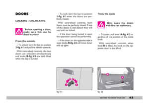 46
46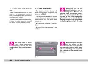 47
47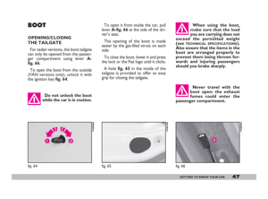 48
48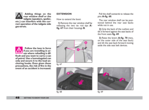 49
49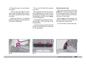 50
50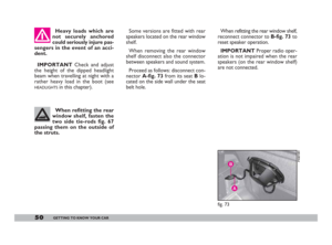 51
51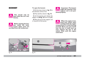 52
52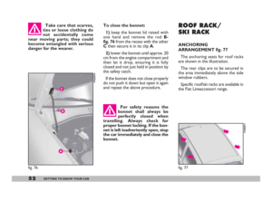 53
53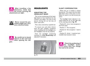 54
54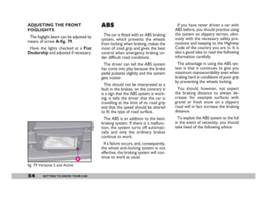 55
55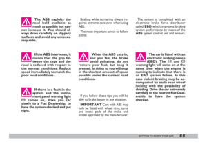 56
56 57
57 58
58 59
59 60
60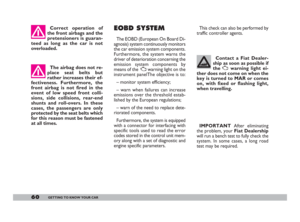 61
61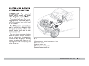 62
62 63
63 64
64 65
65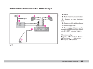 66
66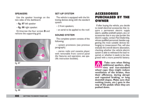 67
67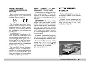 68
68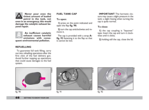 69
69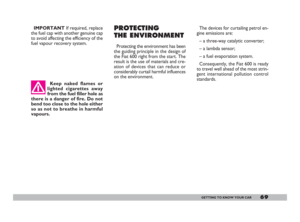 70
70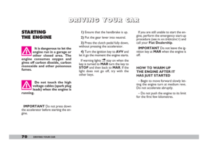 71
71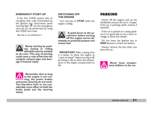 72
72 73
73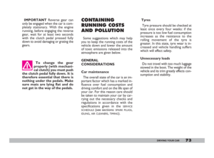 74
74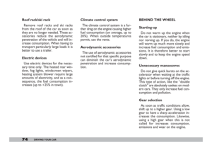 75
75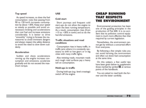 76
76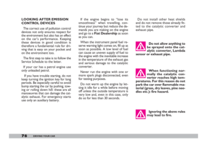 77
77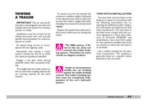 78
78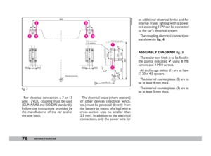 79
79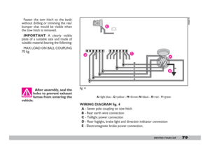 80
80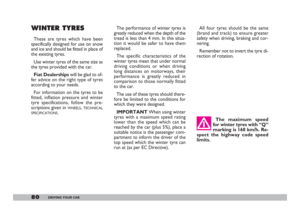 81
81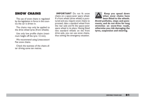 82
82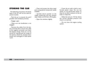 83
83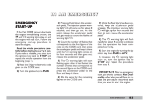 84
84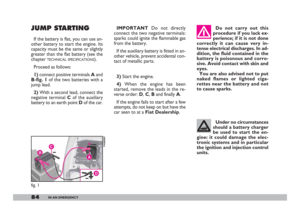 85
85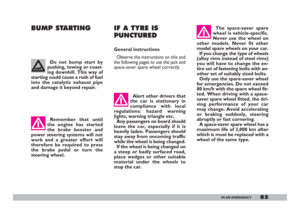 86
86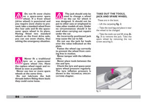 87
87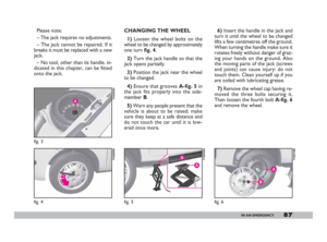 88
88 89
89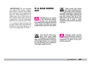 90
90 91
91 92
92 93
93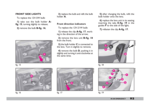 94
94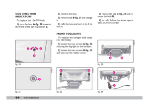 95
95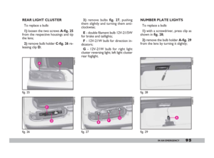 96
96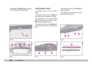 97
97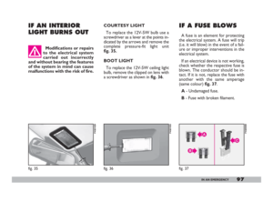 98
98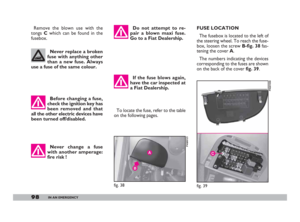 99
99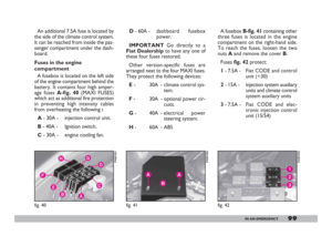 100
100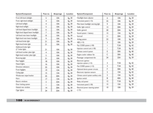 101
101 102
102 103
103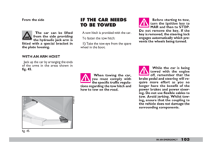 104
104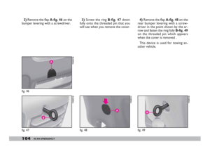 105
105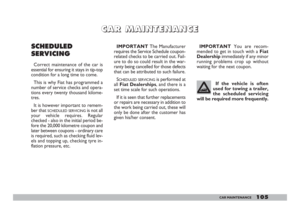 106
106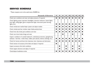 107
107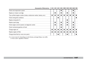 108
108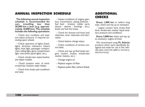 109
109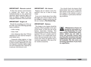 110
110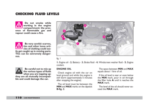 111
111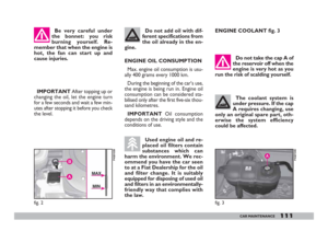 112
112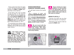 113
113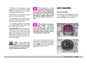 114
114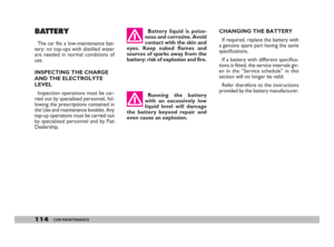 115
115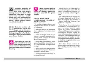 116
116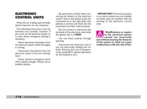 117
117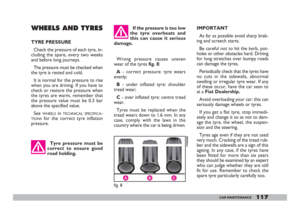 118
118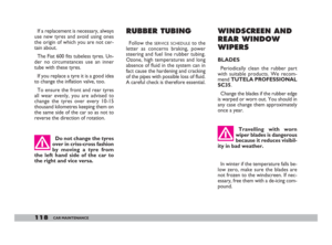 119
119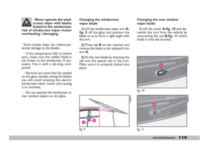 120
120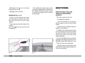 121
121 122
122 123
123 124
124 125
125 126
126 127
127 128
128 129
129 130
130 131
131 132
132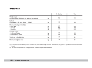 133
133 134
134 135
135 136
136 137
137 138
138 139
139 140
140 141
141 142
142 143
143 144
144 145
145 change bulb B-fig. 30 by pressing
a 12V-5W bulb into the holder. THIRD BRAKE LIGHT
To replace one or more 12V-5W
bulbs:
1) loosen the five screws A-fig. 31
and remove the complete")
