2006 YAMAHA TTR90 lock
[x] Cancel search: lockPage 18 of 390

ILLUSTRATED SYMBOLS
(Refer to the illustration)
Illustrated symbols 1 to 6 are designed as
thumb tabs to indicate the chapter’s number
and content.
1General information
2Specifications
3Regular inspection and adjustments
4Engine
5Chassis
6Electrical
Illustrated symbols 7 to D are used to identify
the specifications appearing in the text.
7With engine mounted
8Special tool
9Filling fluid
0Lubricant
ATightening
BSpecified value, Service limit
CEngine speed
DResistance (
Ω), Voltage (V), Electric current (A)
Illustrated symbols E to H in the exploded
diagram indicate grade of lubricant and loca-
tion of lubrication point.
EApply engine oil
FApply molybdenum disulfide oil
GApply lightweight lithium-soap base grease
HApply molybdenum disulfide grease
Illustrated symbols I to J in the exploded
diagrams indicate where to apply a locking
agent and when to install new parts.
IApply locking agent (LOCTITE®)
JUse new one 12
34
56
78
90
AB
CD
E
F
G
H
IJ
GEN
INFOSPEC
INSP
ADJ
ENG
CHAS–+ELEC
T R..
EM
LSM
LTNew
Page 32 of 390

1 - 4
GEN
INFO
IMPORTANT INFORMATION
EC132000
ALL REPLACEMENT PARTS
1. We recommend to use Yamaha genuine
parts for all replacements. Use oil and/or
grease recommended by Yamaha for
assembly and adjustment.
EC133000
GASKETS, OIL SEALS AND O-RINGS
1. All gaskets, oil seals, and O-rings should
be replaced when an engine is overhauled.
All gasket surfaces, oil seal lips, and O-
rings must be cleaned.
2. Properly oil all mating parts and bearings
during reassembly. Apply grease to the oil
seal lips.
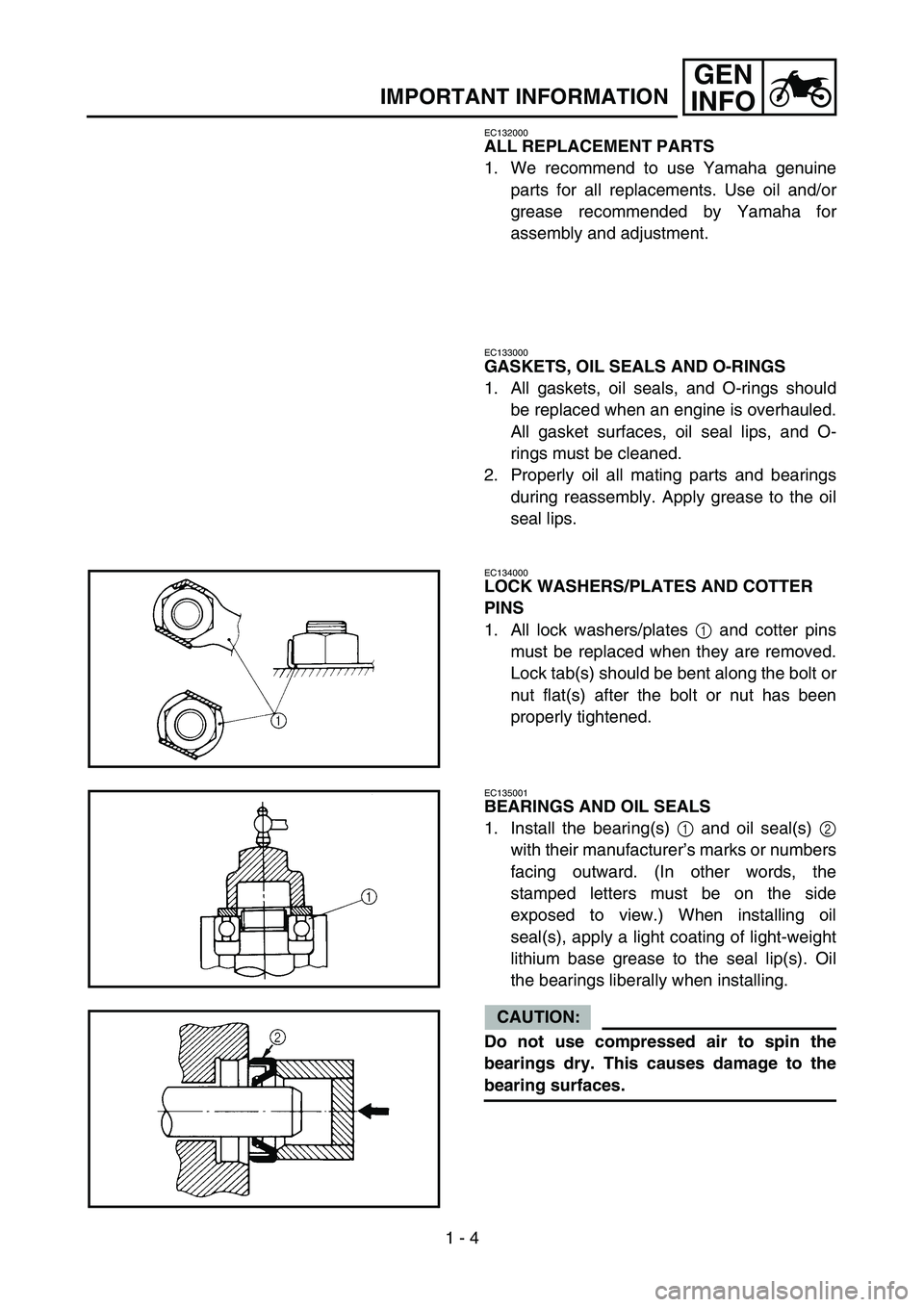
EC134000
LOCK WASHERS/PLATES AND COTTER
PINS
1. All lock washers/plates 1 and cotter pins
must be replaced when they are removed.
Lock tab(s) should be bent along the bolt or
nut flat(s) after the bolt or nut has been
properly tightened.
EC135001
BEARINGS AND OIL SEALS
1. Install the bearing(s) 1 and oil seal(s) 2
with their manufacturer’s marks or numbers
facing outward. (In other words, the
stamped letters must be on the side
exposed to view.) When installing oil
seal(s), apply a light coating of light-weight
lithium base grease to the seal lip(s). Oil
the bearings liberally when installing.
CAUTION:
Do not use compressed air to spin the
bearings dry. This causes damage to the
bearing surfaces.
Page 42 of 390

GEN
INFO
SPEZIALWERKZEUGE
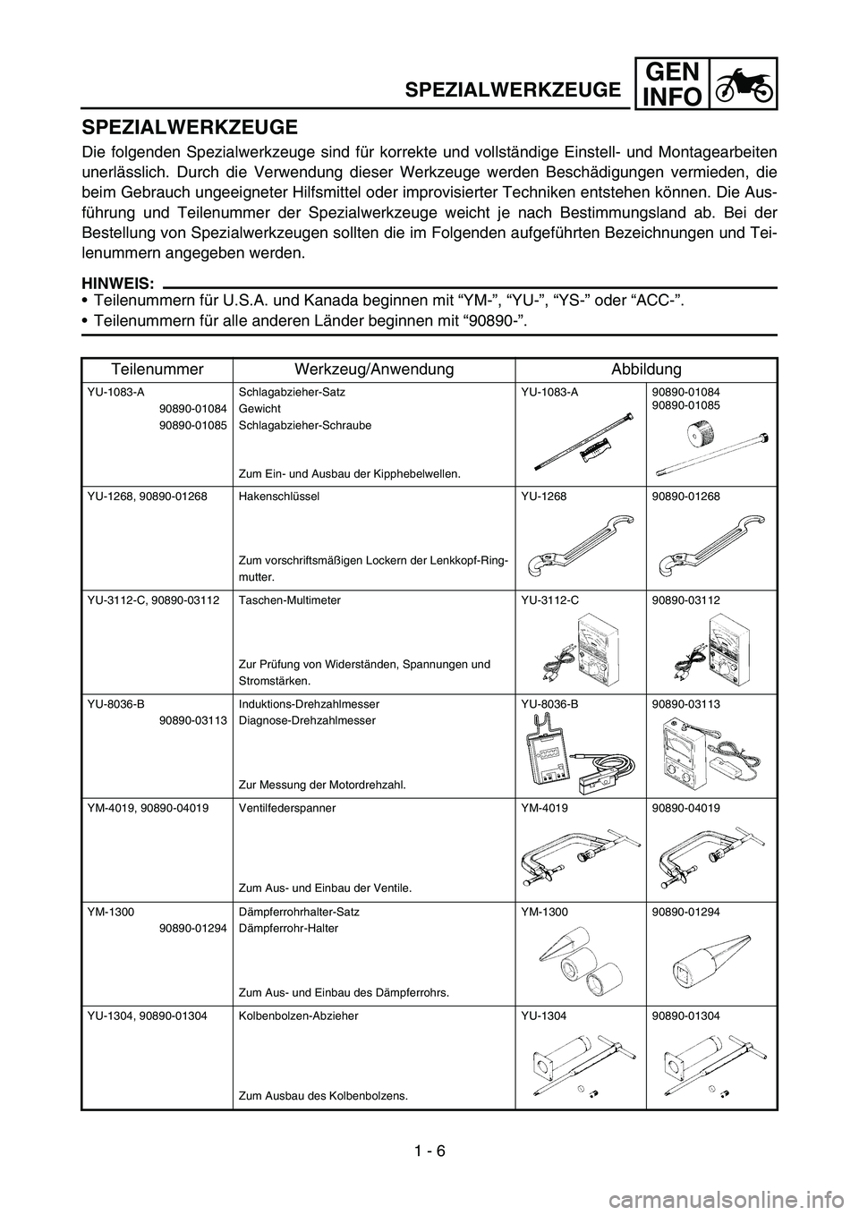
Die folgenden Spezialwerkzeuge sind für korrekte und vollständige Einstell- und Montagearbeiten
unerlässlich. Durch die Verwendung dieser Werkzeuge werden Beschädigungen vermieden, die
beim Gebrauch ungeeigneter Hilfsmittel oder improvisierter Techniken entstehen können. Die Aus-
führung und Teilenummer der Spezialwerkzeuge weicht je nach Bestimmungsland ab. Bei der
Bestellung von Spezialwerkzeugen sollten die im Folgenden aufgeführten Bezeichnungen und Tei-
lenummern angegeben werden.
HINWEIS:
Teilenummern für U.S.A. und Kanada beginnen mit “YM-”, “YU-”, “YS-” oder “ACC-”.
Teilenummern für alle anderen Länder beginnen mit “90890-”.
Teilenummer Werkzeug/Anwendung Abbildung
YU-1083-A
90890-01084
90890-01085Schlagabzieher-Satz
Gewicht
Schlagabzieher-Schraube
Zum Ein- und Ausbau der Kipphebelwellen.YU-1083-A 90890-01084
90890-01085
YU-1268, 90890-01268 Hakenschlüssel
Zum vorschriftsmäßigen Lockern der Lenkkopf-Ring-
mutter.YU-1268 90890-01268
YU-3112-C, 90890-03112 Taschen-Multimeter
Zur Prüfung von Widerständen, Spannungen und
Stromstärken.YU-3112-C 90890-03112
YU-8036-B
90890-03113Induktions-Drehzahlmesser
Diagnose-Drehzahlmesser
Zur Messung der Motordrehzahl.YU-8036-B 90890-03113
YM-4019, 90890-04019 Ventilfederspanner
Zum Aus- und Einbau der Ventile.YM-4019 90890-04019
YM-1300
90890-01294Dämpferrohrhalter-Satz
Dämpferrohr-Halter
Zum Aus- und Einbau des Dämpferrohrs.YM-1300 90890-01294
YU-1304, 90890-01304 Kolbenbolzen-Abzieher
Zum Ausbau des Kolbenbolzens.YU-1304 90890-01304
SPEZIALWERKZEUGE
1 - 6
Page 50 of 390

1 - 11
GEN
INFO
CONTROL FUNCTIONS
FUEL COCK
The fuel cock supplies fuel from the tank to
carburetor while filtering the fuel. The fuel cock
has the three positions:
OFF: With the lever in this position, fuel will not
flow. Always return the lever to this posi-
tion when the engine is not running.
ON: With the lever in this position, fuel flows
to the carburetor. Normal riding is done
with the lever in this position.
RES: This indicates reserve. If you run out of
fuel while riding, move the lever to this
position. FILL THE TANK AT THE FIRST
OPPORTUNITY. BE SURE TO SET
THE LEVER TO “ON” AFTER REFUEL-
ING.
STARTER LEVER (CHOKE)
When cold, the engine requires a richer air/fuel
mixture for starting. A separate starter circuit,
which is controlled by the starter lever 1, sup-
plies this mixture.
Pull the lever out to open the circuit (for start-
ing) and push the lever in to close the circuit.
FUEL TANK CAP
Remove the fuel tank cap 1 by turning
counter-clockwise.
WARNING
Do not overfill the fuel tank. Avoid spilling
fuel on the hot engine.
1
TOOL KIT
Spark plug wrench
Spark plug wrench 1 is used to remove and
install the spark plug.
Screw driver
This tool is used for preventive maintenance
and minor repairs.
1
Page 56 of 390

GEN
INFO
ANLASSEN UND
INBETRIEBNAHME
ACHTUNG:
Vor dem Start muss die “Routinekontrolle
vor Fahrtbeginn” ausgeführt werden.
WARNUNG
Den Motor niemals in einem geschlosse-
nen Raum anlassen oder betreiben. Motor-
abgase sind äußerst giftig und führen in
kurzer Zeit zu Bewusstlosigkeit und Tod.
Daher den Motor nur an einem gut belüfte-
ten Ort betreiben.
KALTEN MOTOR ANLASSEN
TT-R90
WARNUNG
Vor dem Anlassen sicherstellen, dass das
Getriebe in der Leerlaufstellung ist.
1. Den Kraftstoffhahn auf “ON” stellen.
2. Den Choke betätigen und den Gasdrehgriff
ganz schließen.
3. Den Motorstoppschalter “ENGINE STOP”
auf “” stellen.
4. Den Kickstarterhebel kräftig durchtreten,
um den Motor anzulassen.
5. Nach dem Anlassen den Motor einige Minu-
ten lang warm laufen lassen. Vor dem Anfah-
ren sicherstellen, dass der Chokehebel in die
Ausgangsstellung zurückgebracht wird.
TT-R90E
WARNUNG
Vor dem Anlassen sicherstellen, dass das
Getriebe in der Leerlaufstellung ist.
HINWEIS:
Das Motorrad ist mit einem Zündunterbre-
chungs- und Anlasssperrschalter-System
ausgerüstet. Der Motor kann nur dann mit
dem E-Starter angelassen werden, wenn
das Getriebe in der Leerlaufstellung ist.
Falls der Motor bei Verwendung des Elektro-
starters nicht sofort anspringt, den Starterschal-
ter freigeben und einige Sekunden bis zum
nächsten Startversuch warten. Um die Batterie
zu schonen, darf der Starterschalter jeweils nur
kurzzeitig betätigt werden. Den Motor niemals
länger als 10 Sekunden drehen. Falls der Motor
nicht mit dem Elektrostarter angelassen werden
kann, den Kickstarter benutzen.1. Den Kraftstoffhahn auf “ON” stellen.
2. Den Zündschlüssel auf “ON” stellen.
3. Das Getriebe in die Leerlaufstellung schalten.
4. Den Choke betätigen und den Gasdrehgriff
ganz schließen.
5. Den Motorstoppschalter “ENGINE STOP”
auf “” stellen.
6. Den Starterschalter drücken oder den Kick-
starterhebel durchtreten, um den Motor
anzulassen.
7. Nach dem Anlassen den Motor einige Minu-
ten lang warm laufen lassen. Vor dem Anfah-
ren sicherstellen, dass der Chokehebel in die
Ausgangsstellung zurückgebracht wird.
WARMEN MOTOR ANLASSEN
Den warmen Motor wie im Abschnitt “Kalten
Motor anlassen” beschrieben anlassen. Aller-
dings sollte der Choke nicht betätigt werden.
Den Gasdrehgriff leicht öffnen.
ACHTUNG:
Vor der ersten Inbetriebnahme unbedingt den
Abschnitt “Einfahrvorschriften” beachten.
MOTOR WARM FAHREN
Den Motor stets warm fahren, um ihm eine lange
Lebensdauer zu gewähren. Bei kaltem Motor
niemals stark beschleunigen! Der Motor ist aus-
reichend warmgefahren, wenn er bei abgeschal-
tetem Choke willig auf Gasgeben anspricht.
WARNUNG
Vor dem Losfahren sicherstellen, dass der
Seitenständer hochgeklappt bzw. abge-
nommen ist.
Ein ausgeklappter Seitenständer kann in
Kurven schwere Stürze verursachen.
EINFAHRVORSCHRIFTEN
Die Einfahrzeit ist wichtig, weil sie den vielen
Bauteilen des Motors erlaubt, sich einzupas-
sen. Außerdem kann der Fahrer sich während
dessen mit seiner Maschine vertraut machen.
Während der ersten fünf Betriebsstunden
unbedingt Vollgas vermeiden.
Nach der Probefahrt die Maschine auf lockere
Schraubverbindungen, Öllecks und andere
Probleme untersuchen.
Die Maschine gründlich kontrollieren und einstel-
len, insbesondere Seilzüge, Antriebskette und
Radspeichen.
ACHTUNG:
Am Ende der Einfahrzeit sicherstellen, dass
sämtliche Schraubverbindungen fest sind.
Bei Lockerheit nachziehen.
ANLASSEN UND INBETRIEBNAHME
1 - 13
Page 57 of 390

GEN
INFO
1 - 14
CLEANING AND STORAGE
EC1B0000
CLEANING AND STORAGE
EC1B1000
CLEANING
Frequent cleaning of your machine will
enhance its appearance, maintain good overall
performance, and extend the life of many com-
ponents.
1. Before washing the machine, block off the
end of the exhaust pipe to prevent water
from entering.
2. If the engine is excessively greasy, apply
some degreaser to it with a paint brush. Do
not apply degreaser to the chain, sprock-
ets, or wheel axles.
3. Rinse the dirt and degreaser off with a gar-
den hose; use only enough pressure to do
the job.
CAUTION:
Excessive hose pressure may cause water
seepage and contamination of wheel bear-
ings, front forks, brakes and transmission
seals. Many expensive repair bills have
resulted from improper high pressure
detergent applications such as those avail-
able in coin-operated car washers.
4. After the majority of the dirt has been
hosed off, wash all surfaces with warm
water and a mild detergent. Use an old
toothbrush to clean hard-to-reach places.
5. Rinse the machine off immediately with
clean water, and dry all surfaces with a soft
towel or cloth.
6. Immediately after washing, remove excess
water from the chain with a paper towel
and lubricate the chain to prevent rust.
7. Clean the seat with a vinyl upholstery
cleaner to keep the cover pliable and
glossy.
8. Automotive wax may be applied to all
painted or chromed surfaces. Avoid combi-
nation cleaner-waxes, as they may contain
abrasives.
9. After completing the above, start the
engine and allow it to idle for several min-
utes.
EC182001
STORAGE
If your machine is to be stored for 60 days or
more, some preventive measures must be
taken to avoid deterioration. After cleaning the
machine thoroughly, prepare it for storage as
follows:
1. Drain the fuel tank, fuel lines, and the car-
buretor float bowl.
2. Remove the spark plug, pour a tablespoon
of SAE 10W-30 motor oil in the spark plug
hole, and reinstall the plug. With the engine
stop switch pushed in, kick the engine over
several times to coat the cylinder walls with
oil.
3. Remove the drive chain, clean it thoroughly
with solvent, and lubricate it. Reinstall the
chain or store it in a plastic bag tied to the
frame.
4. Lubricate all control cables.
5. Block the frame up to raise the wheels off
the ground.
6. Tie a plastic bag over the exhaust pipe out-
let to prevent moisture from entering.
7. If the machine is to be stored in a humid or
salt-air environment, coat all exposed
metal surfaces with a film of light oil. Do not
apply oil to rubber parts or the seat cover.
NOTE:
Make any necessary repairs before the
machine is stored.
Page 65 of 390

SPEC
2 - 6 Stem runout limit ---- 0.02 mm
(0.0008 in)
Valve seat width IN 0.9 ~ 1.1 mm
(0.0354 ~ 0.0433 in)1.6 mm
(0.0630 in)
EX 0.9 ~ 1.1 mm
(0.0354 ~ 0.0433 in)1.6 mm
(0.0630 in)
Valve spring:
Free length IN 32.45 mm (1.28 in) 26.9 mm
(1.06 in)
EX 32.45 mm (1.28 in) 26.9 mm
(1.06 in)
Set length (valve closed) IN 24.2 mm (0.95 in) ----
EX 24.2 mm (0.95 in) ----
Compressed pressure (installed) IN 138 ~ 158 N
(14.07 ~ 16.11 kg,
31.02 ~ 35.52 lb)----
EX 138 ~ 158 N
(14.07 ~ 16.11 kg,
31.02 ~ 35.52 lb)----
Tilt limit IN ----
2.5°/1.4 mm
(2.5°/0.06 in)
EX ----2.5°/1.4 mm
(2.5°/0.06 in)
Direction of winding (top view) IN Clockwise ----
EX Clockwise ---- Item Standard Limit
*
MAINTENANCE SPECIFICATIONS
Page 69 of 390

SPEC
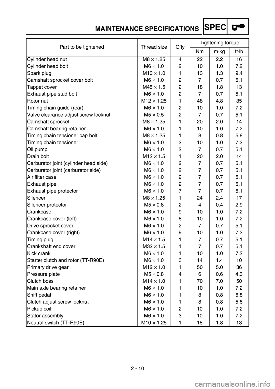
2 - 10 Part to be tightened Thread size Q’tyTightening torque
Nm m·kg ft·lb
Cylinder head nut M8 × 1.25 4 22 2.2 16
Cylinder head bolt M6 × 1.0 2 10 1.0 7.2
Spark plug M10 × 1.0 1 13 1.3 9.4
Camshaft sprocket cover bolt M6 × 1.0 2 7 0.7 5.1
Tappet cover M45 × 1.5 2 18 1.8 13
Exhaust pipe stud bolt M6 × 1.0 2 7 0.7 5.1
Rotor nut M12 × 1.25 1 48 4.8 35
Timing chain guide (rear) M6 × 1.0 2 10 1.0 7.2
Valve clearance adjust screw locknut M5 × 0.5 2 7 0.7 5.1
Camshaft sprocket M8 × 1.25 1 20 2.0 14
Camshaft bearing retainer M6 × 1.0 1 10 1.0 7.2
Timing chain tensioner cap bolt M8 × 1.25 1 8 0.8 5.8
Timing chain tensioner M6 × 1.0 2 10 1.0 7.2
Oil pump M6 × 1.0 2 7 0.7 5.1
Drain bolt M12 ×
1.5 1 20 2.0 14
Carburetor joint (cylinder head side) M6 ×
1.0 2 7 0.7 5.1
Carburetor joint (carburetor side) M6 ×
1.0 2 7 0.7 5.1
Air filter case M6 ×
1.0 2 7 0.7 5.1
Exhaust pipe M6 ×
1.0 2 7 0.7 5.1
Exhaust pipe protector M6 ×
1.0 7 7 0.7 5.1
Silencer M8 ×
1.25 1 24 2.4 17
Silencer protector M5 ×
0.8 2 4 0.4 2.9
Crankcase M6 × 1.0 9 10 1.0 7.2
Crankcase cover (left) M6 ×
1.0 8 10 1.0 7.2
Drive sprocket cover M6 × 1.0 2 7 0.7 5.1
Crankcase cover (right) M6 × 1.0 9 10 1.0 7.2
Timing plug M14 ×
1.5 1 7 0.7 5.1
Crankshaft end cover M32 ×
1.5 1 7 0.7 5.1
Kick crank M6 ×
1.0 1 10 1.0 7.2
Starter clutch and rotor (TT-R90E) M6 ×
1.0 3 14 1.4 10
Primary drive gear M12 ×
1.0 1 50 5.0 36
Pressure plate M5 ×
0.8 4 6 0.6 4.3
Clutch boss M14 ×
1.0 1 70 7.0 50
Main axle bearing retainer M6 × 1.0 1 10 1.0 7.2
Shift pedal M6 × 1.0 1 8 0.8 5.8
Clutch adjust screw locknut M6 × 1.0 1 8 0.8 5.8
Pickup coil M6 × 1.0 2 10 1.0 7.2
Stator assembly M6 × 1.0 3 10 1.0 7.2
Neutral switch (TT-R90E) M10 × 1.25 1 18 1.8 13
MAINTENANCE SPECIFICATIONS