2006 TOYOTA RAV4 ac-172
[x] Cancel search: ac-172Page 196 of 2000

2GR-FE ENGINE MECHANICAL – ENGINE ASSEMBLYEM–21
EM
REMOVAL
1. DISCHARGE REFRIGERANT FROM
REFRIGERATION SYSTEM (See page AC-172)
2. DISCHARGE FUEL SYSTEM PRESSURE (See page
FU-13)
3. DISCONNECT CABLE FROM NEGATIVE BATTERY
TERMINAL
CAUTION:
Wait at least 90 seconds after disconnecting the
cable from the negative (-) battery terminal to
prevent airbag and seat belt pretensioner activation.
4. REMOVE NO. 1 ENGINE UNDER COVER
(a) Remove the 4 bolts, 12 clips and under cover.
5. REMOVE REAR ENGINE UNDER COVER RH
(a) Remove the 2 clips and under cover.
6. REMOVE REAR ENGINE UNDER COVER LH
(a) Remove the 2 clips and under cover.
7. REMOVE NO. 2 ENGINE UNDER COVER
(a) Remove the 2 clips and under cover.
8. REMOVE FRONT FLOOR COVER (See page FU-34)
9. DRAIN ENGINE COOLANT (See page CO-8)
10. DRAIN ENGINE OIL (See page LU-4)
11. DRAIN AUTOMATIC TRANSAXLE FLUID
(a) 2WD:
Drain automatic transaxle fluid (see page AX-172).
(b) 4WD:
Drain automatic transaxle fluid (see page AX-173)
12. DRAIN TRANSFER OIL (for 4WD)
13. REMOVE HOOD SUB-ASSEMBLY (See page ED-4)
14. REMOVE V-BANK COVER SUB-ASSEMBLY
(a) Detach the 3 clips and remove the V-bank cover.
A137900
Page 687 of 2000
2GR-FE ENGINE MECHANICAL – ENGINE ASSEMBLYEM–41
EM
62. ADD AUTOMATIC TRANSAXLE FLUID
(a) 2WD:
Add automatic transmission fluid (see page AX-
177).
(b) 4WD:
Add automatic transmission fluid (see page AX-
178).
63. ADD TRANSFER OIL (for 4WD) (See page TF-45)
64. ADD ENGINE OIL (See page LU-6)
65. ADD ENGINE COOLANT (See page CO-8)
66. CHARGE REFRIGERANT (See page AC-172)
67. CHECK FOR LEAKAGE OF REFRIGERANT (See
page AC-173)
68. CHECK FOR ENGINE OIL LEAKS (See page LU-6)
69. CHECK FOR ENGINE COOLANT LEAKS (See page
CO-1)
70. CHECK FOR FUEL LEAKS
71. INSPECT EXHAUST GAS LEAKS
72. INSPECT SHIFT LEVER POSITION
(a) 2WD:
Inspect the shift lever position (see page AX-159).
(b) 4WD:
Inspect the shift lever position (see page AX-158).
73. ADJUST TRANSMISSION CONTROL CABLE
(a) 2WD:
Adjust the shift lever position (see page AX-159).
(b) 4WD:
Adjust the shift lever position (see page AX-159).
74. INSTALL FRONT FLOOR COVER (See page FU-39)
75. INSTALL NO. 2 ENGINE UNDER COVER
(a) Install the under cover with the 2 clips.
76. INSTALL REAR ENGINE UNDER COVER LH
(a) Install the under cover with the 2 clips.
77. INSTALL REAR ENGINE UNDER COVER RH
(a) Install the under cover with the 2 clips.
78. INSTALL NO. 1 ENGINE UNDER COVER
(a) Install the under cover with the 4 bolts and 12 clips.
Page 1663 of 2000
AC–218AIR CONDITIONING – COMPRESSOR AND PULLEY (for 2AZ-FE)
AC
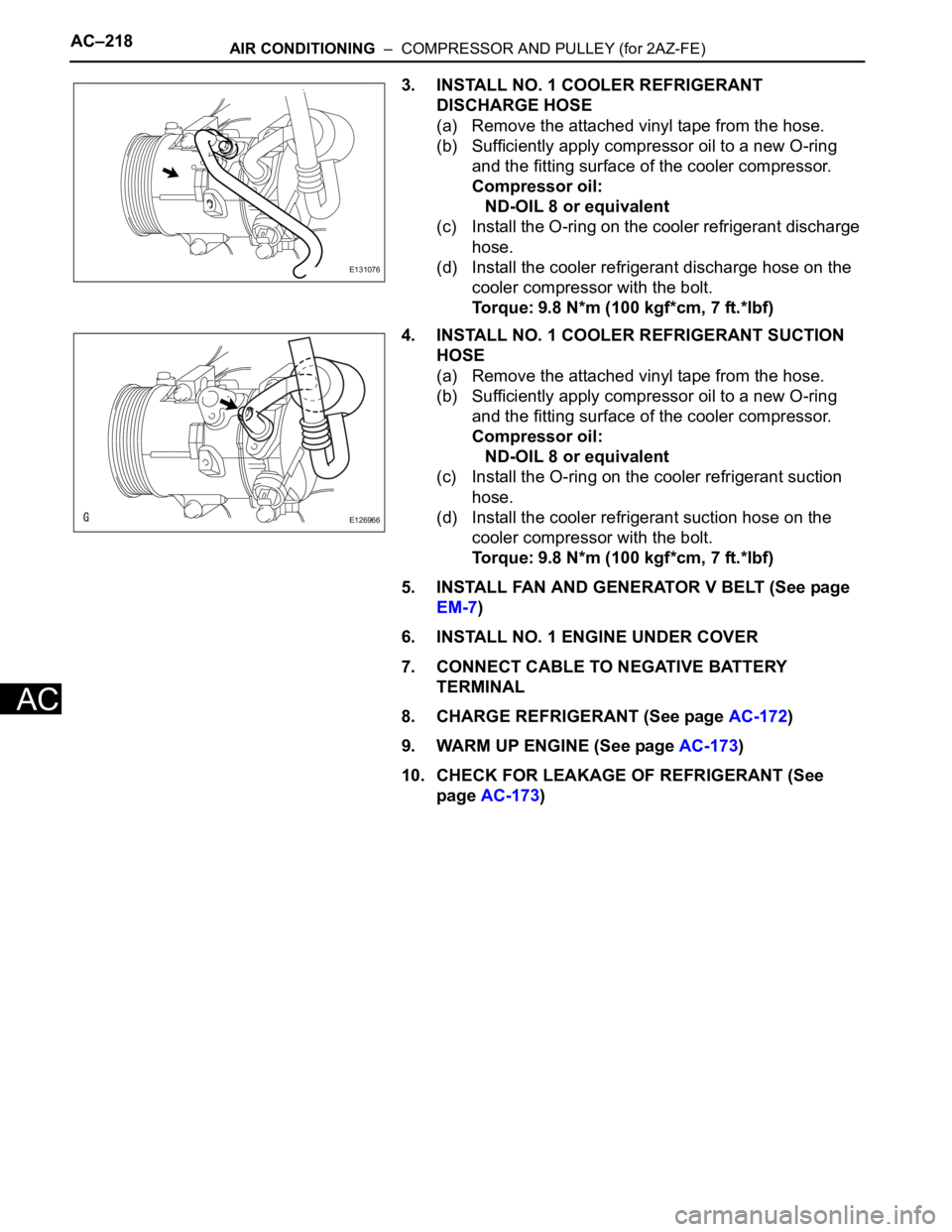
3. INSTALL NO. 1 COOLER REFRIGERANT
DISCHARGE HOSE
(a) Remove the attached vinyl tape from the hose.
(b) Sufficiently apply compressor oil to a new O-ring
and the fitting surface of the cooler compressor.
Compressor oil:
ND-OIL 8 or equivalent
(c) Install the O-ring on the cooler refrigerant discharge
hose.
(d) Install the cooler refrigerant discharge hose on the
cooler compressor with the bolt.
Torque: 9.8 N*m (100 kgf*cm, 7 ft.*lbf)
4. INSTALL NO. 1 COOLER REFRIGERANT SUCTION
HOSE
(a) Remove the attached vinyl tape from the hose.
(b) Sufficiently apply compressor oil to a new O-ring
and the fitting surface of the cooler compressor.
Compressor oil:
ND-OIL 8 or equivalent
(c) Install the O-ring on the cooler refrigerant suction
hose.
(d) Install the cooler refrigerant suction hose on the
cooler compressor with the bolt.
Torque: 9.8 N*m (100 kgf*cm, 7 ft.*lbf)
5. INSTALL FAN AND GENERATOR V BELT (See page
EM-7)
6. INSTALL NO. 1 ENGINE UNDER COVER
7. CONNECT CABLE TO NEGATIVE BATTERY
TERMINAL
8. CHARGE REFRIGERANT (See page AC-172)
9. WARM UP ENGINE (See page AC-173)
10. CHECK FOR LEAKAGE OF REFRIGERANT (See
page AC-173)
E131076
E126966
Page 1664 of 2000
AIR CONDITIONING – COMPRESSOR AND PULLEY (for 2GR-FE)AC–221
AC
INSTALLATION
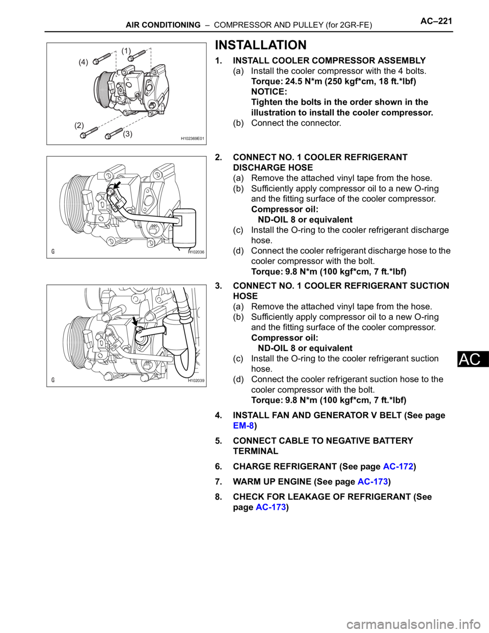
1. INSTALL COOLER COMPRESSOR ASSEMBLY
(a) Install the cooler compressor with the 4 bolts.
Torque: 24.5 N*m (250 kgf*cm, 18 ft.*lbf)
NOTICE:
Tighten the bolts in the order shown in the
illustration to install the cooler compressor.
(b) Connect the connector.
2. CONNECT NO. 1 COOLER REFRIGERANT
DISCHARGE HOSE
(a) Remove the attached vinyl tape from the hose.
(b) Sufficiently apply compressor oil to a new O-ring
and the fitting surface of the cooler compressor.
Compressor oil:
ND-OIL 8 or equivalent
(c) Install the O-ring to the cooler refrigerant discharge
hose.
(d) Connect the cooler refrigerant discharge hose to the
cooler compressor with the bolt.
Torque: 9.8 N*m (100 kgf*cm, 7 ft.*lbf)
3. CONNECT NO. 1 COOLER REFRIGERANT SUCTION
HOSE
(a) Remove the attached vinyl tape from the hose.
(b) Sufficiently apply compressor oil to a new O-ring
and the fitting surface of the cooler compressor.
Compressor oil:
ND-OIL 8 or equivalent
(c) Install the O-ring to the cooler refrigerant suction
hose.
(d) Connect the cooler refrigerant suction hose to the
cooler compressor with the bolt.
Torque: 9.8 N*m (100 kgf*cm, 7 ft.*lbf)
4. INSTALL FAN AND GENERATOR V BELT (See page
EM-8)
5. CONNECT CABLE TO NEGATIVE BATTERY
TERMINAL
6. CHARGE REFRIGERANT (See page AC-172)
7. WARM UP ENGINE (See page AC-173)
8. CHECK FOR LEAKAGE OF REFRIGERANT (See
page AC-173)
H102369E01
H102036
H102039
Page 1666 of 2000
AIR CONDITIONING – CONDENSERAC–225
AC
REMOVAL
1. DISCHARGE REFRIGERANT FROM
REFRIGERATION SYSTEM (See page AC-172)
2. DISCONNECT CABLE FROM NEGATIVE BATTERY
TERMINAL
CAUTION:
Wait at least 90 seconds after disconnecting the
cable from the negative (-) battery terminal to
prevent airbag and seat belt pretensioner activation.
3. REMOVE FRONT BUMPER COVER
(a) Remove front bumper cover (see page ET-4).
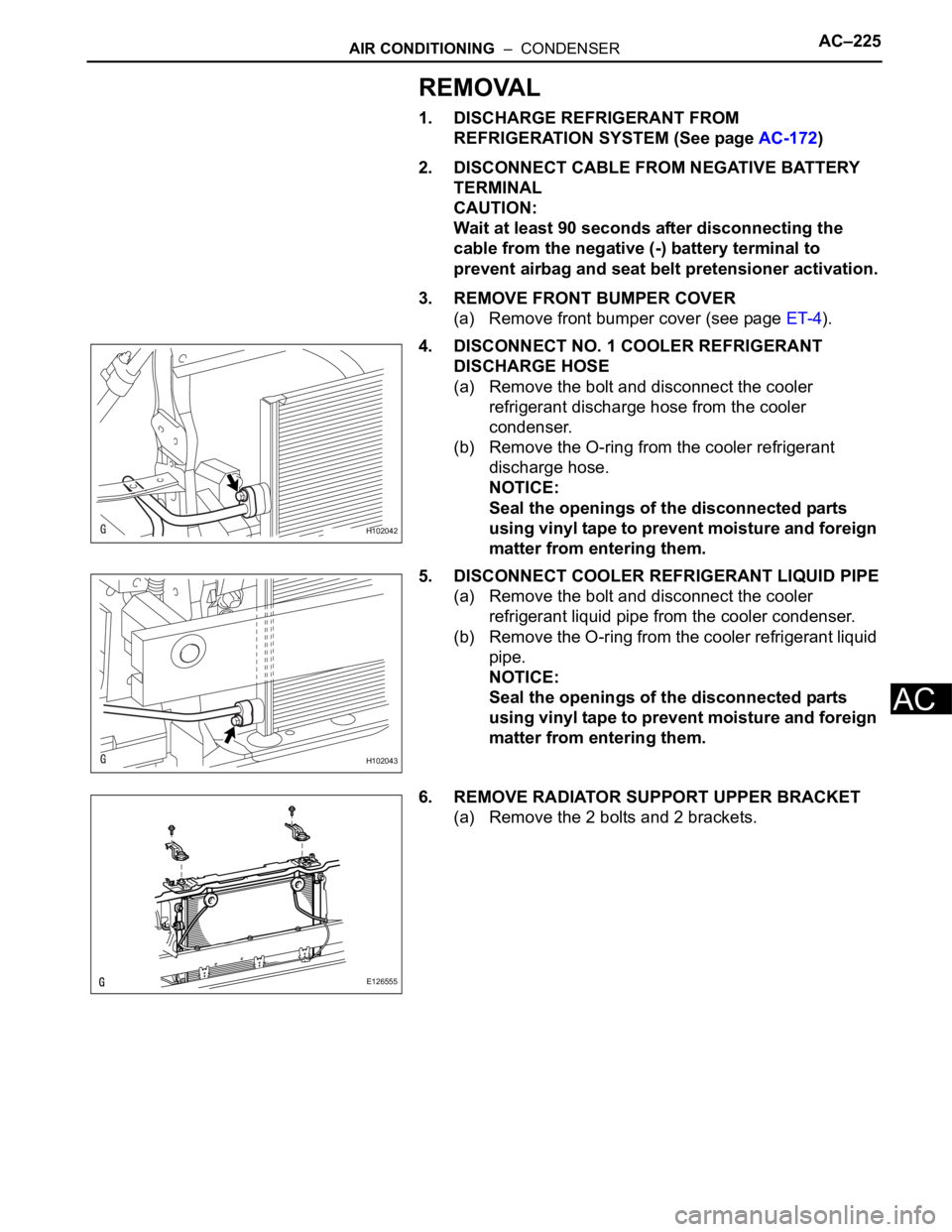
4. DISCONNECT NO. 1 COOLER REFRIGERANT
DISCHARGE HOSE
(a) Remove the bolt and disconnect the cooler
refrigerant discharge hose from the cooler
condenser.
(b) Remove the O-ring from the cooler refrigerant
discharge hose.
NOTICE:
Seal the openings of the disconnected parts
using vinyl tape to prevent moisture and foreign
matter from entering them.
5. DISCONNECT COOLER REFRIGERANT LIQUID PIPE
(a) Remove the bolt and disconnect the cooler
refrigerant liquid pipe from the cooler condenser.
(b) Remove the O-ring from the cooler refrigerant liquid
pipe.
NOTICE:
Seal the openings of the disconnected parts
using vinyl tape to prevent moisture and foreign
matter from entering them.
6. REMOVE RADIATOR SUPPORT UPPER BRACKET
(a) Remove the 2 bolts and 2 brackets.
H102042
H102043
E126555
Page 1669 of 2000
AC–228AIR CONDITIONING – CONDENSER
AC
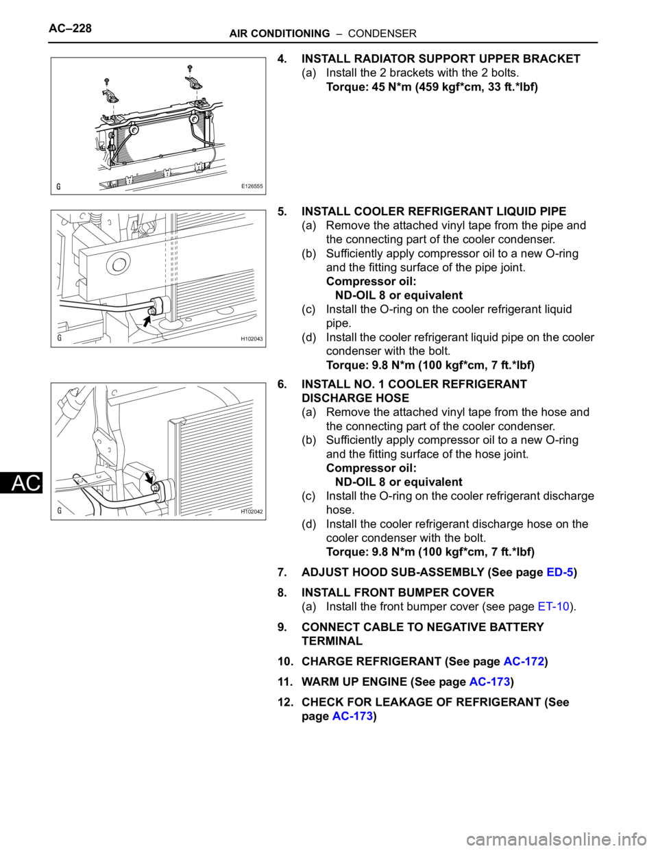
4. INSTALL RADIATOR SUPPORT UPPER BRACKET
(a) Install the 2 brackets with the 2 bolts.
Torque: 45 N*m (459 kgf*cm, 33 ft.*lbf)
5. INSTALL COOLER REFRIGERANT LIQUID PIPE
(a) Remove the attached vinyl tape from the pipe and
the connecting part of the cooler condenser.
(b) Sufficiently apply compressor oil to a new O-ring
and the fitting surface of the pipe joint.
Compressor oil:
ND-OIL 8 or equivalent
(c) Install the O-ring on the cooler refrigerant liquid
pipe.
(d) Install the cooler refrigerant liquid pipe on the cooler
condenser with the bolt.
Torque: 9.8 N*m (100 kgf*cm, 7 ft.*lbf)
6. INSTALL NO. 1 COOLER REFRIGERANT
DISCHARGE HOSE
(a) Remove the attached vinyl tape from the hose and
the connecting part of the cooler condenser.
(b) Sufficiently apply compressor oil to a new O-ring
and the fitting surface of the hose joint.
Compressor oil:
ND-OIL 8 or equivalent
(c) Install the O-ring on the cooler refrigerant discharge
hose.
(d) Install the cooler refrigerant discharge hose on the
cooler condenser with the bolt.
Torque: 9.8 N*m (100 kgf*cm, 7 ft.*lbf)
7. ADJUST HOOD SUB-ASSEMBLY (See page ED-5)
8. INSTALL FRONT BUMPER COVER
(a) Install the front bumper cover (see page ET-10).
9. CONNECT CABLE TO NEGATIVE BATTERY
TERMINAL
10. CHARGE REFRIGERANT (See page AC-172)
11. WARM UP ENGINE (See page AC-173)
12. CHECK FOR LEAKAGE OF REFRIGERANT (See
page AC-173)
E126555
H102043
H102042