Page 1334 of 2000

TF–6GF1A TRANSFER – ACTIVE TORQUE CONTROL 4WD SYSTEM
TF
SYSTEM DESCRIPTION
1. GENERAL DESCRIPTION
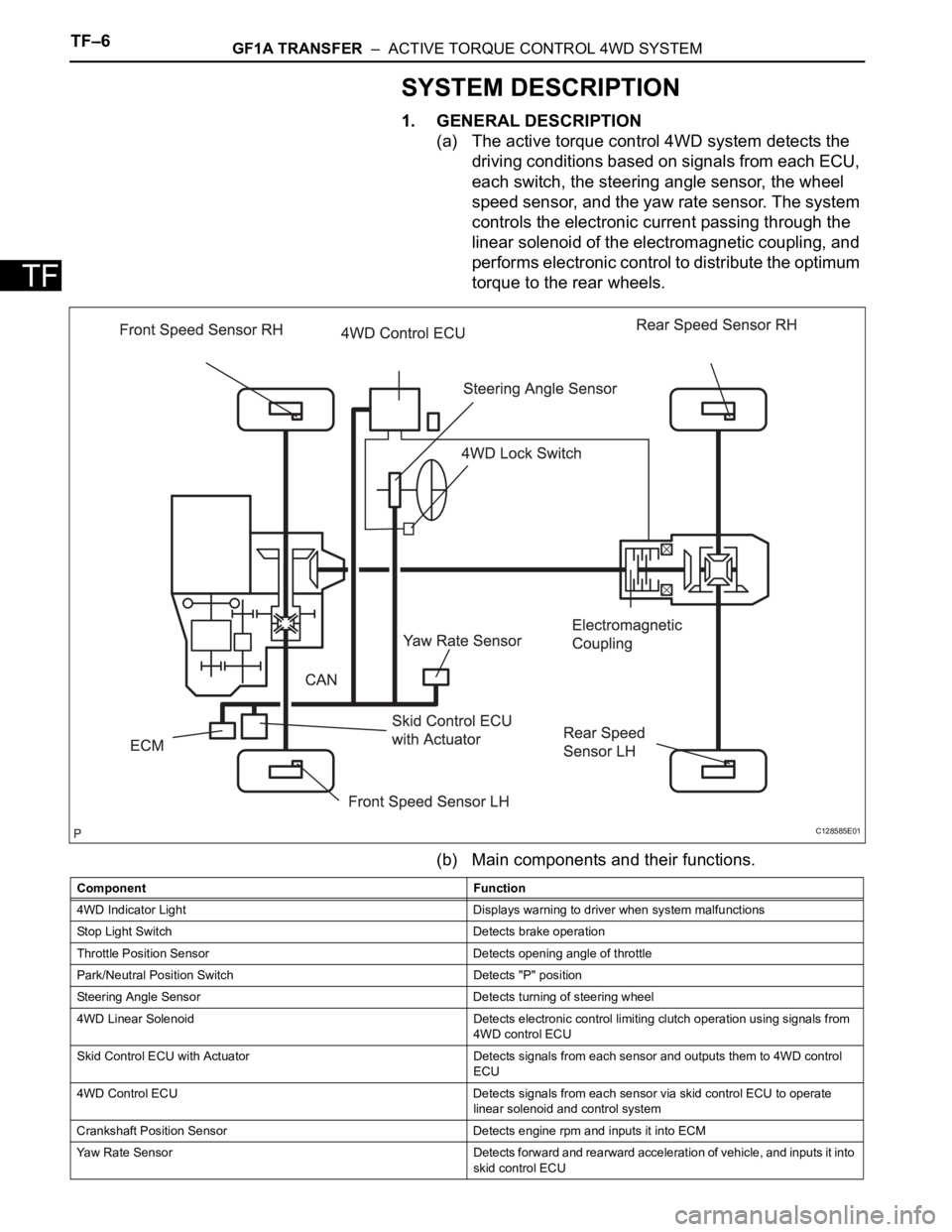
(a) The active torque control 4WD system detects the
driving conditions based on signals from each ECU,
each switch, the steering angle sensor, the wheel
speed sensor, and the yaw rate sensor. The system
controls the electronic current passing through the
linear solenoid of the electromagnetic coupling, and
performs electronic control to distribute the optimum
torque to the rear wheels.
(b) Main components and their functions.
C128585E01
Component Function
4WD Indicator Light Displays warning to driver when system malfunctions
Stop Light Switch Detects brake operation
Throttle Position Sensor Detects opening angle of throttle
Park/Neutral Position Switch Detects "P" position
Steering Angle Sensor Detects turning of steering wheel
4WD Linear Solenoid Detects electronic control limiting clutch operation using signals from
4WD control ECU
Skid Control ECU with Actuator Detects signals from each sensor and outputs them to 4WD control
ECU
4WD Control ECU Detects signals from each sensor via skid control ECU to operate
linear solenoid and control system
Crankshaft Position Sensor Detects engine rpm and inputs it into ECM
Yaw Rate Sensor Detects forward and rearward acceleration of vehicle, and inputs it into
skid control ECU
Page 1347 of 2000

GF1A TRANSFER – ACTIVE TORQUE CONTROL 4WD SYSTEMTF–19
TF
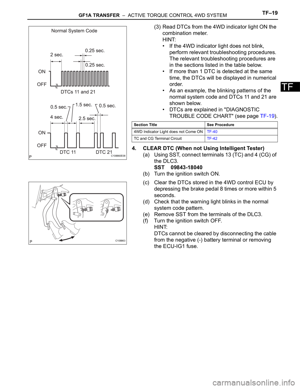
(3) Read DTCs from the 4WD indicator light ON the
combination meter.
HINT:
• If the 4WD indicator light does not blink,
perform relevant troubleshooting procedures.
The relevant troubleshooting procedures are
in the sections listed in the table below.
• If more than 1 DTC is detected at the same
time, the DTCs will be displayed in numerical
order.
• As an example, the blinking patterns of the
normal system code and DTCs 11 and 21 are
shown below.
• DTCs are explained in "DIAGNOSTIC
TROUBLE CODE CHART" (see page TF-19).
4. CLEAR DTC (When not Using Intelligent Tester)
(a) Using SST, connect terminals 13 (TC) and 4 (CG) of
the DLC3.
SST 09843-18040
(b) Turn the ignition switch ON.
(c) Clear the DTCs stored in the 4WD control ECU by
depressing the brake pedal 8 times or more within 5
seconds.
(d) Check that the warning light blinks in the normal
system code pattern.
(e) Remove SST from the terminals of the DLC3.
(f) Turn the ignition switch OFF.
HINT:
DTCs cannot be cleared by disconnecting the cable
from the negative (-) battery terminal or removing
the ECU-IG1 fuse.
C108860E08
Section Title See Procedure
4WD Indicator Light does not Come ONTF-40
TC and CG Terminal CircuitTF-42
C108863
Page 1348 of 2000
TF–20GF1A TRANSFER – ACTIVE TORQUE CONTROL 4WD SYSTEM
TF
FAIL-SAFE CHART
1. FAIL-SAFE FUNCTION
• If following malfunctions occur, the 4WD control ECU
will stop the function of 4WD control system or partly
change the function to control the system.
• If a malfunction occurs in the sensor signal or
actuator, the flow of electricity to the linear solenoid of
the electrical coupling is prohibited. As a result, the
system enters front wheel drive condition.
• When a component of the system malfunctions and
the fail-safe function activates, the component
operation is prohibited. However, if the system is
controlling the component and the fail-safe function
activates, the system operation is gradually stopped
to prevent sudden changes in the vehicle condition.
• When system control is not possible, the warning light
is illuminated to stop operation of the system
operation.
Page 1478 of 2000

TW–6TIRE AND WHEEL – TIRE PRESSURE WARNING SYSTEM
TW
SYSTEM DESCRIPTION
1. DESCRIPTION OF SYSTEM
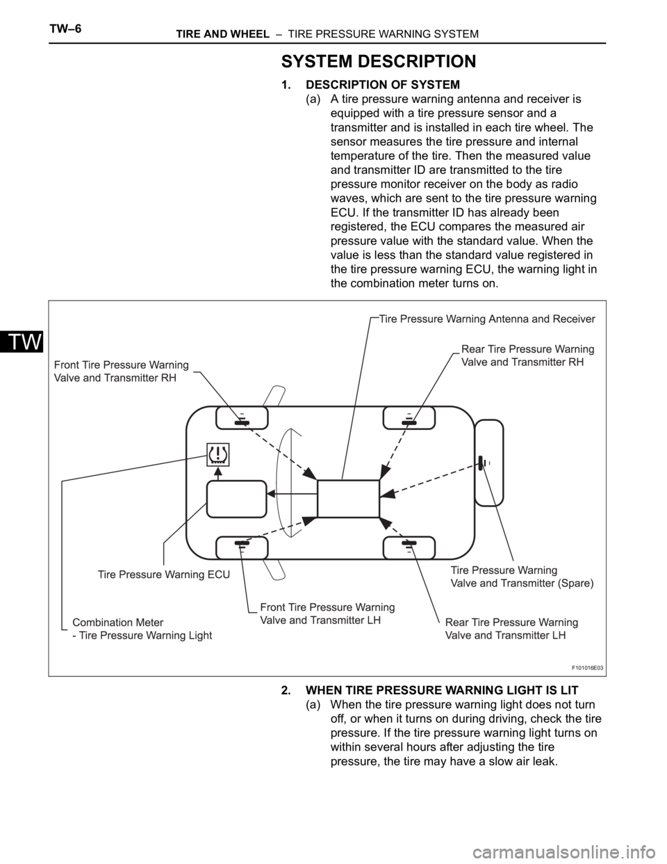
(a) A tire pressure warning antenna and receiver is
equipped with a tire pressure sensor and a
transmitter and is installed in each tire wheel. The
sensor measures the tire pressure and internal
temperature of the tire. Then the measured value
and transmitter ID are transmitted to the tire
pressure monitor receiver on the body as radio
waves, which are sent to the tire pressure warning
ECU. If the transmitter ID has already been
registered, the ECU compares the measured air
pressure value with the standard value. When the
value is less than the standard value registered in
the tire pressure warning ECU, the warning light in
the combination meter turns on.
2. WHEN TIRE PRESSURE WARNING LIGHT IS LIT
(a) When the tire pressure warning light does not turn
off, or when it turns on during driving, check the tire
pressure. If the tire pressure warning light turns on
within several hours after adjusting the tire
pressure, the tire may have a slow air leak.
F101016E03
Page 1479 of 2000

TIRE AND WHEEL – TIRE PRESSURE WARNING SYSTEMTW–7
TW
(b) Under the following conditions, the system may not
function properly;
• Areas, facilities or devices that use similar radio
frequencies are located in the vicinity of the
vehicle.
• Devices using similar radio frequencies are used
in the vehicle.
• Large amounts of snow or ice are stuck to the
vehicle, especially on the wheels and around the
wheel houses.
• The battery of the transmitter is depleted.
• Tires and wheels without tire pressure warning
valves and transmitters are used.
• Snow tires and tire chains are used.
• If wheels other than the specified ones are used,
the system may not function properly because
different radio waves are transmitted from the tire
pressure warning valve and transmitter.
• Depending on the tire type, the tire pressure
warning valve and transmitter may not function
properly even though the specified wheels are
used.
• The system may not function properly if it is
initialized with tire pressures which are not the
specified values.
(c) The average life of the grommet of the tire pressure
warning antenna and receiver is approximately 5
years, at which time it must be replaced. Retighten
the valve nut if the valve is leaking air, if it is less
than 5 years old, and there is no problem with the
grommets.
(d) After removing and installing the ECU or a sensor,
output a diagnosis code and check that it is a
normal code.
3. FUNCTION OF COMPONENTS
Components Function
Tire pressure warning antenna and receiver • Combined as a single unit with a disc wheel air valve, it measures
tire pressure and temperature, and transmits an ID number for
measurement value and identification
• Battery is built into valve
Tire pressure warning antenna and receiver Receives necessary signals from tire pressure warning antenna and
receiver and transmits them to tire pressure warning ECU
Tire pressure warning ECU • Receives signal from receiver and identifies it as vehicle's own
signal.
• If measurement value is equal to or lower than specified value, it
transmits a signal so that the air pressure warning light on
combination meter turns on.
Tire pressure warning light Located in the combination meter, it informs driver of lowered tire air
pressure and system failure
Page 1480 of 2000
TW–8TIRE AND WHEEL – TIRE PRESSURE WARNING SYSTEM
TW
HOW TO PROCEED WITH
TROUBLESHOOTING
HINT:
• Use these procedures to troubleshoot the tire pressure
warning system.
• *: Use the intelligent tester.
NEXT
Standard voltage:
11 to 14 V
If the voltage is below 11 V, recharge or replace the battery
before proceeding.
NEXT
(a) Check the indicator light (see page TW-17).
NEXT
(a) Check for DTC (see page TW-20).
(b) Clear the DTC (see page TW-20).
(c) Recheck for DTC (see page TW-20).
Result
B
A
(a) Check for tire pressure warning system DTC output (see
page TW-22).
NEXT
1VEHICLE BROUGHT TO WORKSHOP
2INSPECT BATTERY VOLTAGE
3CHECK INDICATOR LIGHT
4CHECK DTC*
Result Proceed to
DTC reoccurs A
DTC does not reoccur B
Go to step 6
5DTC CHART
Page 1481 of 2000
TIRE AND WHEEL – TIRE PRESSURE WARNING SYSTEMTW–9
TW
NEXT
Result
B
A
(a) Terminals of ECU (see page TW-16).
(b) DATA LIST/ACTIVE TEST (see page TW-21).
NEXT
NEXT
NEXT
6PROBLEM SYMPTOM CONFIRMATION
7PROBLEM SYMPTOMS TABLE
Result Proceed to
Fault is not listed in problem symptoms
tableA
Fault is listed in problem symptoms
tableB
Go to step 9
8OVERALL ANALYSIS AND TROUBLESHOOTING*
9REPAIR OR REPLACE
10CONFIRMATION TEST
END
Page 1482 of 2000

TW–10TIRE AND WHEEL – TIRE PRESSURE WARNING SYSTEM
TW
REGISTRATION
1. IN CASE OF TIRE PRESSURE WARNING ECU
REPLACEMENT
(a) Read ID stored in the old ECU using the intelligent
tester.
2. IN CASE OF TIRE PRESSURE WARNING VALVE AND
TRANSMITTER AND/OR TIRE PRESSURE WARNING
ECU REPLACEMENT
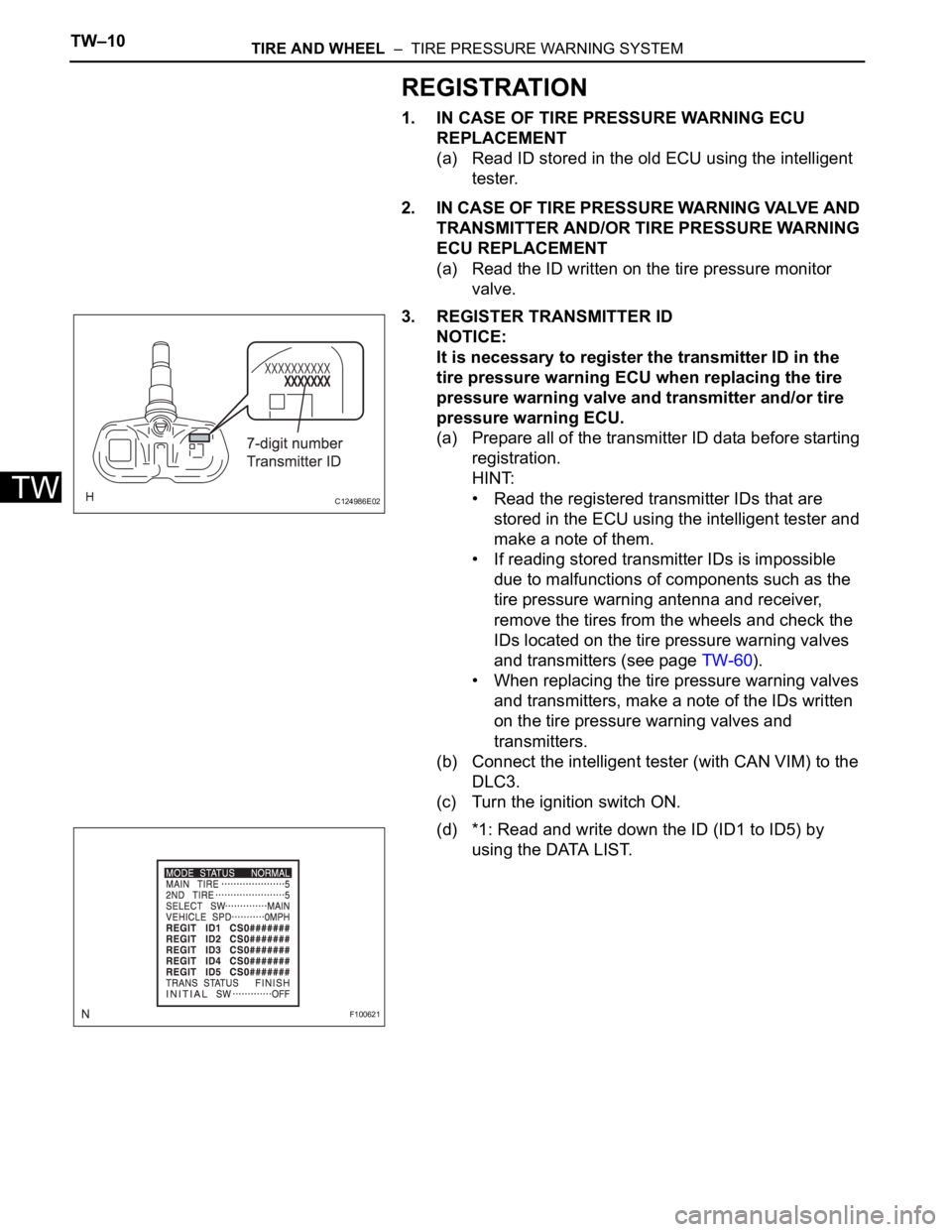
(a) Read the ID written on the tire pressure monitor
valve.
3. REGISTER TRANSMITTER ID
NOTICE:
It is necessary to register the transmitter ID in the
tire pressure warning ECU when replacing the tire
pressure warning valve and transmitter and/or tire
pressure warning ECU.
(a) Prepare all of the transmitter ID data before starting
registration.
HINT:
• Read the registered transmitter IDs that are
stored in the ECU using the intelligent tester and
make a note of them.
• If reading stored transmitter IDs is impossible
due to malfunctions of components such as the
tire pressure warning antenna and receiver,
remove the tires from the wheels and check the
IDs located on the tire pressure warning valves
and transmitters (see page TW-60).
• When replacing the tire pressure warning valves
and transmitters, make a note of the IDs written
on the tire pressure warning valves and
transmitters.
(b) Connect the intelligent tester (with CAN VIM) to the
DLC3.
(c) Turn the ignition switch ON.
(d) *1: Read and write down the ID (ID1 to ID5) by
using the DATA LIST.
C124986E02
F100621