Page 533 of 2000
IR–24INTERIOR – ROOF HEADLINING
IR
B129848E02
Page 534 of 2000
INTERIOR – ROOF HEADLININGIR–25
IR
B129849E02
Page 574 of 2000

SLIDING ROOF – SLIDING ROOF SYSTEMRF–3
RF
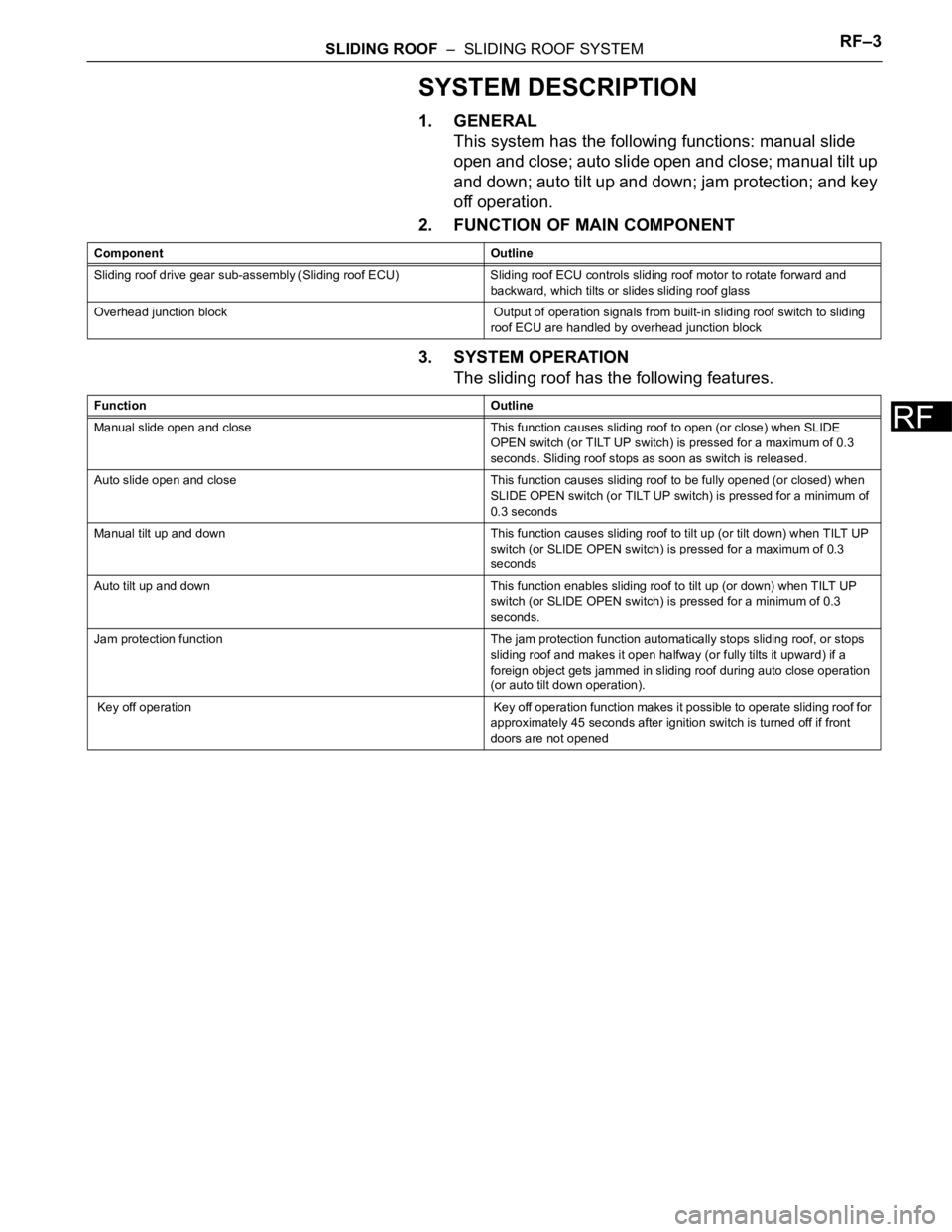
SYSTEM DESCRIPTION
1. GENERAL
This system has the following functions: manual slide
open and close; auto slide open and close; manual tilt up
and down; auto tilt up and down; jam protection; and key
off operation.
2. FUNCTION OF MAIN COMPONENT
3. SYSTEM OPERATION
The sliding roof has the following features.
Component Outline
Sliding roof drive gear sub-assembly (Sliding roof ECU) Sliding roof ECU controls sliding roof motor to rotate forward and
backward, which tilts or slides sliding roof glass
Overhead junction block Output of operation signals from built-in sliding roof switch to sliding
roof ECU are handled by overhead junction block
Function Outline
Manual slide open and close This function causes sliding roof to open (or close) when SLIDE
OPEN switch (or TILT UP switch) is pressed for a maximum of 0.3
seconds. Sliding roof stops as soon as switch is released.
Auto slide open and close This function causes sliding roof to be fully opened (or closed) when
SLIDE OPEN switch (or TILT UP switch) is pressed for a minimum of
0.3 seconds
Manual tilt up and down This function causes sliding roof to tilt up (or tilt down) when TILT UP
switch (or SLIDE OPEN switch) is pressed for a maximum of 0.3
seconds
Auto tilt up and down This function enables sliding roof to tilt up (or down) when TILT UP
switch (or SLIDE OPEN switch) is pressed for a minimum of 0.3
seconds.
Jam protection function The jam protection function automatically stops sliding roof, or stops
sliding roof and makes it open halfway (or fully tilts it upward) if a
foreign object gets jammed in sliding roof during auto close operation
(or auto tilt down operation).
Key off operation Key off operation function makes it possible to operate sliding roof for
approximately 45 seconds after ignition switch is turned off if front
doors are not opened
Page 575 of 2000
RF–4SLIDING ROOF – SLIDING ROOF SYSTEM
RF
HOW TO PROCEED WITH
TROUBLESHOOTING
HINT:
• Use these procedures to troubleshoot the sliding roof
system.
• *: Use the intelligent tester.
NEXT
Standard voltage:
11 to 14 V
If the voltage is below 11 V, recharge or replace the battery
before proceeding.
NEXT
(a) Using the intelligent tester, check if the Multiplex
Communication System (CAN) is functioning normally.
Result
B
A
Result
B
A
(a) Data List / Active Test (see page RF-7)
(b) Terminals of ECU (see page RF-5)
1VEHICLE BROUGHT TO WORKSHOP
2INSPECT BATTERY VOLTAGE
3INSPECT COMMUNICATION FUNCTION OF MULTIPLEX COMMUNICATION SYSTEM
(CAN)*
Result Proceed to
CAN DTC is not output A
CAN DTC is output B
Go to CAN COMMUNICATION SYSTEM
4PROBLEM SYMPTOMS TABLE
Result Proceed to
Fault is not listed in problem symptoms table A
Fault is listed in problem symptoms table B
Go to step 6
5OVERALL ANALYSIS AND TROUBLESHOOTING
Page 576 of 2000
SLIDING ROOF – SLIDING ROOF SYSTEMRF–5
RF
(c) On-vehicle Inspection (see page RF-9)
NEXT
NEXT
NEXT
6ADJUST, REPAIR OR REPLACE
7CONFIRMATION TEST
END
Page:
< prev 1-8 9-16 17-24