2006 TOYOTA RAV4 Crankshaft position sensor
[x] Cancel search: Crankshaft position sensorPage 134 of 2000

CHASSIS - 4WD SYSTEM
01MCH09Y
Electric Control Coupling
4WD ECU
Four-wheel Drive
Lock Switch
4WD LOCK
Indicator Light
4WD Warning
LightECM
Skid Control ECU
Main Body ECU
Ya w R a t e &
Deceleration Sensor
Steering Angle
SensorThrottle Position Sensor
Crankshaft Position Sensor
Park / Neutral Position
Switch
Speed Sensors
Stop Light Switch
Ambient Temperature
Sensor
Parking Brake Switch
CANH,
CANLCH-67
2. System Diagram
Page 136 of 2000

CHASSIS - 4WD SYSTEMCH-69
4. Function of Main Components
ComponentFunction
Combination
4WD LOCK
Indicator LightIlluminates to inform the driver of the 4WD LOCK mode control.Combination
Meter4WD
Warning LightIlluminates to warn the driver of a malfunction in the 4WD system.
Speed Sensor (4)Detects the wheel speed of each 4 wheel.
Steering Angle SensorDetects the direction and angle of the steering wheel.
Yaw Rate & Deceleration SensorDetects the vehicle’s longitudinal and lateral acceleration.
Crankshaft Position SensorDetects the engine speed and outputs it to the ECM.
Accelerator Pedal Position SensorDetects the accelerator pedal position and outputs it to the ECM.
Throttle Position SensorDetects the throttle valve position and outputs it to the ECM.
Park / Neutral Position SwitchDetects the neutral position of the transaxle and outputs it to the
ECM.
Stop Light SwitchDetects the brake pedal depressing signal.
Parking Brake SwitchDetects when the parking brake lever is pulled up.
Four-wheel Drive Lock SwitchSwitches between the AUTO and LOCK modes.
4WD ECU
Controls the amperage that is applied to the electromagnetic
solenoid of the electric control coupling based on the signals
provided by the sensors in order to optimally distribute drive torque
in accordance with driving conditions.
ECMOutputs signals such as the shift position signal, throttle position
signal, and crankshaft position signal to the 4WD ECU.
Skid Control ECUOutputs signals such as the vehicle speed signal and deceleration
signal to the 4WD ECU.
Electric Control CouplingDistributes drive torque in accordance with the amperage applied
by the 4WD ECU.
Page 220 of 2000

IN–48INTRODUCTION – TERMS
IN
GLOSSARY OF SAE AND TOYOTA
TERMS
This glossary lists all SAE-J1930 terms and abbreviations
used in this manual in compliance with SAE
recommendations, as well as their TOYOTA equivalents.
SAE
ABBREVIATIONSSAE TERMS TOYOTA TERMS ( )-ABBREVIATIONS
3GR Third Gear -
4GR Fourth Gear -
A/C Air Conditioning Air Conditioner
ACL Air Cleaner Air Cleaner, A/CL
AIR Secondary Air Injection Air Injection (AI)
AP Accelerator Pedal -
B+ Battery Positive Voltage +B, Battery Voltage
BARO Barometric Pressure HAC
CAC Charge Air Cooler Intercooler
CARB Carburetor Carburetor
CFI Continuous Fuel Injection -
CKP Crankshaft Position Crank Angle
CL Closed Loop Closed Loop
CMP Camshaft Position Cam Angle
CPP Clutch Pedal Position -
CTOX Continuous Trap Oxidizer -
CTP Closed Throttle Position LL ON, Idle ON
DFI Direct Fuel Injection Direct Injection (DI/INJ)
DI Distributor Ignition -
DLC3 Data Link Connector 3 OBD II Diagnostic Connector
DTC Diagnostic Trouble Code Diagnostic Trouble Code
DTM Diagnostic Test Mode -
ECL Engine Coolant Level -
ECM Engine Control Module Engine Electronic Control Unit (ECU)
ECT Engine Coolant Temperature Coolant Temperature, Water Temperature (THW)
EEPROM Electrically Erasable Programmable Read Only MemoryElectrically Erasable Programmable Read Only Memory
(EEPROM)
EFE Early Fuel Evaporation Cold Mixture Heater (CMH), Heat Control Valve (HCV)
EGR Exhaust Gas Recirculation Exhaust Gas Recirculation (EGR)
EI Electronic Ignition Distributorless Ignition (DLI)
EM Engine Modification Engine Modification (EM)
EPROM Erasable Programmable Read Only Memory Programmable Read Only Memory (PROM)
EVAP Evaporative Emission Evaporative Emission Control (EVAP)
FC Fan Control -
FEEPROMFlash Electrically Erasable Programmable Read Only
Memory-
FEPROM Flash Erasable Programmable Read Only Memory -
FF Flexible Fuel -
FP Fuel Pump Fuel Pump
GEN Generator Alternator
GND Ground Ground (GND)
HO2S Heated Oxygen Sensor Heated Oxygen Sensor (HO2S)
IAC Idle Air Control Idle Speed Control (ISC)
Page 380 of 2000
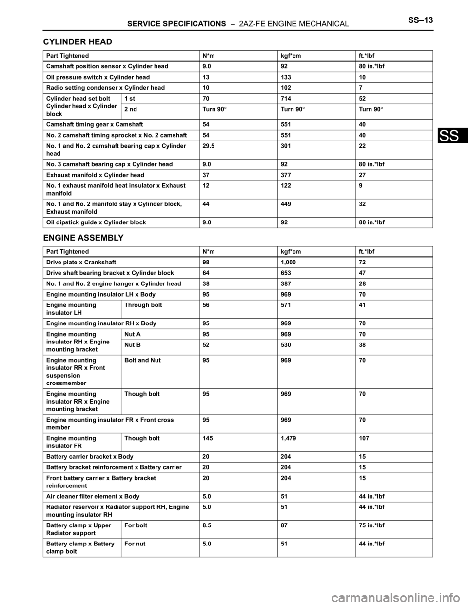
SERVICE SPECIFICATIONS – 2AZ-FE ENGINE MECHANICALSS–13
SS
CYLINDER HEAD
ENGINE ASSEMBLY
Part Tightened N*m kgf*cm ft.*lbf
Camshaft position sensor x Cylinder head 9.0 92 80 in.*lbf
Oil pressure switch x Cylinder head 13 133 10
Radio setting condenser x Cylinder head 10 102 7
Cylinder head set bolt
Cylinder head x Cylinder
block1 st 70 714 52
2 nd Turn 90
Tu r n 9 0Tu r n 9 0
Camshaft timing gear x Camshaft 54 551 40
No. 2 camshaft timing sprocket x No. 2 camshaft 54 551 40
No. 1 and No. 2 camshaft bearing cap x Cylinder
head29.5 301 22
No. 3 camshaft bearing cap x Cylinder head 9.0 92 80 in.*lbf
Exhaust manifold x Cylinder head 37 377 27
No. 1 exhaust manifold heat insulator x Exhaust
manifold12 122 9
No. 1 and No. 2 manifold stay x Cylinder block,
Exhaust manifold44 449 32
Oil dipstick guide x Cylinder block 9.0 92 80 in.*lbf
Part Tightened N*m kgf*cm ft.*lbf
Drive plate x Crankshaft 98 1,000 72
Drive shaft bearing bracket x Cylinder block 64 653 47
No. 1 and No. 2 engine hanger x Cylinder head 38 387 28
Engine mounting insulator LH x Body 95 969 70
Engine mounting
insulator LHThrough bolt 56 571 41
Engine mounting insulator RH x Body 95 969 70
Engine mounting
insulator RH x Engine
mounting bracketNut A 95 969 70
Nut B 52 530 38
Engine mounting
insulator RR x Front
suspension
crossmemberBolt and Nut 95 969 70
Engine mounting
insulator RR x Engine
mounting bracketThough bolt 95 969 70
Engine mounting insulator FR x Front cross
member95 969 70
Engine mounting
insulator FRThough bolt 145 1,479 107
Battery carrier bracket x Body 20 204 15
Battery bracket reinforcement x Battery carrier 20 204 15
Front battery carrier x Battery bracket
reinforcement20 204 15
Air cleaner filter element x Body 5.0 51 44 in.*lbf
Radiator reservoir x Radiator support RH, Engine
mounting insulator RH5.0 51 44 in.*lbf
Battery clamp x Upper
Radiator supportFor bolt 8.5 87 75 in.*lbf
Battery clamp x Battery
clamp boltFor nut 5.0 51 44 in.*lbf
Page 384 of 2000
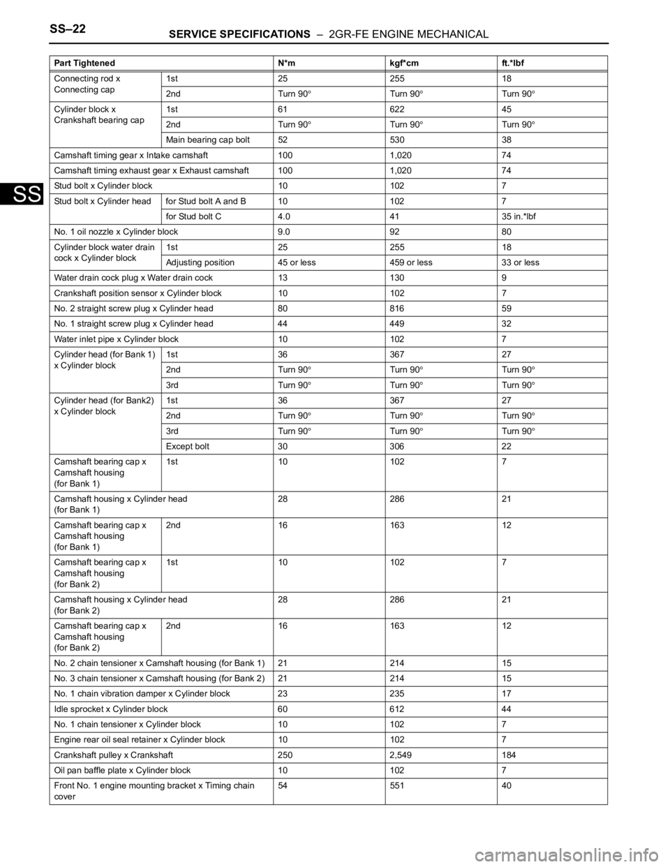
SS–22SERVICE SPECIFICATIONS – 2GR-FE ENGINE MECHANICAL
SS
Connecting rod x
Connecting cap1st 25 255 18
2nd Turn 90
Turn 90Turn 90
Cylinder block x
Crankshaft bearing cap1st 61 622 45
2nd Turn 90
Turn 90Turn 90
Main bearing cap bolt 52 530 38
Camshaft timing gear x Intake camshaft 100 1,020 74
Camshaft timing exhaust gear x Exhaust camshaft 100 1,020 74
Stud bolt x Cylinder block 10 102 7
Stud bolt x Cylinder head for Stud bolt A and B 10 102 7
for Stud bolt C 4.0 41 35 in.*lbf
No. 1 oil nozzle x Cylinder block 9.0 92 80
Cylinder block water drain
cock x Cylinder block1st 25 255 18
Adjusting position 45 or less 459 or less 33 or less
Water drain cock plug x Water drain cock 13 130 9
Crankshaft position sensor x Cylinder block 10 102 7
No. 2 straight screw plug x Cylinder head 80 816 59
No. 1 straight screw plug x Cylinder head 44 449 32
Water inlet pipe x Cylinder block 10 102 7
Cylinder head (for Bank 1)
x Cylinder block1st 36 367 27
2nd Turn 90
Turn 90Turn 90
3rd Turn 90Turn 90Turn 90
Cylinder head (for Bank2)
x Cylinder block1st 36 367 27
2nd Turn 90
Turn 90Turn 90
3rd Turn 90Turn 90Turn 90
Except bolt 30 306 22
Camshaft bearing cap x
Camshaft housing
(for Bank 1)1st 10 102 7
Camshaft housing x Cylinder head
(for Bank 1)28 286 21
Camshaft bearing cap x
Camshaft housing
(for Bank 1)2nd 16 163 12
Camshaft bearing cap x
Camshaft housing
(for Bank 2)1st 10 102 7
Camshaft housing x Cylinder head
(for Bank 2)28 286 21
Camshaft bearing cap x
Camshaft housing
(for Bank 2)2nd 16 163 12
No. 2 chain tensioner x Camshaft housing (for Bank 1) 21 214 15
No. 3 chain tensioner x Camshaft housing (for Bank 2) 21 214 15
No. 1 chain vibration damper x Cylinder block 23 235 17
Idle sprocket x Cylinder block 60 612 44
No. 1 chain tensioner x Cylinder block 10 102 7
Engine rear oil seal retainer x Cylinder block 10 102 7
Crankshaft pulley x Crankshaft 250 2,549 184
Oil pan baffle plate x Cylinder block 10 102 7
Front No. 1 engine mounting bracket x Timing chain
cover54 551 40 Part Tightened N*m kgf*cm ft.*lbf
Page 483 of 2000

2AZ-FE ENGINE CONTROL SYSTEM – SFI SYSTEMES–29
ES
PROBLEM SYMPTOMS TABLE
HINT:
Use the table below to help determine the cause of the
problem symptom. The potential causes of the symptoms are
listed in order of probability in the "Suspected area" column of
the table. Check each symptom by checking the suspected
areas in the order they are listed. Replace parts as
necessary.
SFI system
Symptom Suspected area See page
Engine does not crank (Does not start)1. BatteryCH-4
2. StarterST-8
3. Starter relayST-16
4. Park/neutral position switchAX-108
5. Immobiliser systemEI-3
No initial combustion (Does not start)1. ECM power source circuitES-366
2. Crankshaft position sensorES-402
3. Camshaft position sensorES-399
4. Ignition systemIG-4
5. Fuel pump control circuitES-378
6. ECMES-26
7. VC output circuitES-373
Engine cranks normally but difficult to start1. Fuel pump control circuitES-378
2. CompressionEM-3
Difficult to start with cold engine1. Ignition systemIG-4
2. Spark plugIG-7
3. Fuel pump control circuitES-378
4. InjectorFU-11
Difficult to start with warm engine1. InjectorFU-11
2. Ignition systemIG-4
3. Spark plugIG-7
4. Fuel pump control circuitES-378
High engine idle speed1. Electronic throttle control systemES-265
2. A/C signal circuit -
3. ECM power source circuitES-366
Low engine idle speed (Poor idling)1. Electronic throttle control systemES-265
2. A/C signal circuit -
3. Fuel pump control circuitES-378
4. Air induction systemEC-7
5. PCV hoseEC-7
Rough idling1. CompressionEM-3
2. Spark plugIG-7
3. InjectorFU-11
4. Ignition systemIG-4
5. Fuel pump control circuitES-378
6. Electronic throttle control systemES-265
7. Air induction systemEC-7
8. PCV hoseEC-7
9. Mass air flow meterES-391
Page 486 of 2000

ES–322AZ-FE ENGINE CONTROL SYSTEM – SFI SYSTEM
ES
VPA (A9-55) - EPA (A9-59) W - YAccelerator pedal position
sensor (for engine control)Ignition switch ON,
Accelerator pedal released0.5 to 1.1 V
Ignition switch ON,
Accelerator pedal fully depressed2.6 to 4.5 V
VPA2 (A9-56) - EPA2 (A9-60) R - OAccelerator pedal position
sensor (for sensor
malfunctioning detection)Ignition switch ON,
Accelerator pedal released1.2 to 2.0 V
Ignition switch ON,
Accelerator pedal fully depressed3.4 to 5.0 V
VCPA (A9-57) - EPA (A9-59) B - YPower source of
accelerator pedal position
sensor (for VPA)Ignition switch ON 4.5 to 5.5 V
VCP2 (A9-58) - EPA2 (A9-60) L - OPower source of
accelerator pedal position
sensor (for VPA2)Ignition switch ON 4.5 to 5.5 V
HA1A (B30-109) - E04 (B30-46) L - W-B A/F sensor heaterIdling Below 3.0 V
Ignition switch ON 9 to 14 V
A1A+ (B30-112) - E1 (B30-104) B -BR A/F sensor Ignition switch ON 3.3 V*
A1A- (B30-113) - E1 (B30-104) R - BR A/F sensor Ignition switch ON3.0 V*
HT1B (B30-47) - E03 (B30-86) R - W-BHeated oxygen sensor
heaterIdling Below 3.0 V
Ignition switch ON 9 to 14 V
OX1B (B30-64) - EX1B (B30-87) B - BR Heated oxygen sensorEngine speed maintained at 2,500
rpm for 2 minutes after warming up
sensorPulse generation (see
waveform 2)
#10 (B30-108) - E01 (B30-45)
#20 (B30-107) - E01 (B30-45)
#30 (B30-106) - E01 (B30-45)
#40 (B30-105) - E01 (B30-45)L - W-B
G - W-B
B - W-B
W - W-BInjectorIgnition switch ON 9 to 14 V
IdlingPulse generation (see
waveform 3)
KNK1 (B30-110) - EKNK (B30-
111 )B - W Knock sensorEngine speed maintained at 4,000
after warming up enginePulse generation (see
waveform 4)
G2+ (B30-99) - G2- (B30-98) L - Y Camshaft position sensor IdlingPulse generation (see
waveform 5)
NE+ (B30-122) - NE- (B30-121) W - B Crankshaft position sensor IdlingPulse generation (see
waveform 5)
IGT1 (B30-85) - E1 (B30-104)
IGT2 (B30-84) - E1 (B30-104)
IGT3 (B30-83) - E1 (B30-104)
IGT4 (B30-82) - E1 (B30-104)R - BR
P - BR
G - BR
L - BRIgnition coil (ignition
signal)IdlingPulse generation (see
waveform 6)
IGF1 (B30-81) - E1 (B30-104) W - BRIgnition coil (ignition
confirmation signal)Ignition switch ON 4.5 to 5.5 V
IdlingPulse generation (see
waveform 6)
PRG (B30-49) - E1 (B30-104) G - BR Purge VSVIgnition switch ON 9 to 14 V
IdlingPulse generation (see
waveform 7)
SPD (A9-8) - E1 (B30-104) V - BRSpeed signal from
combination meterDriving at 20 km/h (12 mph)Pulse generation (see
waveform 8)
STA (A9-48) - E1 (B30-104) LG - BR Starter signal Cranking 5.5 V or
more
STAR (B30-52) - E1 (B30-104) W - BR Starter relay controlIgnition switch ON Below 1.5 V
Cranking 6.0 V or more
STP (A9-36) - E1 (B30-104) L - BR Stop light switchBrake pedal depressed 7.5 to 14 V
Brake pedal released Below 1.5 V
ST1- (A9-35) - E1 (B30-104) GR - BRStop light switch
(opposite to STP terminal)Ignition switch ON,
Brake pedal depressedBelow 1.5 V
Ignition switch ON,
Brake pedal released7.5 to 14 V
M+ (B30-42) - ME01 (B30-43) B - W-B Throttle actuator Idling with warm enginePulse generation (see
waveform 9) Symbols (Terminal No.) Wiring Colors Terminal Descriptions ConditionsSpecified
Conditions
Page 489 of 2000

2AZ-FE ENGINE CONTROL SYSTEM – SFI SYSTEMES–35
ES
5. WAVEFORM 5
Crankshaft position sensor and Camshaft position
sensor
HINT:
The wavelength becomes shorter as the engine rpm
increases.
6. WAVEFORM 6
Igniter IGT signal (from ECM to igniter) and Igniter
IGF signal (from igniter to ECM)
HINT:
The wavelength becomes shorter as the engine rpm
increases.
7. WAVEFORM 7
Purge VSV
HINT:
If the waveform is not similar to the illustration, check the
waveform again after idling for 10 minutes or more.
8. WAVEFORM 8
Vehicle speed signal
HINT:
The wavelength becomes shorter as the vehicle speed
increases.
9. WAVEFORM 9
Throttle actuator positive terminal
HINT:
The duty ratio varies depending on the throttle actuator
operation.
A063955E07
ECM Terminal Names CH1: Between G2+ and G2-
CH2: Between NE+ and NE-
Tester Ranges 5 V/DIV., 20 msec./DIV.
Conditions Idling
A093278E12
ECM Terminal Names Between IGT (1 to 4) and E1
Between IGF1 and E1
Tester Ranges 2 V/DIV., 20 msec./DIV.
Conditions Idling
A093230E01
ECM Terminal Names Between PRG and E1
Tester Ranges 5 V/DIV., 50 msec./DIV.
Conditions Idling
A093224E01
ECM Terminal Names Between SPD and E1
Tester Ranges 2 V/DIV., 20 msec./DIV.
Conditions Driving at 20 km/h (12 mph)
A093274E03
ECM Terminal Names Between M+ and ME01
Tester Ranges 5 V/DIV., 1 msec./DIV.
Conditions Idling with warm engine