2006 TOYOTA RAV4 fuses
[x] Cancel search: fusesPage 1053 of 2000
U151E AUTOMATIC TRANSAXLE – AUTOMATIC TRANSAXLE SYSTEMAX–37
AX
Turn the ignition switch OFF after the
symptom is simulated once. Then repeat the
simulation process. When the symptom has
been simulated twice, the MIL illuminates
and the DTCs are recorded in the ECM.
2. CLEAR DTC
(a) When using the intelligent tester:
(1) Connect the intelligent tester to the CAN VIM.
Then connect the CAN VIM to the DLC3.
(2) Turn the ignition switch ON and turn the tester
ON.
(3) Enter the following menus: DIAGNOSIS /
ENHANCED OBD II / DTC INFO / CLEAR
CODES. Then press YES.
HINT:
When operating the tester to erase the codes,
the DTCs and freeze frame data will be erased.
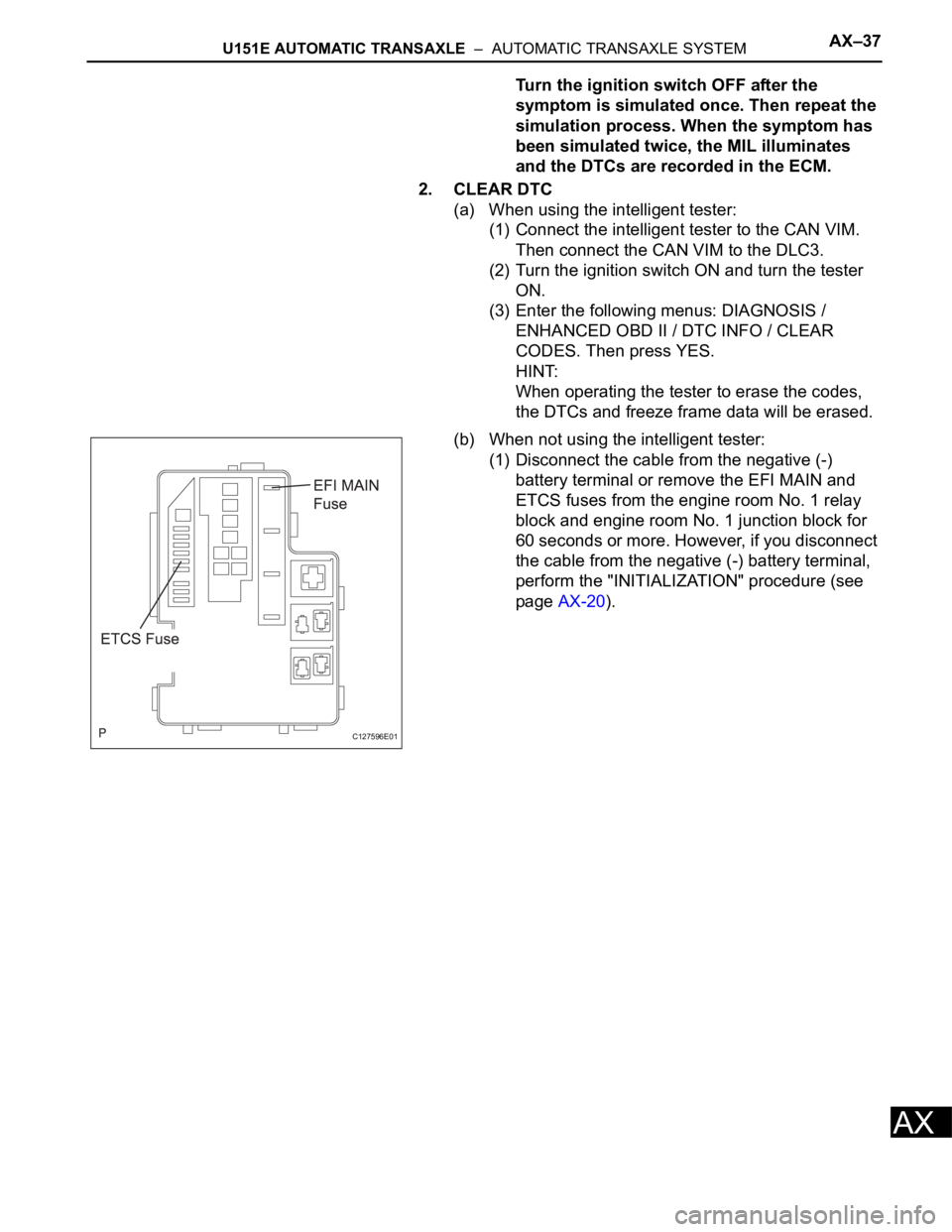
(b) When not using the intelligent tester:
(1) Disconnect the cable from the negative (-)
battery terminal or remove the EFI MAIN and
ETCS fuses from the engine room No. 1 relay
block and engine room No. 1 junction block for
60 seconds or more. However, if you disconnect
the cable from the negative (-) battery terminal,
perform the "INITIALIZATION" procedure (see
page AX-20).
C127596E01
Page 1156 of 2000
U151F AUTOMATIC TRANSAXLE – AUTOMATIC TRANSAXLE SYSTEMAX–37
AX
Turn the ignition switch OFF after the
symptom is simulated once. Then repeat the
simulation process. When the symptom has
been simulated twice, the MIL illuminates
and the DTCs are recorded in the ECM.
2. CLEAR DTC
(a) When using the intelligent tester:
(1) Connect the intelligent tester to the CAN VIM.
Then connect the CAN VIM to the DLC3.
(2) Turn the ignition switch ON and turn the tester
ON.
(3) Enter the following menus: DIAGNOSIS /
ENHANCED OBD II / DTC INFO / CLEAR
CODES. Then press YES.
HINT:
When operating the tester to erase the codes,
the DTCs and freeze frame data will be erased.
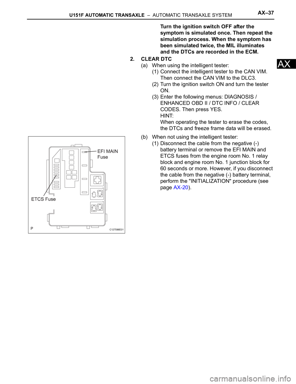
(b) When not using the intelligent tester:
(1) Disconnect the cable from the negative (-)
battery terminal or remove the EFI MAIN and
ETCS fuses from the engine room No. 1 relay
block and engine room No. 1 junction block for
60 seconds or more. However, if you disconnect
the cable from the negative (-) battery terminal,
perform the "INITIALIZATION" procedure (see
page AX-20).
C127596E01
Page 1260 of 2000
AX–36U241E AUTOMATIC TRANSAXLE – AUTOMATIC TRANSAXLE SYSTEM
AX
2. CLEAR DTC
(a) When using the intelligent tester:
(1) Connect the intelligent tester to the CAN VIM.
Then connect the CAN VIM to the DLC3.
(2) Turn the ignition switch ON and turn the tester
ON.
(3) Enter the following menus: DIAGNOSIS /
ENHANCED OBD II / DTC INFO / CLEAR
CODES. Then and press YES.
HINT:
When operating the tester to erase the codes,
the DTCs and freeze frame data will be erased.
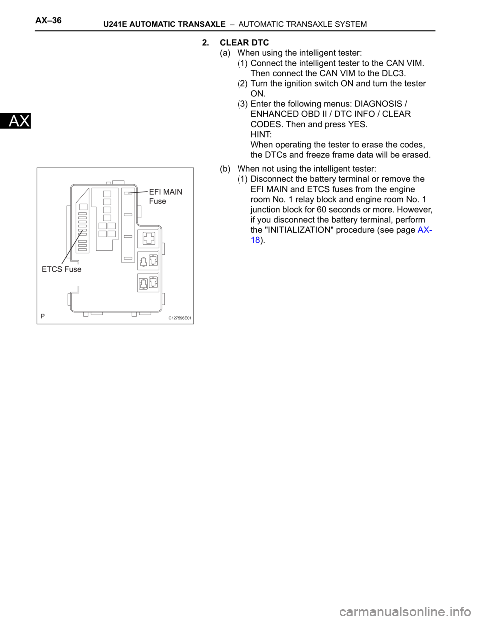
(b) When not using the intelligent tester:
(1) Disconnect the battery terminal or remove the
EFI MAIN and ETCS fuses from the engine
room No. 1 relay block and engine room No. 1
junction block for 60 seconds or more. However,
if you disconnect the battery terminal, perform
the "INITIALIZATION" procedure (see page AX-
18).
C127596E01
Page 1343 of 2000

GF1A TRANSFER – ACTIVE TORQUE CONTROL 4WD SYSTEMTF–15
TF
PROBLEM SYMPTOMS TABLE
HINT:
• Use the table below to help determine the cause of the
problem symptom. The potential causes of the symptoms
are listed in order of probability in the "Suspected area"
column of the table. Check each symptom by checking the
suspected areas in the order they are listed. Replace parts
as necessary.
• Inspect the fuses and relays related to this system before
inspecting the suspected areas below.
Active torque control 4WD system
HINT:
*:When driving 4WD mode, the vehicle is hard to turn, as if
the brakes were applied, due to the rotational difference
between the front and rear tires while turning.
Symptom Suspected area See page
Phenomenon of tight-corner braking*1.Steering angle sensor circuitTF-27
2.Linear solenoid circuitTF-30
3.4WD control ECU
4WD indicator light remains ON 4WD indicator light circuitTF-36
4WD indicator light does not come ON 4WD indicator light circuitTF-40
The system is in the DTC output mode although
terminals TC and CG of the DLC3 are not short
circuited1.TC and CG terminal circuitTF-42
2.4WD indicator light circuit
The system is not in the DTC output mode although
terminals TC and CG of the DLC3 are not short
circuited1.TC and CG terminal circuitTF-42
2.4WD indicator light circuit
Page 1490 of 2000
TW–18TIRE AND WHEEL – TIRE PRESSURE WARNING SYSTEM
TW
PROBLEM SYMPTOMS TABLE
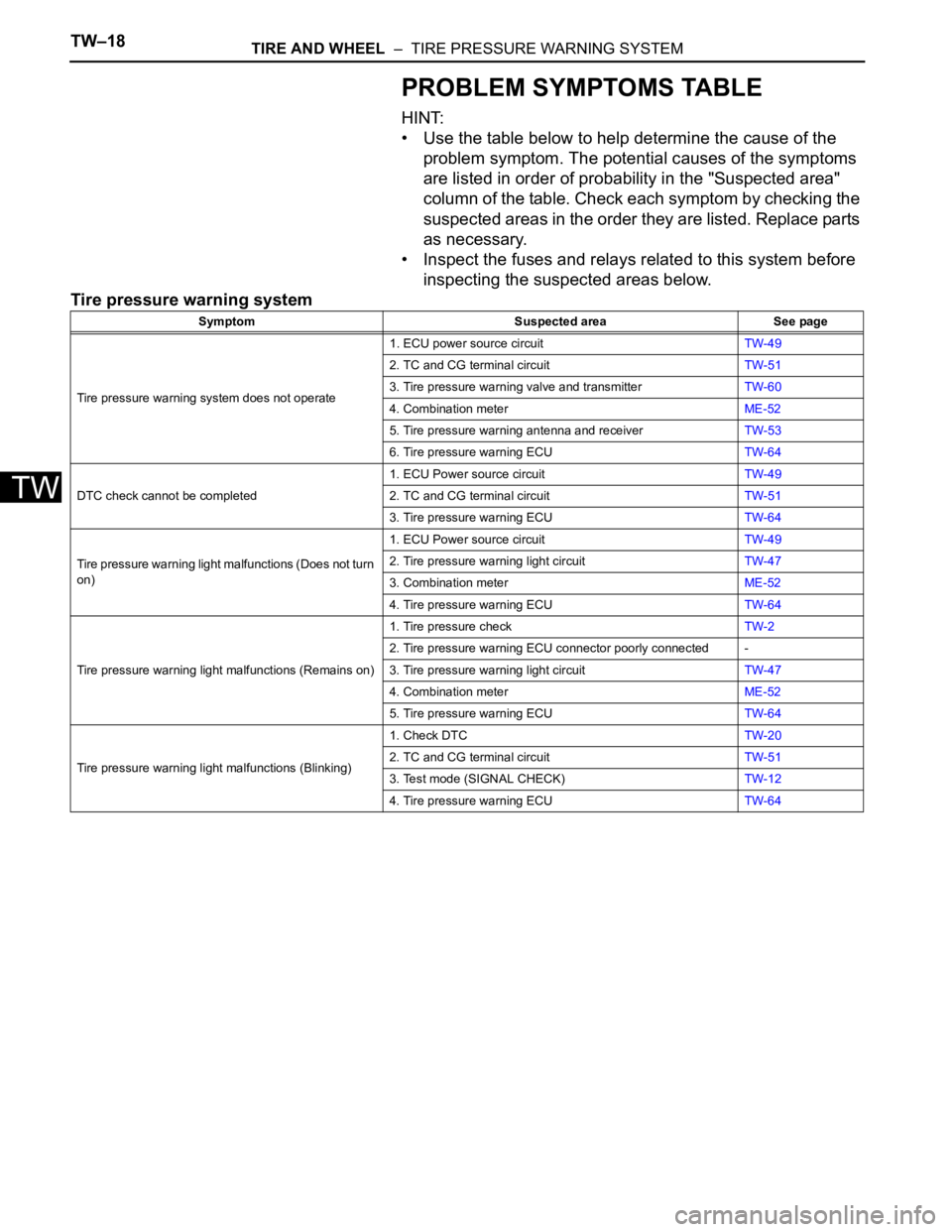
HINT:
• Use the table below to help determine the cause of the
problem symptom. The potential causes of the symptoms
are listed in order of probability in the "Suspected area"
column of the table. Check each symptom by checking the
suspected areas in the order they are listed. Replace parts
as necessary.
• Inspect the fuses and relays related to this system before
inspecting the suspected areas below.
Tire pressure warning system
Symptom Suspected area See page
Tire pressure warning system does not operate1. ECU power source circuitTW-49
2. TC and CG terminal circuitTW-51
3. Tire pressure warning valve and transmitterTW-60
4. Combination meterME-52
5. Tire pressure warning antenna and receiverTW-53
6. Tire pressure warning ECUTW-64
DTC check cannot be completed1. ECU Power source circuitTW-49
2. TC and CG terminal circuitTW-51
3. Tire pressure warning ECUTW-64
Tire pressure warning light malfunctions (Does not turn
on)1. ECU Power source circuitTW-49
2. Tire pressure warning light circuitTW-47
3. Combination meterME-52
4. Tire pressure warning ECUTW-64
Tire pressure warning light malfunctions (Remains on)1. Tire pressure checkTW-2
2. Tire pressure warning ECU connector poorly connected -
3. Tire pressure warning light circuitTW-47
4. Combination meterME-52
5. Tire pressure warning ECUTW-64
Tire pressure warning light malfunctions (Blinking)1. Check DTCTW-20
2. TC and CG terminal circuitTW-51
3. Test mode (SIGNAL CHECK)TW-12
4. Tire pressure warning ECUTW-64
Page 1545 of 2000
BC–42BRAKE CONTROL – VEHICLE STABILITY CONTROL SYSTEM
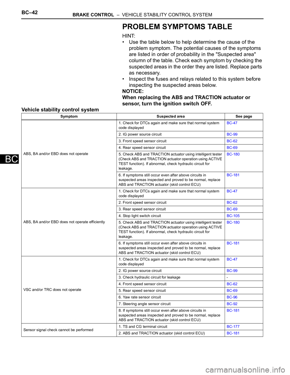
BC
PROBLEM SYMPTOMS TABLE
HINT:
• Use the table below to help determine the cause of the
problem symptom. The potential causes of the symptoms
are listed in order of probability in the "Suspected area"
column of the table. Check each symptom by checking the
suspected areas in the order they are listed. Replace parts
as necessary.
• Inspect the fuses and relays related to this system before
inspecting the suspected areas below.
NOTICE:
When replacing the ABS and TRACTION actuator or
sensor, turn the ignition switch OFF.
Vehicle stability control system
Symptom Suspected area See page
ABS, BA and/or EBD does not operate1. Check for DTCs again and make sure that normal system
code displayedBC-47
2. IG power source circuitBC-99
3. Front speed sensor circuitBC-62
4. Rear speed sensor circuitBC-69
5. Check ABS and TRACTION actuator using intelligent tester
(Check ABS and TRACTION actuator operation using ACTIVE
TEST function). If abnormal, check hydraulic circuit for
leakage.BC-180
6. If symptoms still occur even after above circuits in
suspected areas inspected and proved to be normal, replace
ABS and TRACTION actuator (skid control ECU)BC-181
ABS, BA and/or EBD does not operate efficiently1. Check for DTCs again and make sure that normal system
code displayedBC-47
2. Front speed sensor circuitBC-62
3. Rear speed sensor circuitBC-69
4. Stop light switch circuitBC-105
5. Check ABS and TRACTION actuator using intelligent tester
(Check ABS and TRACTION actuator operation using ACTIVE
TEST function). If abnormal, check hydraulic circuit for
leakage.BC-180
6. If symptoms still occur even after above circuits in
suspected areas inspected and proved to be normal, replace
ABS and TRACTION actuator (skid control ECU)BC-181
VSC and/or TRC does not operate1. Check for DTCs again and make sure that normal system
code displayedBC-47
2. IG power source circuitBC-99
3. Check hydraulic circuit for leakage -
4. Front speed sensor circuitBC-62
5. Rear speed sensor circuitBC-69
6. Yaw rate sensor circuitBC-96
7. Steering angle sensor circuitBC-92
8. If symptoms still occur even after above circuits in
suspected areas inspected and proved to be normal, replace
ABS and TRACTION actuator (skid control ECU)BC-181
Sensor signal check cannot be performed1. TS and CG terminal circuitBC-177
2. ABS and TRACTION actuator (skid control ECU)BC-181
Page 1650 of 2000
AC–22AIR CONDITIONING – AIR CONDITIONING SYSTEM (for Automatic Air Conditioning Sys-
tem)
AC
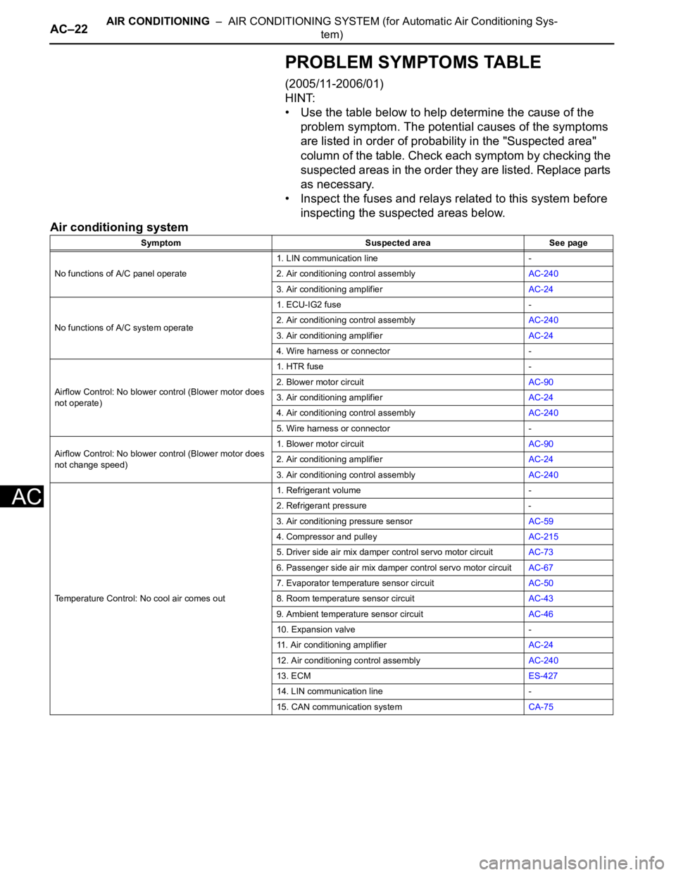
PROBLEM SYMPTOMS TABLE
(2005/11-2006/01)
HINT:
• Use the table below to help determine the cause of the
problem symptom. The potential causes of the symptoms
are listed in order of probability in the "Suspected area"
column of the table. Check each symptom by checking the
suspected areas in the order they are listed. Replace parts
as necessary.
• Inspect the fuses and relays related to this system before
inspecting the suspected areas below.
Air conditioning system
Symptom Suspected area See page
No functions of A/C panel operate1. LIN communication line -
2. Air conditioning control assemblyAC-240
3. Air conditioning amplifierAC-24
No functions of A/C system operate1. ECU-IG2 fuse -
2. Air conditioning control assemblyAC-240
3. Air conditioning amplifierAC-24
4. Wire harness or connector -
Airflow Control: No blower control (Blower motor does
not operate)1. HTR fuse -
2. Blower motor circuitAC-90
3. Air conditioning amplifierAC-24
4. Air conditioning control assemblyAC-240
5. Wire harness or connector -
Airflow Control: No blower control (Blower motor does
not change speed)1. Blower motor circuitAC-90
2. Air conditioning amplifierAC-24
3. Air conditioning control assemblyAC-240
Temperature Control: No cool air comes out1. Refrigerant volume -
2. Refrigerant pressure -
3. Air conditioning pressure sensorAC-59
4. Compressor and pulleyAC-215
5. Driver side air mix damper control servo motor circuitAC-73
6. Passenger side air mix damper control servo motor circuitAC-67
7. Evaporator temperature sensor circuitAC-50
8. Room temperature sensor circuitAC-43
9. Ambient temperature sensor circuitAC-46
10. Expansion valve -
11. Air conditioning amplifierAC-24
12. Air conditioning control assemblyAC-240
13. ECMES-427
14. LIN communication line -
15. CAN communication systemCA-75
Page 1652 of 2000
AC–24AIR CONDITIONING – AIR CONDITIONING SYSTEM (for Automatic Air Conditioning Sys-
tem)
AC
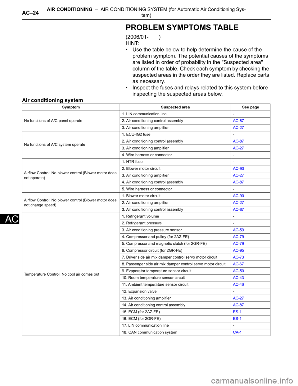
PROBLEM SYMPTOMS TABLE
(2006/01- )
HINT:
• Use the table below to help determine the cause of the
problem symptom. The potential causes of the symptoms
are listed in order of probability in the "Suspected area"
column of the table. Check each symptom by checking the
suspected areas in the order they are listed. Replace parts
as necessary.
• Inspect the fuses and relays related to this system before
inspecting the suspected areas below.
Air conditioning system
Symptom Suspected area See page
No functions of A/C panel operate1. LIN communication line -
2. Air conditioning control assemblyAC-87
3. Air conditioning amplifierAC-27
No functions of A/C system operate1. ECU-IG2 fuse -
2. Air conditioning control assemblyAC-87
3. Air conditioning amplifierAC-27
4. Wire harness or connector -
Airflow Control: No blower control (Blower motor does
not operate)1. HTR fuse -
2. Blower motor circuitAC-90
3. Air conditioning amplifierAC-27
4. Air conditioning control assemblyAC-87
5. Wire harness or connector -
Airflow Control: No blower control (Blower motor does
not change speed)1. Blower motor circuitAC-90
2. Air conditioning amplifierAC-27
3. Air conditioning control assemblyAC-87
Temperature Control: No cool air comes out1. Refrigerant volume -
2. Refrigerant pressure -
3. Air conditioning pressure sensorAC-59
4. Compressor and pulley (for 2AZ-FE)AC-79
5. Compressor and magnetic clutch (for 2GR-FE)AC-79
6. Compressor circuit (for 2GR-FE)AC-95
7. Driver side air mix damper control servo motor circuitAC-73
8. Passenger side air mix damper control servo motor circuitAC-67
9. Evaporator temperature sensor circuitAC-50
10. Room temperature sensor circuitAC-43
11. Ambient temperature sensor circuitAC-46
12. Expansion valve -
13. Air conditioning amplifierAC-27
14. Air conditioning control assemblyAC-87
15. ECM (for 2AZ-FE)ES-1
16. ECM (for 2GR-FE)ES-1
17. LIN communication line -
18. CAN communication systemCA-1