2006 TOYOTA RAV4 fuses
[x] Cancel search: fusesPage 240 of 2000
CO–42AZ-FE COOLING – COOLING FAN SYSTEM
CO
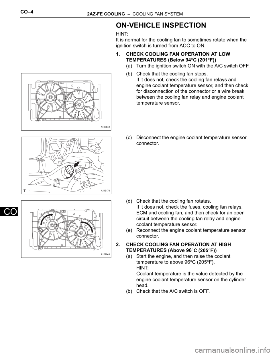
ON-VEHICLE INSPECTION
HINT:
It is normal for the cooling fan to sometimes rotate when the
ignition switch is turned from ACC to ON.
1. CHECK COOLING FAN OPERATION AT LOW
TEMPERATURES (Below 94
C (201F))
(a) Turn the ignition switch ON with the A/C switch OFF.
(b) Check that the cooling fan stops.
If it does not, check the cooling fan relays and
engine coolant temperature sensor, and then check
for disconnection of the connector or a wire break
between the cooling fan relay and engine coolant
temperature sensor.
(c) Disconnect the engine coolant temperature sensor
connector.
(d) Check that the cooling fan rotates.
If it does not, check the fuses, cooling fan relays,
ECM and cooling fan, and then check for an open
circuit between the cooling fan relay and engine
coolant temperature sensor.
(e) Reconnect the engine coolant temperature sensor
connector.
2. CHECK COOLING FAN OPERATION AT HIGH
TEMPERATURES (Above 96
C (205F))
(a) Start the engine, and then raise the coolant
temperature to above 96
C (205F).
HINT:
Coolant temperature is the value detected by the
engine coolant temperature sensor on the cylinder
head.
(b) Check that the A/C switch is OFF.
A127842
A112176
A127843
Page 339 of 2000
CH–42AZ-FE CHARGING – CHARGING SYSTEM
CH
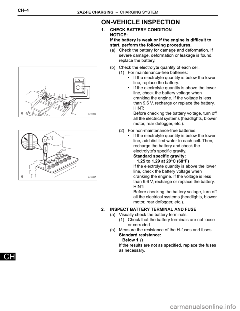
ON-VEHICLE INSPECTION
1. CHECK BATTERY CONDITION
NOTICE:
If the battery is weak or if the engine is difficult to
start, perform the following procedures.
(a) Check the battery for damage and deformation. If
severe damage, deformation or leakage is found,
replace the battery.
(b) Check the electrolyte quantity of each cell.
(1) For maintenance-free batteries:
• If the electrolyte quantity is below the lower
line, replace the battery.
• If the electrolyte quantity is above the lower
line, check the battery voltage when
cranking the engine. If the voltage is less
than 9.6 V, recharge or replace the battery.
HINT:
Before checking the battery voltage, turn off
all the electrical systems (headlights, blower
motor, rear defogger, etc.).
(2) For non-maintenance-free batteries:
• If the electrolyte quantity is below the lower
line, add distilled water to each cell. Then,
recharge the battery and check the
electrolyte's specific gravity.
Standard specific gravity:
1.25 to 1.29 at 20
C (68F)
If the electrolyte quantity is above the lower
line, check the battery voltage when
cranking the engine. If the voltage is less
than 9.6 V, recharge or replace the battery.
HINT:
Before checking the battery voltage, turn off
all the electrical systems (headlights, blower
motor, rear defogger, etc.).
2. INSPECT BATTERY TERMINAL AND FUSE
(a) Visually check the battery terminals.
(1) Check that the battery terminals are not loose
or corroded.
(b) Measure the resistance of the H-fuses and fuses.
Standard resistance:
Below 1
If the results are not as specified, replace the fuses
as necessary.
A116909
A116907
Page 495 of 2000
2AZ-FE ENGINE CONTROL SYSTEM – SFI SYSTEMES–41
ES
DTC CHECK / CLEAR
NOTICE:
When the diagnosis system is changed from normal
mode to check mode or vice versa, all DTCs and freeze
frame data recorded in normal mode are erased. Before
changing modes, always check and make a note of any
DTCs and freeze frame data.
HINT:
• DTCs which are stored in the ECM can be displayed on
the intelligent tester. The intelligent tester can display
current and pending DTCs.
• Some DTCs are not set if the ECM does not detect the
same malfunction again during a second consecutive
driving cycle. However, such malfunctions, detected on
only one occasion, are stored as pending DTCs.
1. CHECK DTC (Using intelligent tester)
(a) Connect the intelligent tester to the DLC3.
(b) Turn the ignition switch ON.
(c) Turn the tester ON.
(d) Select the following menu items: DIAGNOSIS /
ENHANCED OBD II / DTC INFO / CURRENT
CODES or PENDING CODES.
(e) Check the DTC(s) and freeze frame data, and then
write them down.
(f) Check the details of the DTC(s) (see page ES-51).
2. CLEAR DTC (Using intelligent tester)
(a) Connect the intelligent tester to the DLC3.
(b) Turn the ignition switch ON.
(c) Turn the tester ON.
(d) Select the following menu items: DIAGNOSIS /
ENHANCED OBD II / DTC INFO / CLEAR CODES.
(e) Press the YES button.
3. CLEAR DTC (Without using intelligent tester)
(a) Perform either of the following operations.
(1) Disconnect the cable from the negative (-)
battery terminal for more than 1 minute.
(2) Remove the EFI and ETCS fuses from the
engine room relay block (located inside the
engine compartment) for more than 1 minute.
Page 508 of 2000
SEAT – FRONT POWER SEAT CONTROL SYSTEMSE–3
SE
PROBLEM SYMPTOMS TABLE
HINT:
Use the table below to help determine the cause of the
problem symptom. The potential causes of the symptoms are
listed in order of probability in the "Suspected Area" column
of the table. Check each symptom by checking the suspected
areas in the order they are listed. Replace parts as
necessary.
Front power seat control system
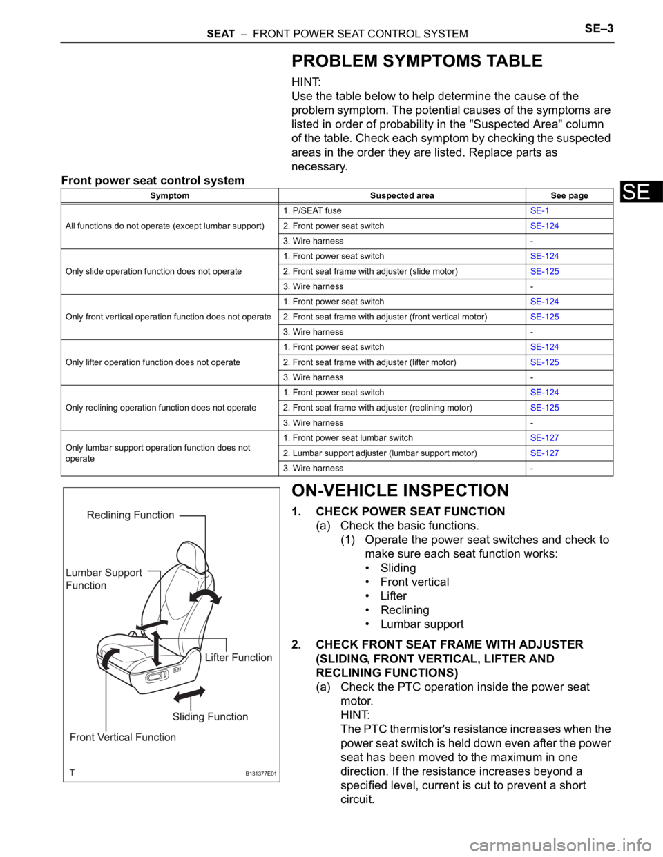
ON-VEHICLE INSPECTION
1. CHECK POWER SEAT FUNCTION
(a) Check the basic functions.
(1) Operate the power seat switches and check to
make sure each seat function works:
• Sliding
•Front vertical
•Lifter
• Reclining
• Lumbar support
2. CHECK FRONT SEAT FRAME WITH ADJUSTER
(SLIDING, FRONT VERTICAL, LIFTER AND
RECLINING FUNCTIONS)
(a) Check the PTC operation inside the power seat
motor.
HINT:
The PTC thermistor's resistance increases when the
power seat switch is held down even after the power
seat has been moved to the maximum in one
direction. If the resistance increases beyond a
specified level, current is cut to prevent a short
circuit.
Symptom Suspected area See page
All functions do not operate (except lumbar support)1. P/SEAT fuseSE-1
2. Front power seat switchSE-124
3. Wire harness -
Only slide operation function does not operate1. Front power seat switchSE-124
2. Front seat frame with adjuster (slide motor)SE-125
3. Wire harness -
Only front vertical operation function does not operate1. Front power seat switchSE-124
2. Front seat frame with adjuster (front vertical motor)SE-125
3. Wire harness -
Only lifter operation function does not operate1. Front power seat switchSE-124
2. Front seat frame with adjuster (lifter motor)SE-125
3. Wire harness -
Only reclining operation function does not operate1. Front power seat switchSE-124
2. Front seat frame with adjuster (reclining motor)SE-125
3. Wire harness -
Only lumbar support operation function does not
operate1. Front power seat lumbar switchSE-127
2. Lumbar support adjuster (lumbar support motor)SE-127
3. Wire harness -
B131377E01
Page 569 of 2000
2GR-FE ENGINE CONTROL SYSTEM – SFI SYSTEMES–45
ES
DTC CHECK / CLEAR
NOTICE:
When the diagnosis system is changed from normal
mode to check mode or vice versa, all DTCs and freeze
frame data recorded in normal mode are erased. Before
changing modes, always check and make a note of any
DTCs and freeze frame data.
HINT:
• DTCs which are stored in the ECM can be displayed on
the intelligent tester. The intelligent tester can display
current and pending DTCs.
• Some DTCs are not set if the ECM does not detect the
same malfunction again during a second consecutive
driving cycle. However, such malfunctions, detected on
only one occasion, are stored as pending DTCs.
1. CHECK DTC (Using intelligent tester)
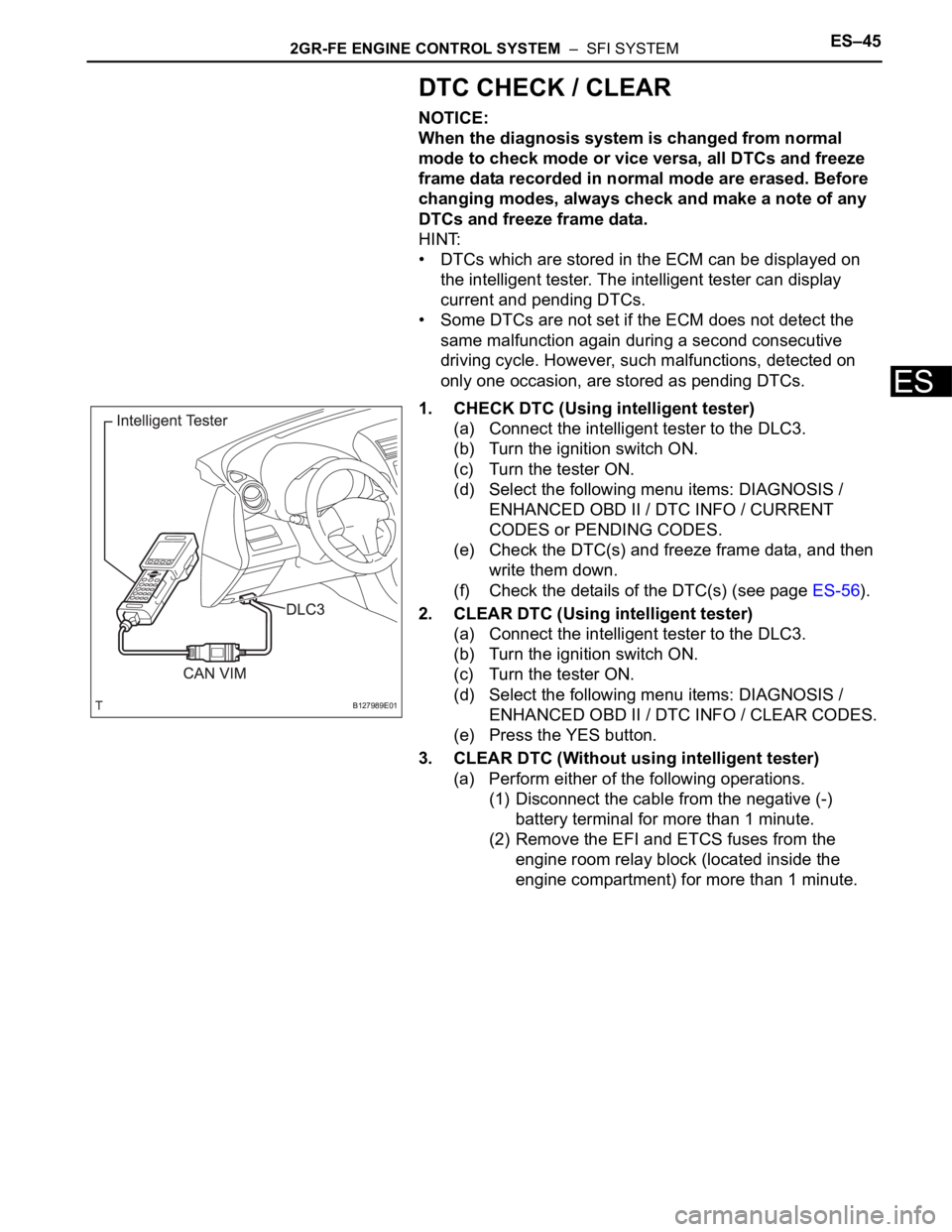
(a) Connect the intelligent tester to the DLC3.
(b) Turn the ignition switch ON.
(c) Turn the tester ON.
(d) Select the following menu items: DIAGNOSIS /
ENHANCED OBD II / DTC INFO / CURRENT
CODES or PENDING CODES.
(e) Check the DTC(s) and freeze frame data, and then
write them down.
(f) Check the details of the DTC(s) (see page ES-56).
2. CLEAR DTC (Using intelligent tester)
(a) Connect the intelligent tester to the DLC3.
(b) Turn the ignition switch ON.
(c) Turn the tester ON.
(d) Select the following menu items: DIAGNOSIS /
ENHANCED OBD II / DTC INFO / CLEAR CODES.
(e) Press the YES button.
3. CLEAR DTC (Without using intelligent tester)
(a) Perform either of the following operations.
(1) Disconnect the cable from the negative (-)
battery terminal for more than 1 minute.
(2) Remove the EFI and ETCS fuses from the
engine room relay block (located inside the
engine compartment) for more than 1 minute.
B127989E01
Page 854 of 2000

CO–62GR-FE COOLING – COOLING FAN SYSTEM
CO
ON-VEHICLE INSPECTION
HINT:
It is normal for the cooling fan to sometimes rotate when the
ignition switch is turned from ACC to ON.
1. CHECK COOLING FAN OPERATION AT LOW
TEMPERATURES (Below 94
C (201F))
(a) Turn the ignition switch ON with the A/C switch OFF.
(b) Check that the cooling fan stops.
If it does not, check the cooling fan relays and
engine coolant temperature sensor, and then check
for disconnection of the connector or wire breaks
between the cooling fan relay and engine coolant
temperature sensor.
(c) Disconnect the engine coolant temperature sensor
connector.
(d) Check that the cooling fan rotates.
If it does not, check the fuses, cooling fan relays,
ECM and cooling fan, and then check for an open
circuit between the cooling fan relay and engine
coolant temperature sensor.
(e) Reconnect the engine coolant temperature sensor
connector.
2. CHECK COOLING FAN OPERATION AT HIGH
TEMPERATURES (Above 96
C (205F))
(a) Start the engine, and then raise the coolant
temperature to above 96
C (205F).
HINT:
Coolant temperature is the value detected by the
engine coolant temperature sensor on the cylinder
head.
(b) Check that the A/C switch is OFF.
A132414
A126963
A132415
Page 928 of 2000
2GR-FE CHARGING – CHARGING SYSTEMCH–5
CH
ON-VEHICLE INSPECTION
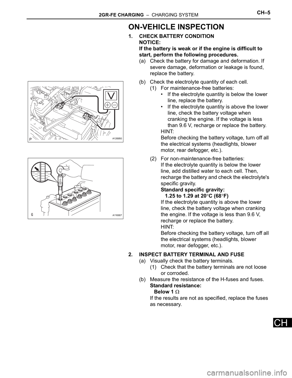
1. CHECK BATTERY CONDITION
NOTICE:
If the battery is weak or if the engine is difficult to
start, perform the following procedures.
(a) Check the battery for damage and deformation. If
severe damage, deformation or leakage is found,
replace the battery.
(b) Check the electrolyte quantity of each cell.
(1) For maintenance-free batteries:
• If the electrolyte quantity is below the lower
line, replace the battery.
• If the electrolyte quantity is above the lower
line, check the battery voltage when
cranking the engine. If the voltage is less
than 9.6 V, recharge or replace the battery.
HINT:
Before checking the battery voltage, turn off all
the electrical systems (headlights, blower
motor, rear defogger, etc.).
(2) For non-maintenance-free batteries:
If the electrolyte quantity is below the lower
line, add distilled water to each cell. Then,
recharge the battery and check the electrolyte's
specific gravity.
Standard specific gravity:
1.25 to 1.29 at 20
C (68F)
If the electrolyte quantity is above the lower
line, check the battery voltage when cranking
the engine. If the voltage is less than 9.6 V,
recharge or replace the battery.
HINT:
Before checking the battery voltage, turn off all
the electrical systems (headlights, blower
motor, rear defogger, etc.).
2. INSPECT BATTERY TERMINAL AND FUSE
(a) Visually check the battery terminals.
(1) Check that the battery terminals are not loose
or corroded.
(b) Measure the resistance of the H-fuses and fuses.
Standard resistance:
Below 1
If the results are not as specified, replace the fuses
as necessary.
A126950
A116907
Page 970 of 2000
AX–36U140F AUTOMATIC TRANSAXLE – AUTOMATIC TRANSAXLE SYSTEM
AX
2. CLEAR DTC
(a) When using the intelligent tester:
(1) Connect the intelligent tester to the CAN VIM.
Then connect the CAN VIM to the DLC3.
(2) Turn the ignition switch ON and turn the tester
ON.
(3) Enter the following menus: DIAGNOSIS /
ENHANCED OBD II / DTC INFO / CLEAR
CODES. Then and press YES.
HINT:
When operating the tester to erase the codes,
the DTCs and freeze frame data will be erased.
(b) When not using the intelligent tester:
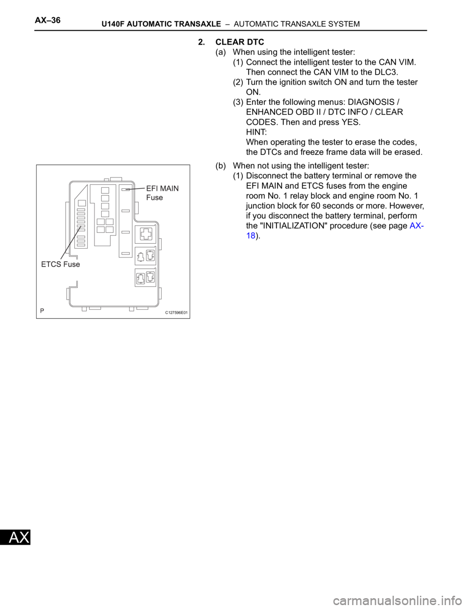
(1) Disconnect the battery terminal or remove the
EFI MAIN and ETCS fuses from the engine
room No. 1 relay block and engine room No. 1
junction block for 60 seconds or more. However,
if you disconnect the battery terminal, perform
the "INITIALIZATION" procedure (see page AX-
18).
C127596E01