Page 66 of 2000

ENGINE - 2AZ-FE ENGINE
01MEG02Y
Valve Timing : Intake Valve Opening Angle
: Exhaust Valve Opening Angle
VVT-i Operation
Range
VVT-i Operation
RangeTDC
3
3
43
65
25
45
BDCEG-3
Engine Specifications
No. of Cyls. & Arrangement4-cylinder, In-line
Valve Mechanism16-valve DOHC, Chain Drive (with VVT-i)
Combustion ChamberPentroof Type
ManifoldsCross-flow
Fuel SystemSFI
Ignition SystemDIS
Displacement cm3 (cu. in.)2362 (144.1)
Bore x Stroke mm (in.)88.5 x 96.0 (3.48 x 3.78)
Compression Ratio9.8 : 1
Max. Output*1(SAE-NET)124 kW @ 6000 rpm (166 HP @ 6000 rpm)
Max. Torque*1(SAE-NET)224 N.m @ 4000 rpm (165 ft-lbf @ 4000 rpm)
IntakeOpen3 - 43 BTDC
Valve Timing
IntakeClose65 - 25 ABDCVa l v e T i m i n g
ExhaustOpen45 BBDCExhaustClose3 ATDC
Firing Order1 - 3 - 4 - 2
Research Octane Number91 or higher
Octane Rating87 or higher
Oil GradeILSAC
Tailpipe Emission RegulationULEV-II, SFTP
Evaporative Emission RegulationLEV-II, ORVR
Engine Service Mass*2 (Reference) kg (lb)138 (304.2)
*1: Maximum output and torque rating is determined by revised SAE J1349 standard.
*
2: Weight shows the figure with oil and water fully filled.
Page 67 of 2000

ENGINE - 2GR-FE ENGINEEG-71
FEATURES OF 2GR-FE ENGINE
The 2GR-FE engine has achieved the following performance through the use of the items listed below.
(1) High performance and reliability
(2) Low noise and vibration
(3) Lightweight and compact design
(4) Good serviceability
(5) Clean emission and fuel economy
Item
(1)(2)(3)(4)(5)
A steel laminate type cylinder head gasket is used.
An upright intake port is used.
EngineA taper squish shape is used for combustion chamber.Engine
ProperA cylinder block made of aluminum alloy is used.Proper
The skirt portion of the piston is applied with resin to
reduce friction.
An oil pan No. 1 made of aluminum alloy is used.
The Dual VVT-i (Variable Valve Timing-intelligent)
system is used.
Va l v e
Mh i
Hydraulic lash adjusters are used.
MechanismTiming chains and chain tensioners are used.
Roller rocker arms are used.
Lubrication
SystemAn oil filter with a replaceable element is used.
Cooling SystemThe TOYOTA Genuine SLLC (Super Long Life Coolant)Cooling SystemThe TOYOTA Genuine SLLC (Super Long Life Coolant)
is used for the engine coolant.
The linkless-type throttle body is used.
Intake andThe intake air chamber made of plastic is used.Intake and
Exhaust
S
A stainless steel exhaust manifold is used.
SystemAn ultra thin-wall, high-cell density ceramic type TWC
(Three-Way Catalytic converter) is used.
The fuel delivery pipe made of plastic is used.
Fuel SystemA compact 12-hole type injector is used.Fuel SystemQuick connectors are used to connect the fuel hose with
the fuel pipe.
Ignition System
The DIS (Direct Ignition System) makes ignition timing
adjustment unnecessary.
Ignition System
The long-reach type spark plugs are used.
(Continued)
Page 70 of 2000

ENGINE - 2GR-FE ENGINE
285EG08 285EG07
Intake
Va l v e
Spark
Plug
Hole
Exhaust
Va l v eIntake Side
Exhaust SideCamshaft Housing
Exhaust
SideIntake
Side
Upright
Intake Port
Taper Squish A
A
View from Back Side A - A Cross Section
215EG19 215EG18
Siamese Type Independent Type EG-74
3. Cylinder Head
The cylinder head structure has been simplified by separating the cam journal portion (camshaft housing)
from the cylinder head.
The cylinder head, which is made of aluminum, contains a pentroof-type combustion chamber. The spark
plug is located in the center of the combustion chamber in order to improve the engine’s anti-knocking
performance.
The intake ports are on the inside and the exhaust ports are on the outside of the left and right banks
respectively.
Upright intake ports are used to improve the intake efficiency.
A taper squish combustion chamber is used to improve anti-knocking performance and intake efficiency.
In addition, engine performance and fuel economy have been improved.
The siamese type intake port is used to reduce the overall surface area of the intake port walls. This
prevents the fuel from adhering onto the intake port walls, thus reducing HC exhaust emissions.
— REFERENCE —
Page 72 of 2000

ENGINE - 2GR-FE ENGINE
285EG12
Liner
Cylinder
Block
Irregularly shaped
outer casting
surface of liner A
A
A - A Cross Section
285EG13
Front MarkResin CoatingTaper Squish Shape
Alumite
Coating EG-76
A compact block has been achieved by producing the thin cast-iron liners and cylinder block as a unit. It
is not possible to bore the block with this liner.
The liners are the spiny-type, which have been manufactured so that their casting exteriors form large
irregular surfaces in order to enhance the adhesion between the liners and the aluminum cylinder block.
The enhanced adhesion helps improve heat dissipation, resulting in a lower overall temperature and heat
deformation of the cylinder bores.
5. Piston
The piston is made of aluminum alloy.
The piston head portion uses a taper squish shape to accomplish fuel combustion efficiency.
The piston skirt is coated with resin to reduce the friction loss.
The groove of the top ring is coated with alumite to ensure wear resistance.
By increasing the machining precision of the cylinder bore diameter, the outer diameter of the piston is
made into one size.
Page 90 of 2000
ENGINE - 2GR-FE ENGINE
01MEG17Y
Injector
Quick Connector
Pulsation Damper
Fuel Pump Assembly
Fuel Filter
Pressure Regulator
Fuel Tank
Canister
Injector Fuel Delivery Pipe EG-94
FUEL SYSTEM
1. General
The fuel returnless system is used to reduce evaporative emissions.
A fuel cut control is used to stop the fuel pump when the SRS airbag is deployed in a frontal or side
collision. For details, see page EG-53.
The fuel delivery pipe made of plastic is used.
A quick connector is used to connect the fuel pipe with the fuel hose for excellent serviceability.
Compact 12-hole type injectors are used to increase atomization of the fuel.
A compact fuel pump in which a fuel filter is integrated in the fuel pump assembly is used.
The ORVR (On-board Refueling Vapor Recovery) system is used. For details, see page EG-131.
Page 91 of 2000
ENGINE - 2GR-FE ENGINE
01MEG34Y
Pulsation Damper
Fuel Filter
Fuel PumpPressure Regulator
Fuel Pump
Assembly
Fuel Tank
285EG38
Fuel Delivery PipesPulsation Damper
Holder
O-ring
Nylon TubeEG-95
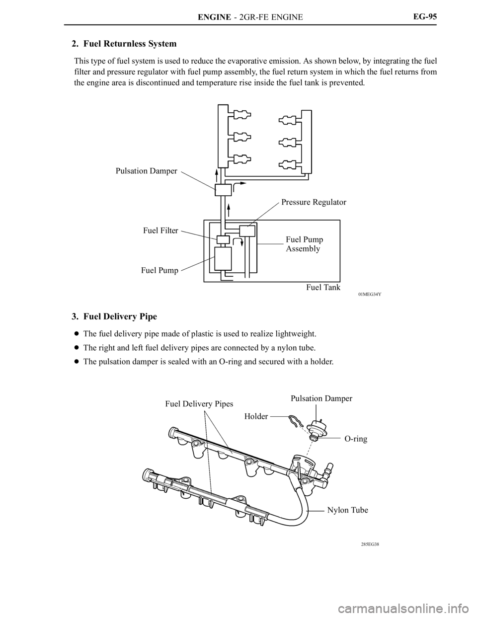
2. Fuel Returnless System
This type of fuel system is used to reduce the evaporative emission. As shown below, by integrating the fuel
filter and pressure regulator with fuel pump assembly, the fuel return system in which the fuel returns from
the engine area is discontinued and temperature rise inside the fuel tank is prevented.
3. Fuel Delivery Pipe
The fuel delivery pipe made of plastic is used to realize lightweight.
The right and left fuel delivery pipes are connected by a nylon tube.
The pulsation damper is sealed with an O-ring and secured with a holder.
Page 97 of 2000

ENGINE - 2GR-FE ENGINEEG-101
ENGINE CONTROL SYSTEM
1. General
The engine control system of the 2GR-FE engine has the following features.
System
Outline
SFI
(Sequential Multiport
Fuel Injection)
[See page EG-117]
An L-type SFI system detects the intake air mass with a hot-wire type air
flow meter.
ESA
(Electronic Spark
Advance)
Ignition timing is determined by the ECM based on signals from various
sensors. The ECM corrects ignition timing in response to engine
knocking.
This system selects the optimal ignition timing in accordance with the
signals received from the sensors and sends the (IGT) ignition signal to
the igniter.
ETCS-i
(Electronic Throttle
Control
System-intelligent)
[See page EG-118]
Optimally controls the throttle valve opening in accordance with the amount
of accelerator pedal effort and the condition of the engine and the vehicle.
Dual VVT-i
(Variable Valve
Timing-intelligent)
System
[See page EG-120]
Controls the intake and exhaust camshafts to an optimal valve timing in
accordance with the engine condition.
ACIS
(Acoustic Control
Induction System)
[See page EG-126]The intake air passages are switched according to the engine speed and
throttle valve opening angle to provided high performance in all speed
ranges.
Air Intake Control
System
[See page EG-128]The intake air duct is divided into two areas, and the ECM controls the air
intake control valve and the actuator that are provided in one of the areas to
reduce the amount of engine noise.
Fuel Pump Control
[See page EG-53 in
2AZ-FE section]Fuel pump operation is controlled by signals from the ECM.
The fuel pump is stopped, when the SRS airbag is deployed in a frontal,
side, and rear side collision.
Air Conditioning Cut-off
ControlBy turning the air conditioning compressor ON or OFF in accordance with
the engine condition, drivability is maintained.
Charging Control
[See page EG-65 in
2AZ-FE section]The engine ECU regulates the charging voltage of the generator in
accordance with the driving conditions and the charging state of the battery.
Cooling Fan Control
[See page EG-129]
The cooling fan ECU steplessly controls the speed of the fans in accordance
with the engine coolant temperature, vehicle speed, engine speed, and air
conditioning operating conditions. As a result, the cooling performance is
improved.
(Continued)
Page 105 of 2000
ENGINE - 2GR-FE ENGINEEG-109
5. Main Components of Engine Control System
General
The main components of the 2GR-FE engine control system are as follows:
Component
OutlineQuantity
ECM32-bit CPU1
Mass Air Flow MeterHot-wire Type1
Crankshaft Position Sensor (Rotor Teeth)Pick-up Coil Type (36 - 2)1
Intake VVT Sensor (Rotor Teeth)MRE (Magnetic Resistance Element)
Ty p e ( 3 )2
Exhaust VVT Sensor (Rotor Teeth)MRE (Magnetic Resistance Element)
Ty p e ( 3 )2
Accelerator Pedal Position SensorNon-contact Type1
Throttle Position SensorNon-contact Type1
Knock SensorBuilt-in Piezoelectric Type
(Non-resonant Type / Flat Type)2
Air fuel Ratio Sensor(Bank 1, Sensor 1)Type with Heater (Planar Type)1 eachAir-fuel Ratio Sensor(Bank 2, Sensor 1)Type with Heater (Planar Type)1 each
Heated Oxygen (Bank 1, Sensor 2)Type with Heater (Cup Type)1 eachHeated Oxygen
Sensor
(Bank 2, Sensor 2)Type with Heater (Cup Type)1 each
Injector12-hole Type6