2006 TOYOTA RAV4 fog light
[x] Cancel search: fog lightPage 561 of 2000

2GR-FE ENGINE CONTROL SYSTEM – SFI SYSTEMES–37
ES
HINT:
*: The ECM terminal voltage is constant regardless
of the output voltage from the sensor.
(b) WAVEFORM 1
Camshaft timing oil control valve (OCV)
PPMP (B30-77) - EPPM (B30-76) L - BR Canister pressure sensor
(built into canister pump
module)Ignition switch ON 3 to 3.6 V
ELS (A9-31) - E1 (B30-81) O - BR Electric load Taillight switch ON7.5 to 14 V
Taillight switch OFF Below 1.5 V
ELS2 (A9-33) - E1 (B30-81) G - BR Electric load Defogger switch ON7.5 to 14 V
Defogger switch OFF Below 1.5 V
ALT (B30-32) - E1 (B30-81) P - BR Generator Ignition switch ON 9 to 14 V
CANH (A9-41) - E1 (B30-81) Y - BR CAN communication line Ignition switch ON Pulse generation (see
waveform 12)
CANL (A9-49) - E1 (B30-81) W - BR CAN communication line Ignition switch ON Pulse generation (see
waveform 13)
VCIB (B30-80) - EIB (B30-101) LG - P Battery current sensor Ignition switch ON 4.5 to 5.5 V
IB (B30-100) - EIB (B30-101) R - P Battery current sensor Ignition switch ON 0.5 to 2.5 V
THB (B30-103) - EIB (B30-101) G-R - P Battery temperature
sensorIgnition switch ON, battery
temperature -30 to 80
C (-22 to
176
F)0.5 to 4.5 V
RLO (B30-31) - E1 (B30-81) Y - BR Generator After engine warmed up, during
charging control, vehicle driven at
constant speedPulse generation (see
waveform 14)
RLO (B30-31) - E1 (B30-81) Y - BR Generator After engine warmed up, during
charging control, vehicle
acceleratedPulse generation (see
waveform 15)
RLO (B30-31) - E1 (B30-81) Y - BR Generator After engine warmed up, during
charging control, vehicle
deceleratedPulse generation (see
waveform 16)
AICV (A9-4) - E1 (B30-81) L - BR VSV for air intake control
system operation signalIgnition switch ON 9 to 14 V
ACIS (B30-107) - E1 (B30-81) R - BR VSV for ACIS (Acoustic
Control Induction System)
operation signalIgnition switch ON 9 to 14 V Symbol (Terminal No.) Wiring Color Terminal Description Condition Specified Condition
A093229E02
Symbol (Terminal No.) Between OC1+ and OC1-
Between OC2+ and OC2-
Between OE1+ and OE1-
Between OE2+ and OE2-
Tester Range 5 V/DIV., 1 msec./DIV.
Condition Idling
Page 928 of 2000

2GR-FE CHARGING – CHARGING SYSTEMCH–5
CH
ON-VEHICLE INSPECTION
1. CHECK BATTERY CONDITION
NOTICE:
If the battery is weak or if the engine is difficult to
start, perform the following procedures.
(a) Check the battery for damage and deformation. If
severe damage, deformation or leakage is found,
replace the battery.
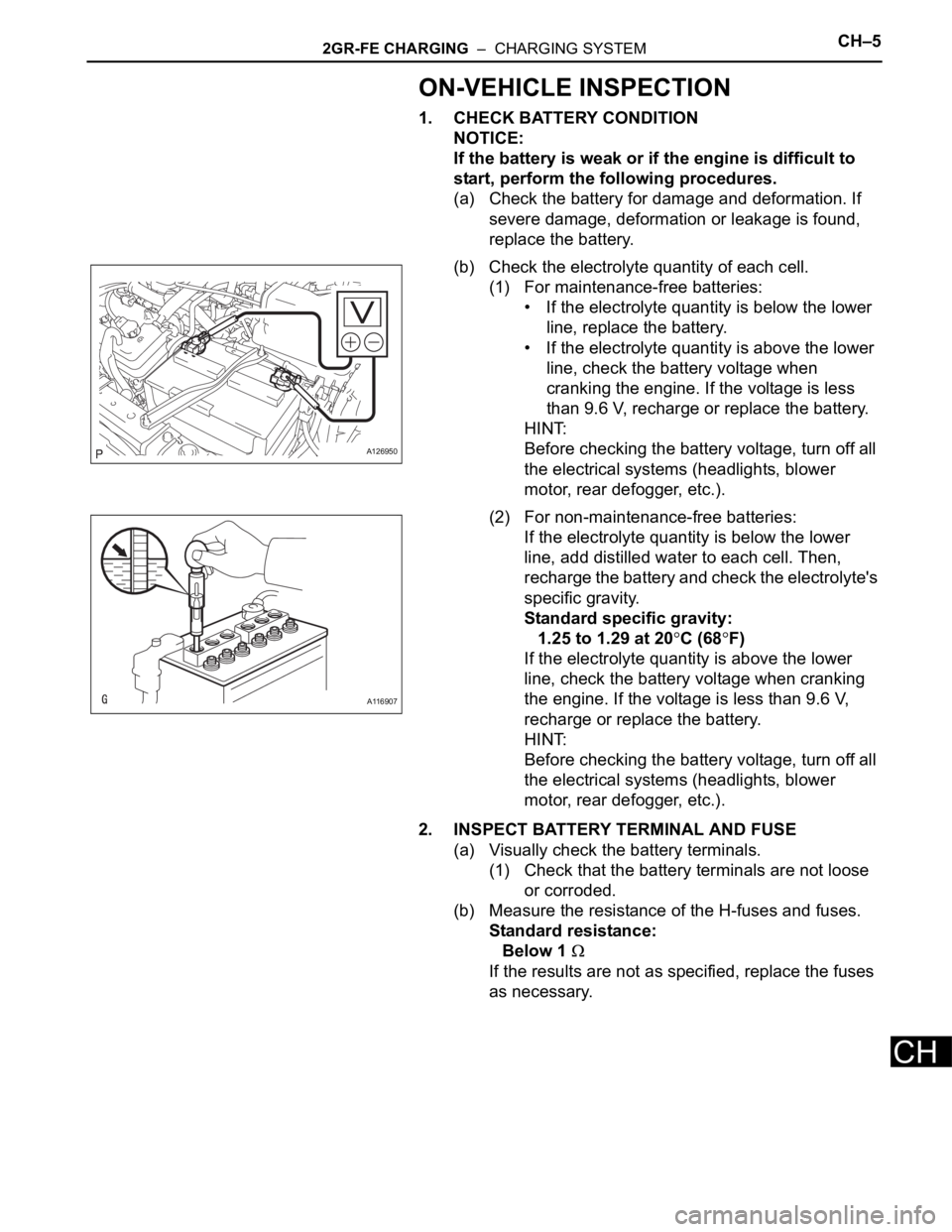
(b) Check the electrolyte quantity of each cell.
(1) For maintenance-free batteries:
• If the electrolyte quantity is below the lower
line, replace the battery.
• If the electrolyte quantity is above the lower
line, check the battery voltage when
cranking the engine. If the voltage is less
than 9.6 V, recharge or replace the battery.
HINT:
Before checking the battery voltage, turn off all
the electrical systems (headlights, blower
motor, rear defogger, etc.).
(2) For non-maintenance-free batteries:
If the electrolyte quantity is below the lower
line, add distilled water to each cell. Then,
recharge the battery and check the electrolyte's
specific gravity.
Standard specific gravity:
1.25 to 1.29 at 20
C (68F)
If the electrolyte quantity is above the lower
line, check the battery voltage when cranking
the engine. If the voltage is less than 9.6 V,
recharge or replace the battery.
HINT:
Before checking the battery voltage, turn off all
the electrical systems (headlights, blower
motor, rear defogger, etc.).
2. INSPECT BATTERY TERMINAL AND FUSE
(a) Visually check the battery terminals.
(1) Check that the battery terminals are not loose
or corroded.
(b) Measure the resistance of the H-fuses and fuses.
Standard resistance:
Below 1
If the results are not as specified, replace the fuses
as necessary.
A126950
A116907
Page 930 of 2000

2GR-FE CHARGING – CHARGING SYSTEMCH–7
CH
8. INSPECT CHARGING CIRCUIT WITH LOAD
(a) With the engine running at 2,000 rpm, turn the high
beam headlights ON and turn the heater blower
switch to the "HI" position.
(b) Check the reading on the ammeter.
Standard amperage:
30 A or more
If the ammeter reading is less than the standard
amperage, repair the generator.
HINT:
If the battery is fully charged, the indication will
sometimes be less than the standard amperage.
If this is the case, add more electrical load (operate
the wipers, rear window defogger, etc.) and check
the reading on the ammeter again.
Page 1641 of 2000

AIR CONDITIONING – AIR CONDITIONING SYSTEM (for Automatic Air Conditioning Sys-
tem)AC–13
AC
SYSTEM DESCRIPTION
1. GENERAL
(a) The air conditioning system has the following
features:
• In accordance with the temperature set using the
temperature control switch, the air conditioning
amplifier determines the outlet temperature
based on the input signals from various sensors.
In addition, corrections are made in accordance
with the signals from the water temperature
sensor to control the outlet air temperature.
• Controls the blower motor in accordance with the
airflow volume determined by the air conditioning
amplifier based on the input signals from various
sensors.
• Automatically changes the outlets in accordance
with the outlet mode ratio that is determined by
the air conditioning amplifier based on the input
signals from various sensors.
• Based on the signals from the ambient
temperature sensor, this system calculates the
outside temperature and indicates it in the multi-
information display in the combination meter
assembly.
• The left/right independent temperature control
and neural network control make air conditioner
control available to suit the persons in the driver
seat and in the passenger seat.
• Turns the rear defogger and outside rear mirror
heaters on for 15 minutes when the rear
defogger switch is pressed. Turns them off if the
switch is pressed while they are operating.
• Checks the sensors in accordance with the
operation of the air conditioner switches.
• The air conditioning amplifier has the function of
controlling the indicator lighting.
Page 1839 of 2000

LI–8LIGHTING – LIGHTING SYSTEM
LI
*2: w/ Engine immobiliser system
(c) Manual light control system:
This system functions when lights such as the
headlights and taillights are illuminated by manual
operation of the light control switch.
(1) The main body ECU receives the following
signals (D).
• Light control switch signal
• Headlight dimmer switch signal
• Front fog light switch signal
(2) The main body ECU controls the following
signals based on the signals listed in D (E).
• Headlight relay operation signal
• Taillight relay operation signal
• Daytime running light No. 2 relay operation
signal
• Daytime running light No. 3 relay operation
signal
• Daytime running light No. 4 relay operation
signal
• Front fog light relay operation signal
(3) The main body ECU controls the on/off
operation of the following parts based on the
signals listed in E.
• Headlight (LOW)
• Headlight (HIGH)
• Side marker light (front and rear)
• Front fog light
(d) Light auto turn off system:
When the headlights and taillights are illuminated by
the operation of the light control switch, if the
ignition switch is turned OFF, this system continues
illuminating the headlights and taillights for
approximately 30 seconds, and then turns off the
lights. However, when all the doors are locked
manually, using the door lock button, using the key
or pressing LOCK on the transmitter turns the
headlights and taillights off immediately.
(1) The main body ECU receives the following
signals (F).
• Door courtesy switch signal
• Ignition switch signal
(2) The main body ECU controls the following
signals based on the signals listed in F (G).
• Headlight relay operation signal
• Taillight relay operation signal
• Daytime running light No. 2 relay operation
signal
• Daytime running light No. 3 relay operation
signal
• Daytime running light No. 4 relay operation
signal
• Front fog light relay operation signal
Page 1840 of 2000

LIGHTING – LIGHTING SYSTEMLI–9
LI
(3) The main body ECU controls the illumination
period of the following parts based on the
signals listed in G.
• Headlight (LOW)
• Headlight (HIGH)
• Side marker light (front and rear)
• Front fog light
(e) Daytime running light system:
This system is directly connected to the high-beam
headlights and is designed to automatically activate
the daytime running lights in order to increase the
visibility of the vehicle.
(1) The main body ECU receives the following (H).
• Ignition switch signal
• Engine speed
• Parking brake switch signal
• Light control switch signal
(2) The main body ECU controls the following signal
based on the signals listed in H (I).
• Daytime running light No. 2 relay operation
signal
(3) The main body ECU controls the on/off
operation of the following part based on the
signal listed in I.
• Headlight (HIGH)
Page 1847 of 2000

LI–16LIGHTING – LIGHTING SYSTEM
LI
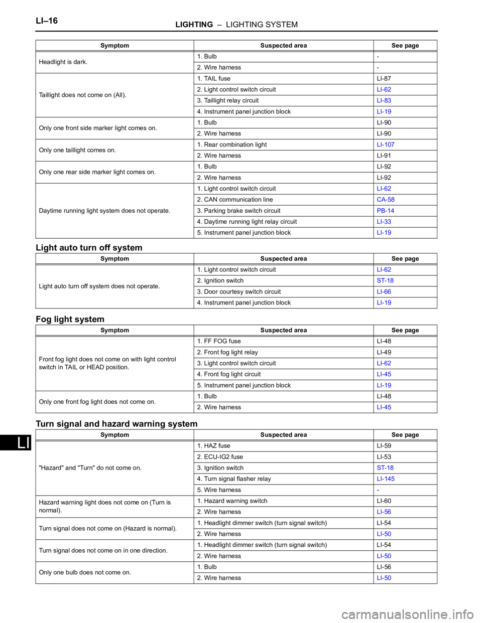
Light auto turn off system
Fog light system
Turn signal and hazard warning system
Headlight is dark.1. Bulb -
2. Wire harness -
Taillight does not come on (All).1. TAIL fuse LI-87
2. Light control switch circuitLI-62
3. Taillight relay circuitLI-83
4. Instrument panel junction blockLI-19
Only one front side marker light comes on.1. Bulb LI-90
2. Wire harness LI-90
Only one taillight comes on.1. Rear combination lightLI-107
2. Wire harness LI-91
Only one rear side marker light comes on.1. Bulb LI-92
2. Wire harness LI-92
Daytime running light system does not operate.1. Light control switch circuitLI-62
2. CAN communication lineCA-58
3. Parking brake switch circuitPB-14
4. Daytime running light relay circuitLI-33
5. Instrument panel junction blockLI-19
Symptom Suspected area See page
Light auto turn off system does not operate.1. Light control switch circuitLI-62
2. Ignition switchST-18
3. Door courtesy switch circuitLI-66
4. Instrument panel junction blockLI-19
Symptom Suspected area See page
Front fog light does not come on with light control
switch in TAIL or HEAD position.1. FF FOG fuse LI-48
2. Front fog light relay LI-49
3. Light control switch circuitLI-62
4. Front fog light circuitLI-45
5. Instrument panel junction blockLI-19
Only one front fog light does not come on.1. Bulb LI-48
2. Wire harnessLI-45
Symptom Suspected area See page
"Hazard" and "Turn" do not come on.1. HAZ fuse LI-59
2. ECU-IG2 fuse LI-53
3. Ignition switchST-18
4. Turn signal flasher relayLI-145
5. Wire harness -
Hazard warning light does not come on (Turn is
normal).1. Hazard warning switch LI-60
2. Wire harnessLI-56
Turn signal does not come on (Hazard is normal).1. Headlight dimmer switch (turn signal switch) LI-54
2. Wire harnessLI-50
Turn signal does not come on in one direction.1. Headlight dimmer switch (turn signal switch) LI-54
2. Wire harnessLI-50
Only one bulb does not come on.1. Bulb LI-56
2. Wire harnessLI-50 Symptom Suspected area See page
Page 1850 of 2000

LIGHTING – LIGHTING SYSTEMLI–19
LI
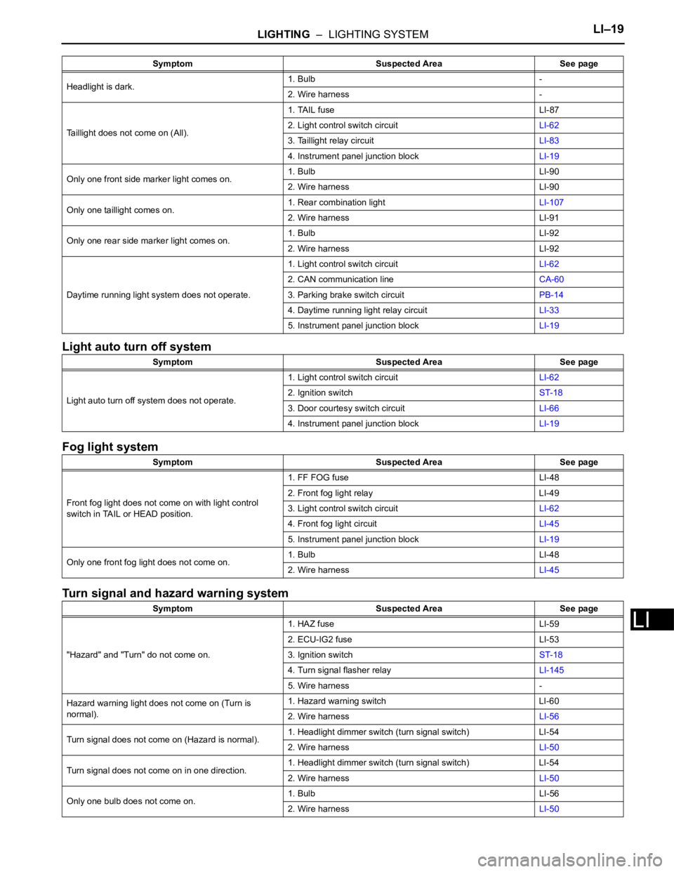
Light auto turn off system
Fog light system
Turn signal and hazard warning system
Headlight is dark.1. Bulb -
2. Wire harness -
Taillight does not come on (All).1. TAIL fuse LI-87
2. Light control switch circuitLI-62
3. Taillight relay circuitLI-83
4. Instrument panel junction blockLI-19
Only one front side marker light comes on.1. Bulb LI-90
2. Wire harness LI-90
Only one taillight comes on.1. Rear combination lightLI-107
2. Wire harness LI-91
Only one rear side marker light comes on.1. Bulb LI-92
2. Wire harness LI-92
Daytime running light system does not operate.1. Light control switch circuitLI-62
2. CAN communication lineCA-60
3. Parking brake switch circuitPB-14
4. Daytime running light relay circuitLI-33
5. Instrument panel junction blockLI-19
Symptom Suspected Area See page
Light auto turn off system does not operate.1. Light control switch circuitLI-62
2. Ignition switchST-18
3. Door courtesy switch circuitLI-66
4. Instrument panel junction blockLI-19
Symptom Suspected Area See page
Front fog light does not come on with light control
switch in TAIL or HEAD position.1. FF FOG fuse LI-48
2. Front fog light relay LI-49
3. Light control switch circuitLI-62
4. Front fog light circuitLI-45
5. Instrument panel junction blockLI-19
Only one front fog light does not come on.1. Bulb LI-48
2. Wire harnessLI-45
Symptom Suspected Area See page
"Hazard" and "Turn" do not come on.1. HAZ fuse LI-59
2. ECU-IG2 fuse LI-53
3. Ignition switchST-18
4. Turn signal flasher relayLI-145
5. Wire harness -
Hazard warning light does not come on (Turn is
normal).1. Hazard warning switch LI-60
2. Wire harnessLI-56
Turn signal does not come on (Hazard is normal).1. Headlight dimmer switch (turn signal switch) LI-54
2. Wire harnessLI-50
Turn signal does not come on in one direction.1. Headlight dimmer switch (turn signal switch) LI-54
2. Wire harnessLI-50
Only one bulb does not come on.1. Bulb LI-56
2. Wire harnessLI-50 Symptom Suspected Area See page