2006 TOYOTA RAV4 fog light
[x] Cancel search: fog lightPage 101 of 2000

ENGINE - 2GR-FE ENGINE
01MEG08Y
DEFOGGER RELAY
TA I L L A M P R E L AY
STOP LIGHT SWITCH
CRUISE CONTROL SWITCH
AIR CONDITIONING ECU
AIRBAG SENSOR
ASSEMBLY
SKID CONTROL ECU
DLC3
MAIN RELAY
BATTERYELS
ELS2
STP
CCS
CANH,
CANL
TC
TA C H
MREL
+B
BATTECMRFC
RFC
MPMP
VPMP
PRG
WCOOLING FAN CONTROL*1
COOLING FAN ECU
FAN MOTOR NO. 1 AND
NO. 2
COOLING FAN CONTROL*
2
COOLING FAN ECU NO. 1
FAN MOTOR NO. 1
COOLING FAN ECU NO. 2
FAN MOTOR NO. 2
EVAPORATIVE EMISSION
CONTROL
LEAK DETECTION
PUMP
VENT VALVE
PURGE VSV
COMBINATION METER
MIL
: CANEG-105
*
1: Except Towing Package Models
*
2: Towing Package Models
Page 209 of 2000

IN–26INTRODUCTION – REPAIR INSTRUCTION
IN
CUSTOMIZE PARAMETERS
NOTICE:
• When the customer requests a change in a function,
first make sure that the function can be customized.
• Make a note of the current settings before
customizing.
• When troubleshooting a function, first make sure that
the function is set to the default setting.
1. Combination meter
2. Air conditioning system
3. Power Door Lock Control System
4. Wireless Door Lock Control System
Display (Item) Default Function Setting
SEAT BELT WARN D/P ON Seat belt warning buzzer ON /
OFF settingD/P ON: Driver and passenger
buzzer ON
D ON: Driver buzzer ON
P ON: Passenger buzzer ON
D/P OFF: Driver and passenger
buzzer OFF
Display (Item) Default Contents Setting
SET TEMP SHIFT
(Set Temperature Shift)NORMALTo control with shifted temperature against
display temperature+2 C / +1 C / NORMAL / -1 C / -2
C
AIR INLET MODE
(Air Inlet Mode)AUTOIn case of turning A/C ON when you desire to
make compartment cool down quickly, this is
function to change mode automatically to
RECIRCULATION modeMANUAL / AUTO
COMPRESSOR MODE
(Compressor Mode)AUTOFunction to turn A/C ON automatically by
pressing AUTO button when blower is ON
and A/C is OFFMANUAL / AUTO
COMPRS / DEF OPER
(Compressor / Air Inlet DEF
Operation)LINKFunction to turn A/C ON automatically linked
with FRONT DEF button when A/C is OFFNORMAL / LINK
EVAP CTRL
(Evaporator Control)AUTOFunction to set evaporator control to
AUTOMATIC position (AUTO) to save power,
or to coldest position (MANUAL) to dehumidify
air and to prevent windows from fogging upMANUAL / AUTO
FOOT / DEF MODE
(Foot / DEF auto mode)ONFunction to turn airflow from FOOT / DEF ON
automatically when AUTO MODE is ONOFF / ON
AUTO BLOW UP
(Foot / DEF automatic blower up
function)ONFunction to change blower level automatically
when defroster is ONOFF / ON
Display (Item) Default Function Setting
UNLK/KEY TWICE ON Unlocks only driver side door
when driver side door key
cylinder turned to unlock once,
and unlocks all doors when
turned to unlock twice. For OFF
setting, turning it once unlocks all
doors.ON / OFF
Display (Item) Default Contents Setting
HAZARD ANS BACK ONWhen LOCK switch on
transmitter pressed, all hazard
warning lights illuminate once.
When UNLOCK switch pressed,
all hazard warning lights
illuminate twiceON / OFF
Page 339 of 2000

CH–42AZ-FE CHARGING – CHARGING SYSTEM
CH
ON-VEHICLE INSPECTION
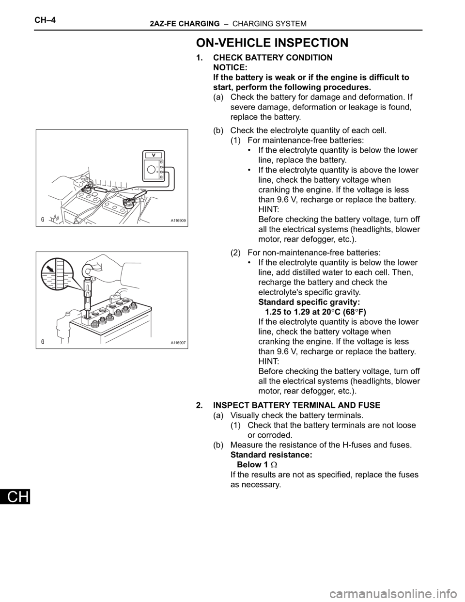
1. CHECK BATTERY CONDITION
NOTICE:
If the battery is weak or if the engine is difficult to
start, perform the following procedures.
(a) Check the battery for damage and deformation. If
severe damage, deformation or leakage is found,
replace the battery.
(b) Check the electrolyte quantity of each cell.
(1) For maintenance-free batteries:
• If the electrolyte quantity is below the lower
line, replace the battery.
• If the electrolyte quantity is above the lower
line, check the battery voltage when
cranking the engine. If the voltage is less
than 9.6 V, recharge or replace the battery.
HINT:
Before checking the battery voltage, turn off
all the electrical systems (headlights, blower
motor, rear defogger, etc.).
(2) For non-maintenance-free batteries:
• If the electrolyte quantity is below the lower
line, add distilled water to each cell. Then,
recharge the battery and check the
electrolyte's specific gravity.
Standard specific gravity:
1.25 to 1.29 at 20
C (68F)
If the electrolyte quantity is above the lower
line, check the battery voltage when
cranking the engine. If the voltage is less
than 9.6 V, recharge or replace the battery.
HINT:
Before checking the battery voltage, turn off
all the electrical systems (headlights, blower
motor, rear defogger, etc.).
2. INSPECT BATTERY TERMINAL AND FUSE
(a) Visually check the battery terminals.
(1) Check that the battery terminals are not loose
or corroded.
(b) Measure the resistance of the H-fuses and fuses.
Standard resistance:
Below 1
If the results are not as specified, replace the fuses
as necessary.
A116909
A116907
Page 341 of 2000

CH–62AZ-FE CHARGING – CHARGING SYSTEM
CH
8. INSPECT CHARGING CIRCUIT WITH LOAD
(a) With the engine running at 2,000 rpm, turn the high
beam headlights ON and turn the heater blower
switch to the "HI" position.
(b) Check the reading on the ammeter.
Standard amperage:
30 A or more
If the ammeter reading is less than the standard
amperage, repair the generator.
HINT:
If the battery is fully charged, the indication will
sometimes be less than the standard amperage. If
this is the case, add more electrical load (operate
the wipers, rear window defogger, etc.) and check
the reading on the ammeter again.
Page 487 of 2000

2AZ-FE ENGINE CONTROL SYSTEM – SFI SYSTEMES–33
ES
HINT:
*: The ECM terminal voltage is constant regardless of the
output voltage from the sensor.
M- (B30-41) - ME01 (B30-43) W - W-B Throttle actuator Idling with warm enginePulse generation (see
waveform 10)
FC (A9-7) - E1 (B30-104) W - BR Fuel pump controlIgnition switch ON 9 to 14 V
Idling Below 1.5 V
W (A9-24) - E1 (B30-104) R - BR MILIgnition switch ON Below 1.5 V
Idling 9 to 14 V
TC (A9-27) - E1 (B30-104) G - BR Terminal TC of DLC3 Ignition switch ON 9 to 14 V
TACH (A9-15) - E1 (B30-104) GR - BR Engine speed IdlingPulse generation (see
waveform 11)
VPMP (A9-42) - E1 (B30-104) W - BRVent valve (built into
canister pump module)Ignition switch ON 9 to 14 V
MPMP (A9-34) - E1 (B30-104) B - BRLeak detection pump (built
into canister pump
module)Leak detection pump OFF Below 3 V
Leak detection pump ON 9 to 14 V
VCPP (B30-70) - EPPM (B30-94) Y - BRPower source for canister
pressure sensor (specific
voltage)Ignition switch ON 4.5 to 5.5 V
PPMP (B30-71) - EPPM (B30-94) V - BRCanister pressure sensor
(built into canister pump
module)Ignition switch ON 3 to 3.6 V
ELS1 (A9-31) - E1 (B30-104) O - BR Electric loadTaillight switch ON 7.5 to 14 V
Taillight switch OFF Below 1.5 V
ELS3 (A9-33) - E1 (B30-104) G - BR Electric loadDefogger switch ON 7.5 to 14 V
Defogger switch OFF Below 1.5 V
FANL (A9-21) - E1 (B30-104) R - BR Fan No. 1 relayIgnition switch ON 9 to 14 V
Idling with A/C ON, or high engine
coolant temperatureBelow 1.5 V
FANH (A9-22) - E1 (B30-104) W - BR Fan No. 2 relayIdling with high engine coolant
temperatureBelow 1.5 V
ALT (B30-50) - E1 (B30-104) B - BR Generator Ignition switch ON 9 to 14 V
CANH (A9-41) - E1 (B30-104) Y - BR CAN communication line Ignition switch ONPulse generation (see
waveform 12)
CANL (A9-49) - E1 (B30-104) W - BR CAN communication line Ignition switch ONPulse generation (see
waveform 13)
VCIB (B30-69) - EIB (B30-92) R - BR Battery current sensor Ignition switch ON 4.5 to 5.5 V
IB (B30-68) - EIB (B30-92) B - BR Battery current sensor Ignition switch ON 0.5 to 2.5 V
THB (B30-120) - EIB (B30-92) LG - BRBattery temperature
sensorIgnition switch ON, Battery
temperature -30 to 80
C (-22 to
176
F)0.5 to 4.5 V
RLO (B30-51) - E1 (B30-104) GR - BR GeneratorAfter engine warmed up, during
charging control, vehicle driven at
constant speedPulse generation (see
waveform 14)
RLO (B30-51) - E1 (B30-104) GR - BR GeneratorAfter engine warmed up, during
charging control, vehicle
acceleratedPulse generation (see
waveform 15)
RLO (B30-51) - E1 (B30-104) GR - BR GeneratorAfter engine warmed up, during
charging control, vehicle
deceleratedPulse generation (see
waveform 16) Symbols (Terminal No.) Wiring Colors Terminal Descriptions ConditionsSpecified
Conditions
Page 511 of 2000

EXTERIOR – FRONT BUMPERET–5
ET
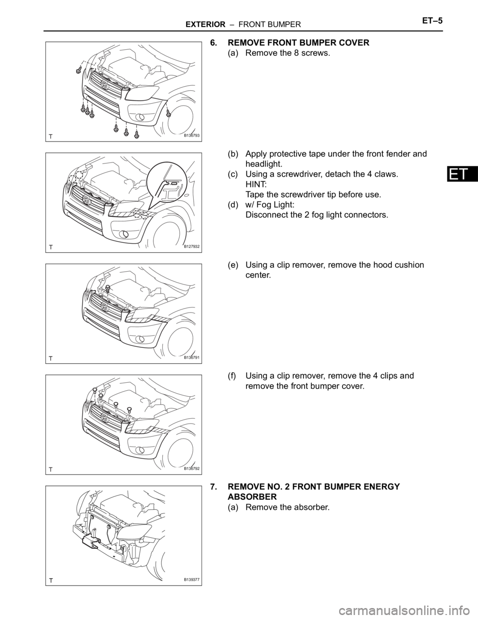
6. REMOVE FRONT BUMPER COVER
(a) Remove the 8 screws.
(b) Apply protective tape under the front fender and
headlight.
(c) Using a screwdriver, detach the 4 claws.
HINT:
Tape the screwdriver tip before use.
(d) w/ Fog Light:
Disconnect the 2 fog light connectors.
(e) Using a clip remover, remove the hood cushion
center.
(f) Using a clip remover, remove the 4 clips and
remove the front bumper cover.
7. REMOVE NO. 2 FRONT BUMPER ENERGY
ABSORBER
(a) Remove the absorber.
B136793
B127932
B136791
B136792
B139377
Page 514 of 2000

ET–8EXTERIOR – FRONT BUMPER
ET
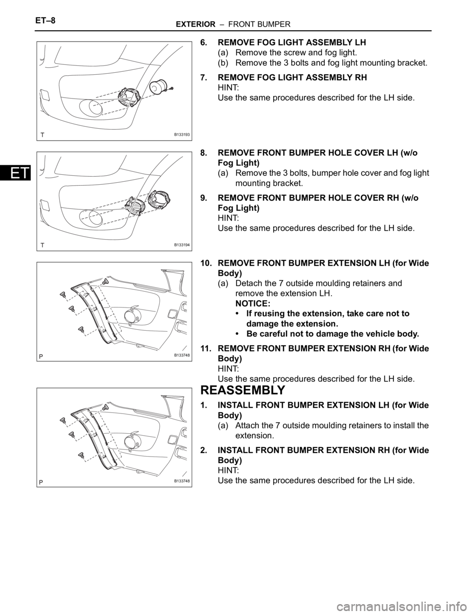
6. REMOVE FOG LIGHT ASSEMBLY LH
(a) Remove the screw and fog light.
(b) Remove the 3 bolts and fog light mounting bracket.
7. REMOVE FOG LIGHT ASSEMBLY RH
HINT:
Use the same procedures described for the LH side.
8. REMOVE FRONT BUMPER HOLE COVER LH (w/o
Fog Light)
(a) Remove the 3 bolts, bumper hole cover and fog light
mounting bracket.
9. REMOVE FRONT BUMPER HOLE COVER RH (w/o
Fog Light)
HINT:
Use the same procedures described for the LH side.
10. REMOVE FRONT BUMPER EXTENSION LH (for Wide
Body)
(a) Detach the 7 outside moulding retainers and
remove the extension LH.
NOTICE:
• If reusing the extension, take care not to
damage the extension.
• Be careful not to damage the vehicle body.
11. REMOVE FRONT BUMPER EXTENSION RH (for Wide
Body)
HINT:
Use the same procedures described for the LH side.
REASSEMBLY
1. INSTALL FRONT BUMPER EXTENSION LH (for Wide
Body)
(a) Attach the 7 outside moulding retainers to install the
extension.
2. INSTALL FRONT BUMPER EXTENSION RH (for Wide
Body)
HINT:
Use the same procedures described for the LH side.
B133193
B133194
B133748
B133748
Page 515 of 2000

EXTERIOR – FRONT BUMPERET–9
ET
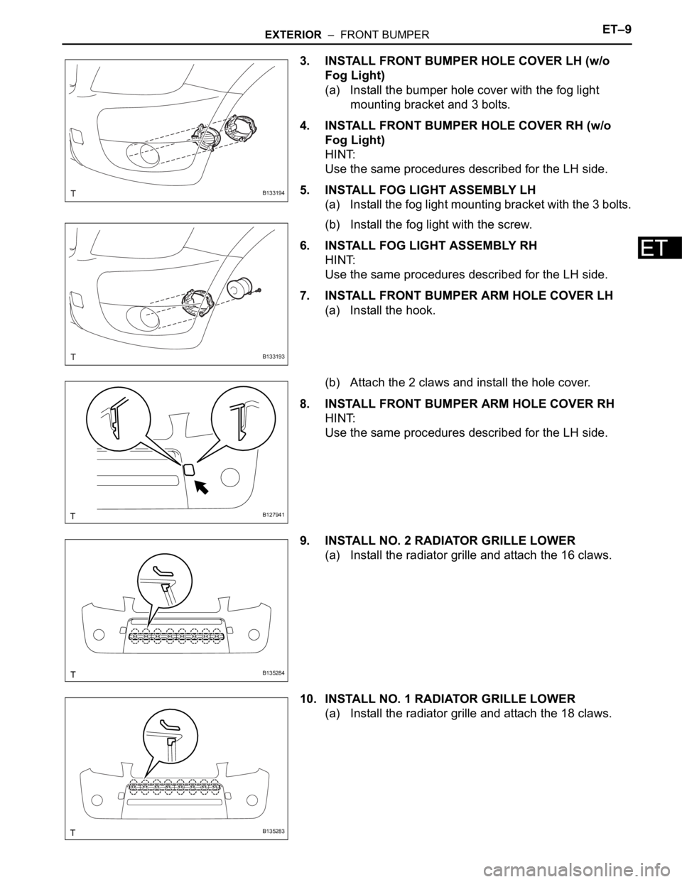
3. INSTALL FRONT BUMPER HOLE COVER LH (w/o
Fog Light)
(a) Install the bumper hole cover with the fog light
mounting bracket and 3 bolts.
4. INSTALL FRONT BUMPER HOLE COVER RH (w/o
Fog Light)
HINT:
Use the same procedures described for the LH side.
5. INSTALL FOG LIGHT ASSEMBLY LH
(a) Install the fog light mounting bracket with the 3 bolts.
(b) Install the fog light with the screw.
6. INSTALL FOG LIGHT ASSEMBLY RH
HINT:
Use the same procedures described for the LH side.
7. INSTALL FRONT BUMPER ARM HOLE COVER LH
(a) Install the hook.
(b) Attach the 2 claws and install the hole cover.
8. INSTALL FRONT BUMPER ARM HOLE COVER RH
HINT:
Use the same procedures described for the LH side.
9. INSTALL NO. 2 RADIATOR GRILLE LOWER
(a) Install the radiator grille and attach the 16 claws.
10. INSTALL NO. 1 RADIATOR GRILLE LOWER
(a) Install the radiator grille and attach the 18 claws.
B133194
B133193
B127941
B135284
B135283