2006 SUZUKI SX4 stop start
[x] Cancel search: stop startPage 957 of 1556

Downloaded from www.Manualslib.com manuals search engine Air Conditioning System: Manual Type 7B-17
Repair Instructions
Operation Procedure for Refrigerant ChargeS6RW0D7216001
WARNING!
• Your eyes should not be exposed to refrigerant (liquid).
Any liquid HFC-134a (R-134a) escaping by accident shows a temperature as low as approximately –
6 °C (21.2 °F) below freezing point. Should liquid HFC-134a (R-134a) is exposed to your eyes, it may
cause a serious injury. To protect your eyes from such accident, it is necessary to always wear
goggles. Should it occur that HFC-134a (R-134a) is exposed to your eyes, consult a doctor
immediately.
– Do not use your hand to rub the affected eye(s). Instead, use fresh cold water to splash it over the
affected area to gradually raise temperature of such area above freezing point.
– Obtain proper treatment as soon as possible from a doctor or eye specialist.
• Should the liquid refrigerant HFC-134a (R-134a) is exposed to your skin, the affected area should be
treated in the same manner as when skin is frostbitten or frozen.
• Do not handle refrigerant near any place where welding or steam cleaning is performed.
• Refrigerant should be kept in a cold and dark place. It should never be stored in any place where
temperature is high, e.g. where exposed to direct sun light, close to fire or inside vehicle (including
trunk room).
• Avoid breathing fume produced when HFC-134a (R-134a) is burned. Such fume may be hazardous to
your health.
Start evacuation.Start evacuation.
Stop evacuation.Stop evacuation.
15 minutes (above -100 kPa)15 minutes (above -100 kPa)
Wait 10 minutesWait 10 minutes
Check A/C system forCheck A/C system for
pressure tighteness.pressure tighteness.
Recharge A/C system withRecharge A/C system withrefrigerant.refrigerant.
Check A/C system for refrigerantCheck A/C system for refrigerantleaks and amount of refrigerantleaks and amount of refrigerantcharged.charged.
Performance testPerformance test
Inspect and repair connections.Inspect and repair connections.
If gauge showsIf gauge showsabnormal conditionsabnormal conditions
Recharge 430 20 g ofRecharge 430 20 g ofrefrigerant.refrigerant.
I5RW0A721011-01
Page 960 of 1556

Downloaded from www.Manualslib.com manuals search engine 7B-20 Air Conditioning System: Manual Type
Charge
CAUTION!
• Because the sight glass is not used for this
A/C system, do not perform an additional
charge to the A/C system. To charge the
proper amount of refrigerant, recover and
evacuate the A/C system first. And then,
charge the proper amount of refrigerant
into the A/C system.
• Always charge refrigerant through low
pressure side of A/C system after the initial
charge is performed from the high
pressure side with the engine stopped.
• Never charge refrigerant through high
pressure side of A/C system with engine
running.
• Do not charge refrigerant while
compressor is hot.
• When installing tap valve to refrigerant
container to make a hole there through,
carefully follow directions given by
manufacturer.
• A pressure gauge should always be used
before and during refrigerant charge.
• The refrigerant container should be
emptied of refrigerant when discarding it.
• The refrigerant container should not be
heated up to 40 °C (104 °F) or over.
• Refrigerant container should not be
reversed in direction during refrigerant
charge. Reversing in direction causes
liquid refrigerant to enter compressor,
causing troubles, such as compression of
liquid refrigerant and the like.
NOTE
The air conditioning system contains HFC-
134a (R-134a).
Described here is a method to charge the air
conditioning system with refrigerant from the
refrigerant service container.
When charging refrigerant recovered by
using the refrigerant and recycling
equipment (when recycling refrigerant),
follow the procedure described in the
equipment manufacturer’s instruction
manual.
The initial charge of the A/C system is performed
through the high pressure side with the engine stopped.
And next, this method must be followed by charging from
the low pressure side with the engine running.
1) Check if hoses are routed properly after evacuating
the system.
2) Connect low charging hose (1) and high charging
hose (2) of the manifold gauge set (3) in position.
Then, open refrigerant container valve (4) to purge
the charging line.
3) Open the high pressure side valve (5) and charge
refrigerant to system.
4) After a while, open the low pressure side valve (6)
and close the high pressure side valve.
WARNING!
Make sure that high pressure side valve is
closed securely.
5) Start engine and keep engine speed at 1500 r/min,
and then operate A/C system.
6) Charge A/C system with refrigerant in vapor state. At
this time, refrigerant container should be held
upright.
4
3
6
2
1 5
I7RW01721012-01
Page 1036 of 1556

Downloaded from www.Manualslib.com manuals search engine 8A-5 Seat Belts:
Front Seat Belt Removal and InstallationS6RW0D8106002
WARNING!
• Never attempt to disassemble or repair the
retractor (seat belt pretensioner). If any
abnormality is found, be sure to replace it
with new one as an assembly.
• Be sure to read “Precautions on Service
and Diagnosis of Seat Belt” before starting
to work and observe every precaution
during work. Neglecting them may result in
personal injury or unactivation of the seat
belt pretensioner when necessary.
Removal
1) Disconnect negative (–) cable at battery.
2) Disable air bag system. Refer to “Disabling Air Bag
System in Section 8B”.
3) Remove center pillar lower trim.
4) Disconnect connector (1) from retractor (seat belt
pretensioner) (2) as following steps.
a) Unlock lock button (3) by pulling it.
b) After unlocked, disconnect connector.
5) Remove front seat belts from the vehicle.Installation
Install in reverse order of removal, noting the following.
• Seat belt anchor bolts should have an unified fine
thread (7/16-20 UNF). Under no circumstances
should any different sized or metric screw threads be
used.
• Connect seat belt pretensioner connector (1) to
retractor (seat belt pretensioner) securely as following
steps.
a. Make sure that lock button (2) is unlock position.
b. Insert connector to retractor (seat belt
pretensioner) until it stops with unlocked lock
button (2).
c. Lock connector securely by showing in lock button
(2).
• Enable air bag system. Refer to “Enabling Air Bag
System in Section 8B”.
2
1
3
I5RW0A810002-02
1
2
I5RW0A810003-03
Page 1039 of 1556

Downloaded from www.Manualslib.com manuals search engine Seat Belts: 8A-8
Rear Seat Belt Removal and InstallationS6RW0D8106005
WARNING!
Be sure to read “Precautions on Service and
Diagnosis of Seat Belt” before starting to
work and observe every precaution during
work.
Removal
1) Fold rear seats referring to “Folding Rear Seats” in
Owners Manual.
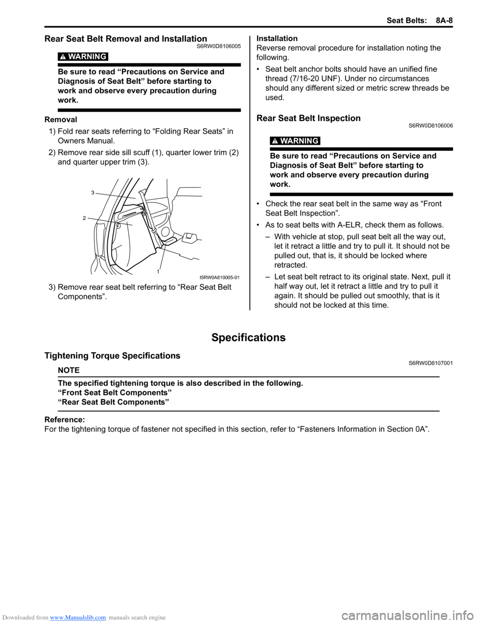
2) Remove rear side sill scuff (1), quarter lower trim (2)
and quarter upper trim (3).
3) Remove rear seat belt referring to “Rear Seat Belt
Components”.Installation
Reverse removal procedure for installation noting the
following.
• Seat belt anchor bolts should have an unified fine
thread (7/16-20 UNF). Under no circumstances
should any different sized or metric screw threads be
used.Rear Seat Belt InspectionS6RW0D8106006
WARNING!
Be sure to read “Precautions on Service and
Diagnosis of Seat Belt” before starting to
work and observe every precaution during
work.
• Check the rear seat belt in the same way as “Front
Seat Belt Inspection”.
• As to seat belts with A-ELR, check them as follows.
– With vehicle at stop, pull seat belt all the way out,
let it retract a little and try to pull it. It should not be
pulled out, that is, it should be locked where
retracted.
– Let seat belt retract to its original state. Next, pull it
half way out, let it retract a little and try to pull it
again. It should be pulled out smoothly, that is it
should not be locked at this time.
Specifications
Tightening Torque SpecificationsS6RW0D8107001
NOTE
The specified tightening torque is also described in the following.
“Front Seat Belt Components”
“Rear Seat Belt Components”
Reference:
For the tightening torque of fastener not specified in this section, refer to “Fasteners Information in Section 0A”.
1 23I5RW0A810005-01
Page 1136 of 1556

Downloaded from www.Manualslib.com manuals search engine 8B-97 Air Bag System:
Driver Air Bag (Inflator) Module InspectionS6RW0D8206006
WARNING!
Never disassemble air bag (inflator) module
or measure its resistance. Otherwise,
personal injury may result.
CAUTION!
If air bag (inflator) module was dropped from
a height of 90 cm (3 ft) or more, it should be
replaced.
Check air bag (inflator) module visually and if any of the
following is found, replace it with a new one.
• Air bag being deployed
• Trim cover (pad surface) (1) being cracked
• Inflator case (2) being damaged or having been
exposed to strong impact (dropped)
• Bend or deformity of air bag (inflator) module bracket.
Passenger Air Bag (Inflator) Module Removal
and Installation
S6RW0D8206007
WARNING!
• Never attempt to disassemble or repair the
passenger air bag (inflator) module. If any
abnormality is found, be sure to replace it
with new one as an assembly.
• Be sure to read “Precautions on Service
and Diagnosis of Air Bag System”,
“Precautions on Handling and Storage of
Air Bag System Components” and
“Precautions on Disposal of Air Bag and
Seat Belt Pretensioner” before starting to
work and observe every precaution during
work. Neglecting them may result in
personal injury or undeployment of the air
bag when necessary.
Removal
1) Disable air bag system. Refer to “Disabling Air Bag
System”.
2) Remove center ventilation louver with garnish
referring to “Center Ventilation Louver Removal and
Installation in Section 7A”.
3) Pull out glove box while pushing its stopper from
both right and left sides.
4) Remove passenger air bag (inflator) module
attaching bolts (1) and its facing cover bolt (6).
5) Hold up passenger air bag (inflator) module with its
facing cover (5) without extending wire harness (2)
to avoid air bag connector damage and to
disconnect passenger air bag (inflator) module
connector (3) as shown in figure.
a) Unlock lock button (4).
b) With lock button unlocked, disconnect connector.
6) Remove passenger air bag (inflator) module with its
facing cover (5) from instrument panel.
1
2
I5RW0A820067-01
“A”
5
“A”“A”
3
4a)
b)
2
6
1 1
I7RW01821033-01
Page 1206 of 1556

Downloaded from www.Manualslib.com manuals search engine 9A-39 Wiring Systems:
30 A WIPCOMB switch
Windshield washer motor
Windshield wiper motor
Rear wiper relay
DRL controller
10 A IG1 SIGPower steering control module
A/T relay
Brake light switch
15 A A/B A/B SDM
10 A ABSABS control module
G sensor
10 A TAILCOMB switch
DRL controller
15 A STOP Brake light switch
20 A D/L BCM
15 A 4WD 4WD control module
10 A ST SIG Starting motor relay
15 A S/HSeat heater switch (Driver side)
Seat heater switch (Passenger side)
10 A IG2 SIG Blower fan relay
15 A RR FOG COMB switch
15 A DOMEAudio
BCM
COMB meter
DLC
ECM
Interior light
ICM
TCM
Rear interior light
Luggage compartment light
Main switch (Key switch)
Multi information display
KLS ECM
30 A RR DEFRear defogger relay
Mirror motor (R)
Mirror motor (L)
15 A HORN-HAZHorn relay
Flasher relay
BLANK BLANK BLANK
BLANK BLANK BLANK
30 A P/WPower window main switch
Front power window sub switch
Rear power window sub switch (R)
Rear power window sub switch (L) No. Fuse Description on the cover Protected circuit
Page 1208 of 1556

Downloaded from www.Manualslib.com manuals search engine 9A-41 Wiring Systems:
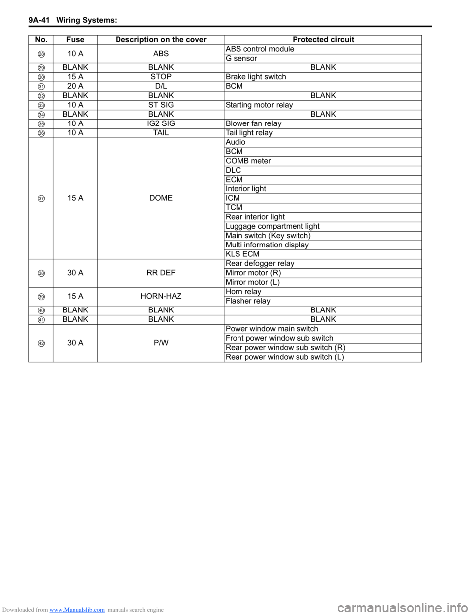
10 A ABSABS control module
G sensor
BLANK BLANK BLANK
15 A STOP Brake light switch
20 A D/L BCM
BLANK BLANK BLANK
10 A ST SIG Starting motor relay
BLANK BLANK BLANK
10 A IG2 SIG Blower fan relay
10 A TAIL Tail light relay
15 A DOMEAudio
BCM
COMB meter
DLC
ECM
Interior light
ICM
TCM
Rear interior light
Luggage compartment light
Main switch (Key switch)
Multi information display
KLS ECM
30 A RR DEFRear defogger relay
Mirror motor (R)
Mirror motor (L)
15 A HORN-HAZHorn relay
Flasher relay
BLANK BLANK BLANK
BLANK BLANK BLANK
30 A P/WPower window main switch
Front power window sub switch
Rear power window sub switch (R)
Rear power window sub switch (L) No. Fuse Description on the cover Protected circuit
Page 1233 of 1556

Downloaded from www.Manualslib.com manuals search engine Wiring Systems: 9A-66
Weld spliceC311
CKP
sensor
3C31
51
PNKBLK/ORN
BLK/RED
12
GW
J/B
2
15ASTOP
30
15ADOME
37
E0120
GRN/WHT
GRN/WHT
GRN
E3234
E181
Brake
light
switch
1 2
ECM
2
CMP
sensor
C01 C01
BLK
BLK
BLK
3463
1529 3031
1C32
52C01 E0122302813
RED/YEL
BLK/ORNBLKBLKBLKBLK
BLK/REDBLK/RED
32
J/B
E3251
2
YG
YEL/GRNYEL/BLKWHT/REDWHTYEL/RED
Starting
motor
relayICM
"A-7"YBYR
BR
2
W"A-1"
Starting
motor
relay
"A-1"
VSS
"A-6"
C343
E3711
I6RW0C910938-02