2006 SUZUKI SX4 stop start
[x] Cancel search: stop startPage 1237 of 1556
Downloaded from www.Manualslib.com manuals search engine Wiring Systems: 9A-70
Weld spliceC311
GW
J/B
2
15ASTOP
30
15ADOME
37
E0120
GRN/WHT
GRN/WHT
GRN
E3234
E181
Brake
light
switch
1 2
ECM
2
CMP
sensor
C01
BLK
36
1531 30
1or3C32
20C01 E0148302813
RED/YEL
BLK/ORNBLK/ORN
BLK/ORN
BLKBLKBLK
C01 E0158
BLK/RED
3or2 2or1
J/B
E3251
2
YG
YEL/GRNYEL/BLKWHT/REDWHTYEL/RED
Starting
motor
relay Starting
motor
relay
"A-1"ICM
"A-7"YBYR
2
W"A-1"
CKP
sensor
3C31
21
PNKBLK/ORN
BLK/RED
12
Weld
splice
C313
I6RW0C910943-02
Page 1241 of 1556
Downloaded from www.Manualslib.com manuals search engine Wiring Systems: 9A-74
G333
E381S171
G346161514
GWGY
J/B
2
15ASTOP
30
15ADOME
37
E0120
GRN/WHT
GRN/WHT
GRN
12
10AIG1 SIG
26
LT GRN/BLK
8
GRN/YEL
622RED/WHTLT GRN21BLK/YEL
RED/WHT
RED/BLK
LT GRNBLK/YEL
RB
E325 E323 E325 E3234
15AIG COIL
20
5
E181
3 4Brake
light
switch
MAIN RESUME/
ACCEL SET/
COAST CANCEL
1 2
S61
12
Steering
switch
(Auto
cruise
switch)
Contact
coilContact
coil
11 610
121110
6
Cruise control (IF EQPD)
ECM
2
CMP
sensor
C01
BLK
34
1529 3031
3C32
52C01 E0122302813
RED/YEL
PNK/BLUBLKBLKBLKBLK
BLK/RED
12
J/B
E3251
2
"C-2"
G346
S171
YG
YEL/GRNYEL/BLKWHT/REDWHTYEL/RED
Starting
motor
relay Starting
motor
relay
"A-1"ICM
"A-7"YBYR
2
W"A-1"
E01
LT GRN/BLK
BLK
BLKBLK
7C019
CPP
cut
switch
E1921
2
79
BLK/ORNBLK/ORN
BLK/ORN
Current
sensor
C461
23
Weld
splice
C312
BLK/WHT
I6RW0C910946-04
Page 1471 of 1556
Downloaded from www.Manualslib.com manuals search engine Table of Contents 10- i
10
Section 10
CONTENTS
Control Systems
Precautions ............................................... 10-1
Precautions........................................................... 10-1
Precautions for Control Systems......................... 10-1
Body Electrical Control System ........... 10B-1
Precautions......................................................... 10B-1
Precautions in Diagnosing Trouble ................... 10B-1
General Description ........................................... 10B-1
BCM General Description ................................. 10B-1
CAN Communication System Description......... 10B-1
Theft Deterrent Light ......................................... 10B-2
Security Alarm Description (If Equipped) .......... 10B-2
Schematic and Routing Diagram ...................... 10B-3
Body Electrical Control System Wiring Circuit
Diagram .......................................................... 10B-3
Connector Layout Diagram of BCM and
Junction Block ................................................. 10B-6
Component Location ......................................... 10B-7
BCM and Related System Component
Location .......................................................... 10B-7
Diagnostic Information and Procedures .......... 10B-8
BCM Self-Diagnosis Function ........................... 10B-8
Body Electrical Control System Check.............. 10B-9
Scan Tool Data ............................................... 10B-11
DTC Table ....................................................... 10B-13
DTC Check ..................................................... 10B-14
DTC Clearance ............................................... 10B-15
BCM Power Circuit and Ground Circuit Check 10B-16
DTC B1133 (DTC No. 1133): Battery Voltage
Too High ....................................................... 10B-17
DTC B1141 / DTC B1142 (No. 1141 / No.
1142) Outside Air Temperature (Ambient
Temp.) Sensor Circuit Malfunction ................ 10B-18
DTC B1150 (No. 1150): Air Bag
Communication Circuit Malfunction .............. 10B-19
DTC B1157 (No. 1157) Air Bag Deployment
Signal Input ................................................... 10B-20
DTC B1170 (No. 1170): EEPROM Access
Error .............................................................. 10B-20
DTC U0073 (No. 0073): Control Module
Communication Bus Off ................................ 10B-20
DTC U0100 (No. 0100): Lost Communication
with ECM....................................................... 10B-20DTC U0101 (No. 0101): Lost Communication
with TCM ....................................................... 10B-20
DTC U0155 (No. 0155): Lost Communication
with Instrument Panel Cluster (IPC) Control
Module .......................................................... 10B-20
DTC U1144 (No. 1144): Lost Communication
with Keyless Start Control Module ................ 10B-20
Inspection of BCM and Its Circuits .................. 10B-21
Repair Instructions ..........................................10B-28
BCM (Included in Junction Block) Removal
and Installation .............................................. 10B-28
Security Alarm Mode Selection Procedure (If
Equipped) ...................................................... 10B-29
Outside Air Temperature Sensor Removal
and Installation .............................................. 10B-29
Outside Air Temperature Sensor Inspection ... 10B-29
Special Tools and Equipment .........................10B-29
Special Tool .................................................... 10B-29
Immobilizer Control System ................. 10C-1
Precautions.........................................................10C-1
Precautions in Diagnosing Troubles .................10C-1
Precaution in Replacing ECM ...........................10C-1
Precaution in Replacing Ignition Key ................10C-1
Precautions in Handling Immobilizer Control
System ............................................................10C-1
General Description ...........................................10C-2
Immobilizer Control System Introduction ..........10C-2
On-Board Diagnostic System Description
(Self-diagnosis Function)................................10C-2
Schematic and Routing Diagram ......................10C-3
Immobilizer Control System Wiring Circuit
Diagram...........................................................10C-3
Component Location .........................................10C-5
Immobilizer Control System Components
Location...........................................................10C-5
Diagnostic Information and Procedures ..........10C-5
Immobilizer Control System Check ...................10C-5
DTC Check........................................................10C-6
DTC Clearance .................................................10C-6
DTC Table .........................................................10C-7
Scan Tool Data .................................................10C-8
Immobilizer Indicator Light Does Not Come
ON with Ignition Switch ON and Engine Stop ..10C-9
Page 1476 of 1556
Downloaded from www.Manualslib.com manuals search engine 10B-3 Body Electrical Control System:
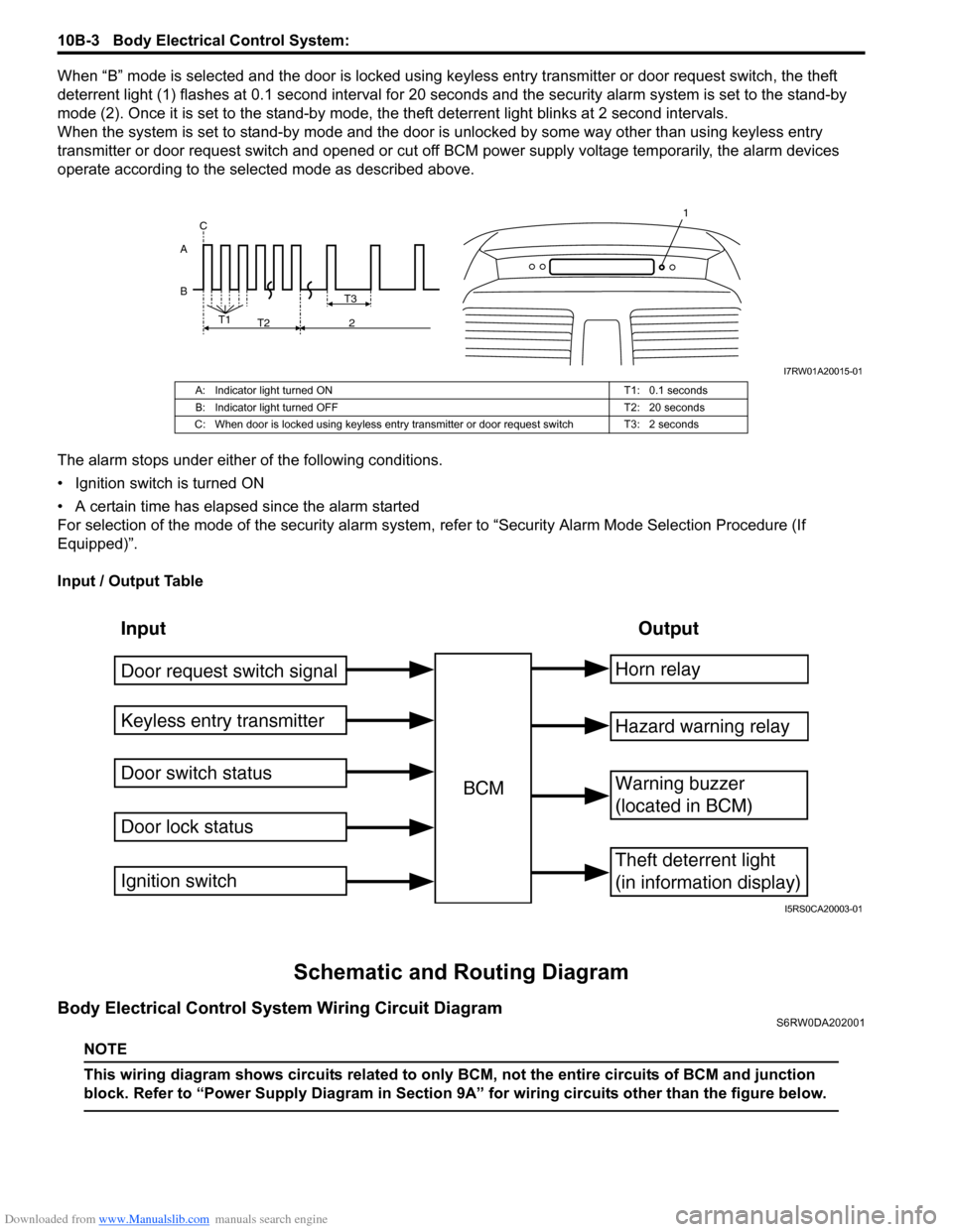
When “B” mode is selected and the door is locked using keyless entry transmitter or door request switch, the theft
deterrent light (1) flashes at 0.1 second interval for 20 seconds and the security alarm system is set to the stand-by
mode (2). Once it is set to the stand-by mode, the theft deterrent light blinks at 2 second intervals.
When the system is set to stand-by mode and the door is unlocked by some way other than using keyless entry
transmitter or door request switch and opened or cut off BCM power supply voltage temporarily, the alarm devices
operate according to the selected mode as described above.
The alarm stops under either of the following conditions.
• Ignition switch is turned ON
• A certain time has elapsed since the alarm started
For selection of the mode of the security alarm system, refer to “Security Alarm Mode Selection Procedure (If
Equipped)”.
Input / Output Table
Schematic and Routing Diagram
Body Electrical Control System Wiring Circuit DiagramS6RW0DA202001
NOTE
This wiring diagram shows circuits related to only BCM, not the entire circuits of BCM and junction
block. Refer to “Power Supply Diagram in Section 9A” for wiring circuits other than the figure below.
B AT3
T1
T2 2 C
1
I7RW01A20015-01
A: Indicator light turned ON T1: 0.1 seconds
B: Indicator light turned OFF T2: 20 seconds
C: When door is locked using keyless entry transmitter or door request switch T3: 2 seconds
Input Output
Keyless entry transmitter
Door switch status
Door lock statusBCMHorn relay
Theft deterrent light
(in information display)
Warning buzzer
(located in BCM)
Hazard warning relay
Door request switch signal
Ignition switch
I5RS0CA20003-01
Page 1488 of 1556
Downloaded from www.Manualslib.com manuals search engine 10B-15 Body Electrical Control System:
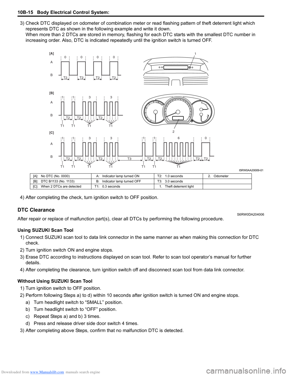
3) Check DTC displayed on odometer of combination meter or read flashing pattern of theft deterrent light which
represents DTC as shown in the following example and write it down.
When more than 2 DTCs are stored in memory, flashing for each DTC starts with the smallest DTC number in
increasing order. Also, DTC is indicated repeatedly until the ignition switch is turned OFF.
4) After completing the check, turn ignition switch to OFF position.
DTC ClearanceS6RW0DA204006
After repair or replace of malfunction part(s), clear all DTCs by performing the following procedure.
Using SUZUKI Scan Tool
1) Connect SUZUKI scan tool to data link connector in the same manner as when making this connection for DTC
check.
2) Turn ignition switch ON and engine stops.
3) Erase DTC according to instructions displayed on scan tool. Refer to scan tool operator’s manual for further
details.
4) After completing the clearance, turn ignition switch off and disconnect scan tool from data link connector.
Without Using SUZUKI Scan Tool
1) Turn ignition switch to OFF position.
2) Perform following Steps a) to d) within 10 seconds after ignition switch is turned ON and engine stops.
a) Turn headlight switch to “SMALL” position.
b) Turn headlight switch to “OFF” position.
c) Repeat Steps a) and b) 3 times.
d) Press and release driver side door switch 4 times.
3) After completing above Steps, confirm that no malfunction DTC is detected.
B A [B] [A]
[C]
B A B A
3 113
3 113 T2
T1 T1 T1T1
1
2
T2T2
T2
T1 T1 T1T1T2T2
0
T2
0
T2
0
T2
0
T2
11 6 0
T1 T1 T1
T2 T3T2T2T2
I5RW0AA20009-01
[A]: No DTC (No. 0000) A: Indicator lamp turned ON T2: 1.0 seconds 2. Odometer
[B]: DTC B1133 (No. 1133) B: Indicator lamp turned OFF T3: 3.0 seconds
[C]: When 2 DTCs are detected T1: 0.3 seconds 1. Theft deterrent light
Page 1504 of 1556
Downloaded from www.Manualslib.com manuals search engine 10C-2 Immobilizer Control System:
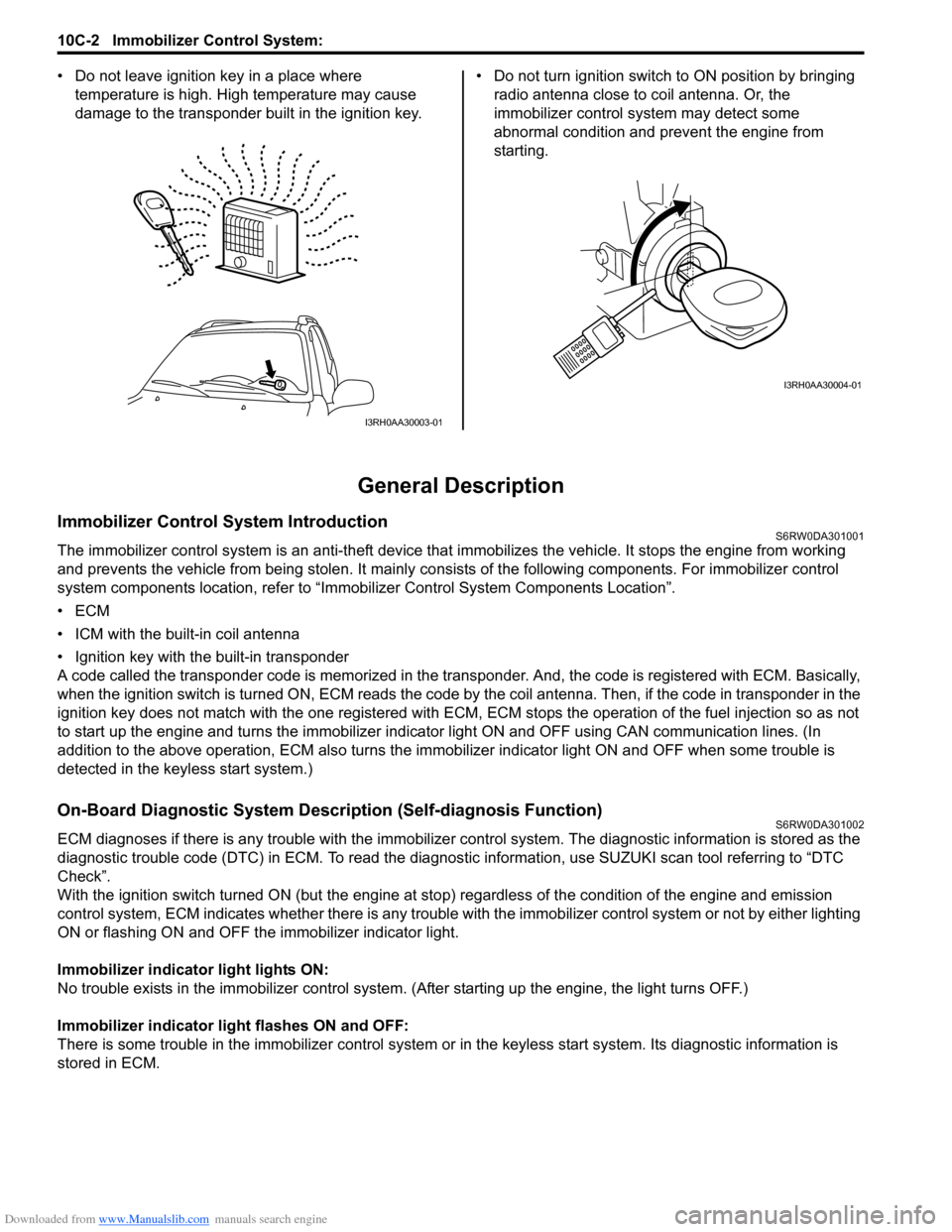
• Do not leave ignition key in a place where
temperature is high. High temperature may cause
damage to the transponder built in the ignition key.• Do not turn ignition switch to ON position by bringing
radio antenna close to coil antenna. Or, the
immobilizer control system may detect some
abnormal condition and prevent the engine from
starting.
General Description
Immobilizer Control System IntroductionS6RW0DA301001
The immobilizer control system is an anti-theft device that immobilizes the vehicle. It stops the engine from working
and prevents the vehicle from being stolen. It mainly consists of the following components. For immobilizer control
system components location, refer to “Immobilizer Control System Components Location”.
•ECM
• ICM with the built-in coil antenna
• Ignition key with the built-in transponder
A code called the transponder code is memorized in the transponder. And, the code is registered with ECM. Basically,
when the ignition switch is turned ON, ECM reads the code by the coil antenna. Then, if the code in transponder in the
ignition key does not match with the one registered with ECM, ECM stops the operation of the fuel injection so as not
to start up the engine and turns the immobilizer indicator light ON and OFF using CAN communication lines. (In
addition to the above operation, ECM also turns the immobilizer indicator light ON and OFF when some trouble is
detected in the keyless start system.)
On-Board Diagnostic System Description (Self-diagnosis Function)S6RW0DA301002
ECM diagnoses if there is any trouble with the immobilizer control system. The diagnostic information is stored as the
diagnostic trouble code (DTC) in ECM. To read the diagnostic information, use SUZUKI scan tool referring to “DTC
Check”.
With the ignition switch turned ON (but the engine at stop) regardless of the condition of the engine and emission
control system, ECM indicates whether there is any trouble with the immobilizer control system or not by either lighting
ON or flashing ON and OFF the immobilizer indicator light.
Immobilizer indicator light lights ON:
No trouble exists in the immobilizer control system. (After starting up the engine, the light turns OFF.)
Immobilizer indicator light flashes ON and OFF:
There is some trouble in the immobilizer control system or in the keyless start system. Its diagnostic information is
stored in ECM.
I3RH0AA30003-01
I3RH0AA30004-01
Page 1507 of 1556
Downloaded from www.Manualslib.com manuals search engine Immobilizer Control System: 10C-5
Component Location
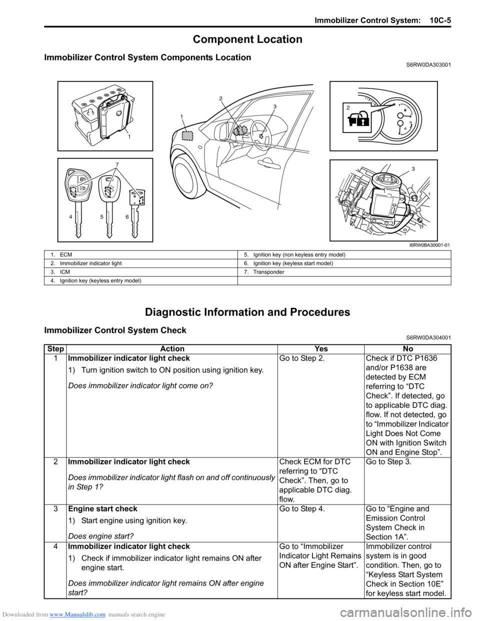
Immobilizer Control System Components LocationS6RW0DA303001
Diagnostic Information and Procedures
Immobilizer Control System CheckS6RW0DA304001
3
4567
1
2
2
13
I6RW0BA30001-01
1. ECM 5. Ignition key (non keyless entry model)
2. Immobilizer indicator light 6. Ignition key (keyless start model)
3. ICM 7. Transponder
4. Ignition key (keyless entry model)
Step Action Yes No
1Immobilizer indicator light check
1) Turn ignition switch to ON position using ignition key.
Does immobilizer indicator light come on?Go to Step 2. Check if DTC P1636
and/or P1638 are
detected by ECM
referring to “DTC
Check”. If detected, go
to applicable DTC diag.
flow. If not detected, go
to “Immobilizer Indicator
Light Does Not Come
ON with Ignition Switch
ON and Engine Stop”.
2Immobilizer indicator light check
Does immobilizer indicator light flash on and off continuously
in Step 1?Check ECM for DTC
referring to “DTC
Check”. Then, go to
applicable DTC diag.
flow.Go to Step 3.
3Engine start check
1) Start engine using ignition key.
Does engine start?Go to Step 4. Go to “Engine and
Emission Control
System Check in
Section 1A”.
4Immobilizer indicator light check
1) Check if immobilizer indicator light remains ON after
engine start.
Does immobilizer indicator light remains ON after engine
start?Go to “Immobilizer
Indicator Light Remains
ON after Engine Start”.Immobilizer control
system is in good
condition. Then, go to
“Keyless Start System
Check in Section 10E”
for keyless start model.
Page 1511 of 1556
Downloaded from www.Manualslib.com manuals search engine Immobilizer Control System: 10C-9
Immobilizer Indicator Light Does Not Come ON with Ignition Switch ON and Engine StopS6RW0DA304006
Wiring Diagram
Refer to “Immobilizer Control System Wiring Circuit Diagram”.
Circuit Description
When the ignition switch is turned ON, ECM transmits the indication ON signal to the combination meter to turn ON the
immobilizer indicator light in case that there is not any problem with the immobilizer control system. Then, the
combination meter turns ON the light. When the engine is started up, ECM transmits the indication OFF signal to the
combination meter to turn OFF the light. Then, the combination meter turns OFF the immobilizer indicator light.
However, in case that there is some trouble with the immobilizer control system, the immobilizer indicator light flashes
ON and OFF when the ignition switch is turned ON.
Troubleshooting
Step Action Yes No
1Immobilizer indicator light power supply check
1) Turn the ignition switch to ON position.
Do other warning lights come ON?Go to Step 2. Go to Step 4.
2DTC check of ECM
1) Check ECM for DTC referring to “DTC Check in Section
1A”.
Is DTC U0073, U0101, U0121 and/or U0140 detected?Go to applicable DTC
diag. flow.Go to Step 3.
3DTC check of BCM
1) Check BCM for DTC referring to “DTC Check in Section
10B”.
Is DTC U0073, U0100, U0101, U0155 and/or U1144
detected?Go to applicable DTC
diag. flow.Substitute a known-
good combination meter
and recheck. If
immobilizer indicator
light still remains OFF,
substitute a known-
good ECM and recheck.
4Fuse check
1) Turn the ignition switch to OFF position.
2) Check fuse for combination meter circuit.
Is fuse blown?Replace blown fuse,
and then check for
short.Go to Step 5.
5Combination meter power supply wire circuit check
1) Remove combination meter referring to “Combination
Meter Removal and Installation in Section 9C”.
2) Check for proper connection at terminals and wires of
combination meter connector.
3) If OK, turn the ignition switch to ON position and
measure voltage between power supply terminal of
combination meter and vehicle body ground. Refer to
“Combination Meter Circuit Diagram in Section 9C”.
Is it 10 – 14 V?Go to Step 6. Repair open in power
supply wire circuit.
6Combination meter ground wire circuit check
1) Turn ignition switch OFF position.
2) Measure resistance between ground terminal of
combination meter connector and vehicle body ground.
Refer to “Combination Meter Circuit Diagram in Section
9C”.
Is resistance 1
Ω or less?Substitute a known-
good combination meter
and recheck. If still
remains OFF, substitute
a known-good ECM and
recheck.Repair open or high
resistance in ground
circuit.