2006 SUZUKI SX4 parking brake
[x] Cancel search: parking brakePage 1449 of 1556
Downloaded from www.Manualslib.com manuals search engine Body Structure: 9K-5
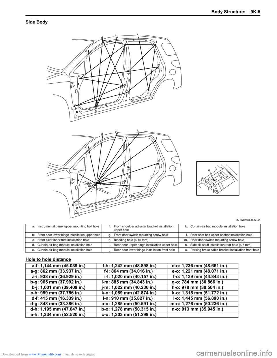
Side Body
Hole to hole distance
o
dek
fl
im
n
g
j
h
o
ac
b
dek
fl
im
n
g
j
h
ac
b
I5RW0A9B0005-02
a. Instrumental panel upper mounting bolt hole f. Front shoulder adjuster bracket installation
upper holek. Curtain-air bag module installation hole
b. Front door lower hinge installation upper hole g. Front door switch mounting screw hole l. Rear seat belt upper anchor installation hole
c. Front pillar inner trim installation hole h. Bleeding hole (φ 15 mm) m. Rear door switch mounting screw hole
d. Curtain-air bag module installation hole i. Rear door upper hinge installation upper hole n. Side sill scuff installation rear hole (φ 7 mm)
e. Curtain-air bag module installation hole j. Rear door lower hinge installation front hole o. Parking brake cable bracket installation front hole
a-f: 1,144 mm (45.039 in.) f-h: 1,242 mm (48.898 in.) d-o: 1,236 mm (48.661 in.)
a-g: 862 mm (33.937 in.) f-l: 864 mm (34.016 in.) e-o: 1,221 mm (48.071 in.)
a-i: 938 mm (36.929 in.) i-l: 1,020 mm (40.157 in.) f-o: 1,139 mm (44.843 in.)
b-g: 965 mm (37.992 in.) i-m: 885 mm (34.843 in.) g-o: 784 mm (30.866 in.)
b-j: 1,001 mm (39.409 in.) j-m: 1,022 mm (40.236 in.) h-o: 978 mm (38.504 in.)
c-h: 959 mm (37.756 in.) k-n: 1,089 mm (42.874 in.) k-o: 1,315 mm (51.772 in.)
d-f: 415 mm (16.339 in.) l-n: 910 mm (35.827 in.) l-o: 1,445 mm (56.890 in.)
d-g: 848 mm (33.386 in.) a-o: 1,285 mm (50.591 in.) m-o: 1,276 mm (50.236 in.)
d-h: 1,195 mm (47.047 in.) b-o: 1,278 mm (50.315 in.) n-o: 913 mm (35.945 in.)
e-h: 1,334 mm (52.520 in.) c-o: 1,303 mm (51.299 in.)
Page 1450 of 1556
Downloaded from www.Manualslib.com manuals search engine 9K-6 Body Structure:
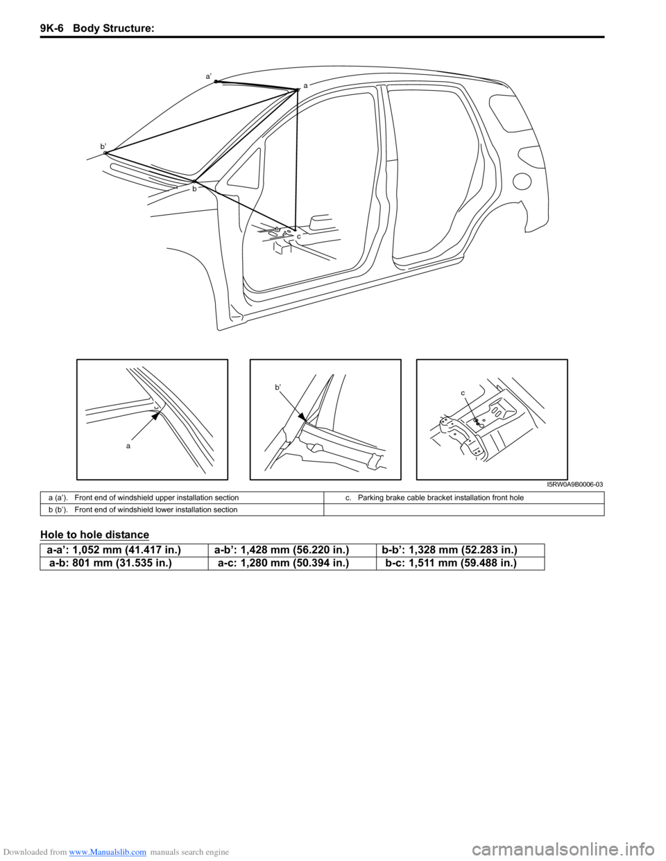
Hole to hole distance
c
a
a’a
b b’
c
b’
I5RW0A9B0006-03
a (a’). Front end of windshield upper installation section c. Parking brake cable bracket installation front hole
b (b’). Front end of windshield lower installation section
a-a’: 1,052 mm (41.417 in.) a-b’: 1,428 mm (56.220 in.) b-b’: 1,328 mm (52.283 in.)
a-b: 801 mm (31.535 in.) a-c: 1,280 mm (50.394 in.) b-c: 1,511 mm (59.488 in.)
Page 1474 of 1556
Downloaded from www.Manualslib.com manuals search engine 10B-1 Body Electrical Control System:
Control Systems
Body Electrical Control System
Precautions
Precautions in Diagnosing TroubleS6RW0DA200001
• Diagnostic information stored in BCM memory can be cleared as well as checked by using SUZUKI scan tool.
Before using scan tool, read its Operator’s (Instruction) Manual carefully to have good understanding as to what
functions are available and how to use it.
• Be sure to read “Precautions for Electrical Circuit Service in Section 00” before inspection and observe what is
written there.
• Communication of ECM, TCM (A/T model), ABS control module, 4WD control module (if equipped), keyless start
control module (if equipped), combination meter and BCM is established by CAN (Controller Area Network). For
detail of CAN communication for BCM, refer to “CAN Communication System Description”. Therefore, handle CAN
communication line with care referring to “Precaution for CAN Communication System in Section 00”.
General Description
BCM General DescriptionS6RW0DA201001
The Body electrical Control Module (BCM) is
incorporated in junction block. Do not attempt removal of
BCM from junction block as it may cause contact failure.
The BCM incorporates relays and controllers which are
used for the following systems and controls them.
• Power door lock (if equipped)
• Keyless entry (if equipped)
• Door lock function of keyless start system (if
equipped)
• Rear wiper
• Combination meter
• Interior light• Warning buzzer
• Rear end door window defogger and door mirror
heater (if equipped)
• Rear end door opener (if equipped)
• Theft deterrent light
Also, the BCM has a function to cause the interior light
and open door warning light in the combination meter to
turn off when any door is left open for longer than 15
minutes to reduce wasteful battery consumption.
In addition, it is possible to check operation of actuator
which is controlled by BCM by using the output test
function of SUZUKI scan tool to operate actuator
simulatively.
CAN Communication System DescriptionS6RW0DA201002
Refer to “CAN Communication System Description in Section 1A” for CAN communication system description.
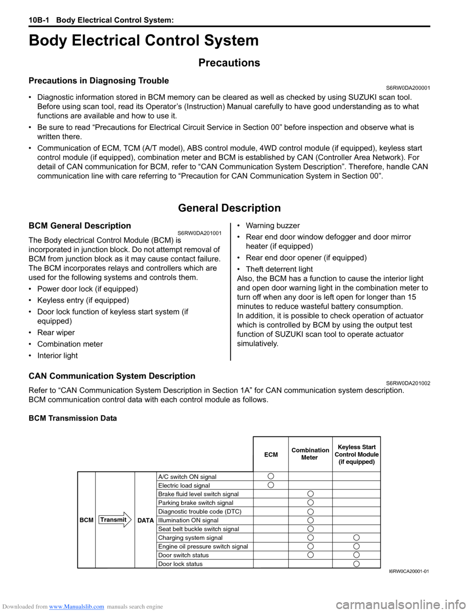
BCM communication control data with each control module as follows.
BCM Transmission Data
A/C switch ON signal
Electric load signal
Brake fluid level switch signal
Parking brake switch signal
Diagnostic trouble code (DTC)
Illumination ON signal
Seat belt buckle switch signal
Charging system signal
Engine oil pressure switch signal
Door switch status
Door lock statusECMKeyless Start
Control Module
(if equipped) Combination
Meter
BCMTransmit
DATA
I6RW0CA20001-01
Page 1478 of 1556
Downloaded from www.Manualslib.com manuals search engine 10B-5 Body Electrical Control System:
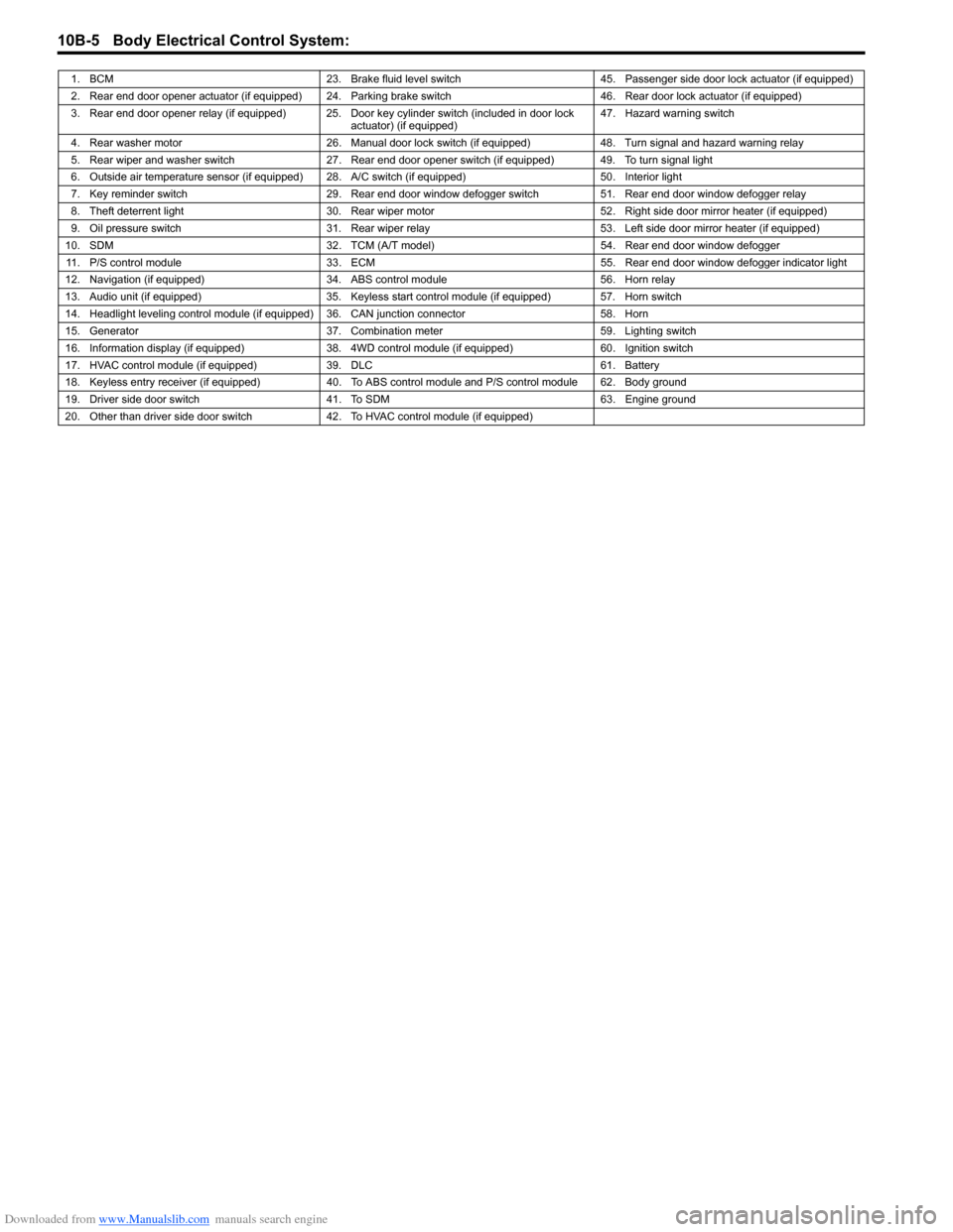
1. BCM 23. Brake fluid level switch 45. Passenger side door lock actuator (if equipped)
2. Rear end door opener actuator (if equipped) 24. Parking brake switch 46. Rear door lock actuator (if equipped)
3. Rear end door opener relay (if equipped) 25. Door key cylinder switch (included in door lock
actuator) (if equipped)47. Hazard warning switch
4. Rear washer motor 26. Manual door lock switch (if equipped) 48. Turn signal and hazard warning relay
5. Rear wiper and washer switch 27. Rear end door opener switch (if equipped) 49. To turn signal light
6. Outside air temperature sensor (if equipped) 28. A/C switch (if equipped) 50. Interior light
7. Key reminder switch 29. Rear end door window defogger switch 51. Rear end door window defogger relay
8. Theft deterrent light 30. Rear wiper motor 52. Right side door mirror heater (if equipped)
9. Oil pressure switch 31. Rear wiper relay 53. Left side door mirror heater (if equipped)
10. SDM 32. TCM (A/T model) 54. Rear end door window defogger
11. P/S control module 33. ECM 55. Rear end door window defogger indicator light
12. Navigation (if equipped) 34. ABS control module 56. Horn relay
13. Audio unit (if equipped) 35. Keyless start control module (if equipped) 57. Horn switch
14. Headlight leveling control module (if equipped) 36. CAN junction connector 58. Horn
15. Generator 37. Combination meter 59. Lighting switch
16. Information display (if equipped) 38. 4WD control module (if equipped) 60. Ignition switch
17. HVAC control module (if equipped) 39. DLC 61. Battery
18. Keyless entry receiver (if equipped) 40. To ABS control module and P/S control module 62. Body ground
19. Driver side door switch 41. To SDM 63. Engine ground
20. Other than driver side door switch 42. To HVAC control module (if equipped)
Page 1480 of 1556
Downloaded from www.Manualslib.com manuals search engine 10B-7 Body Electrical Control System:
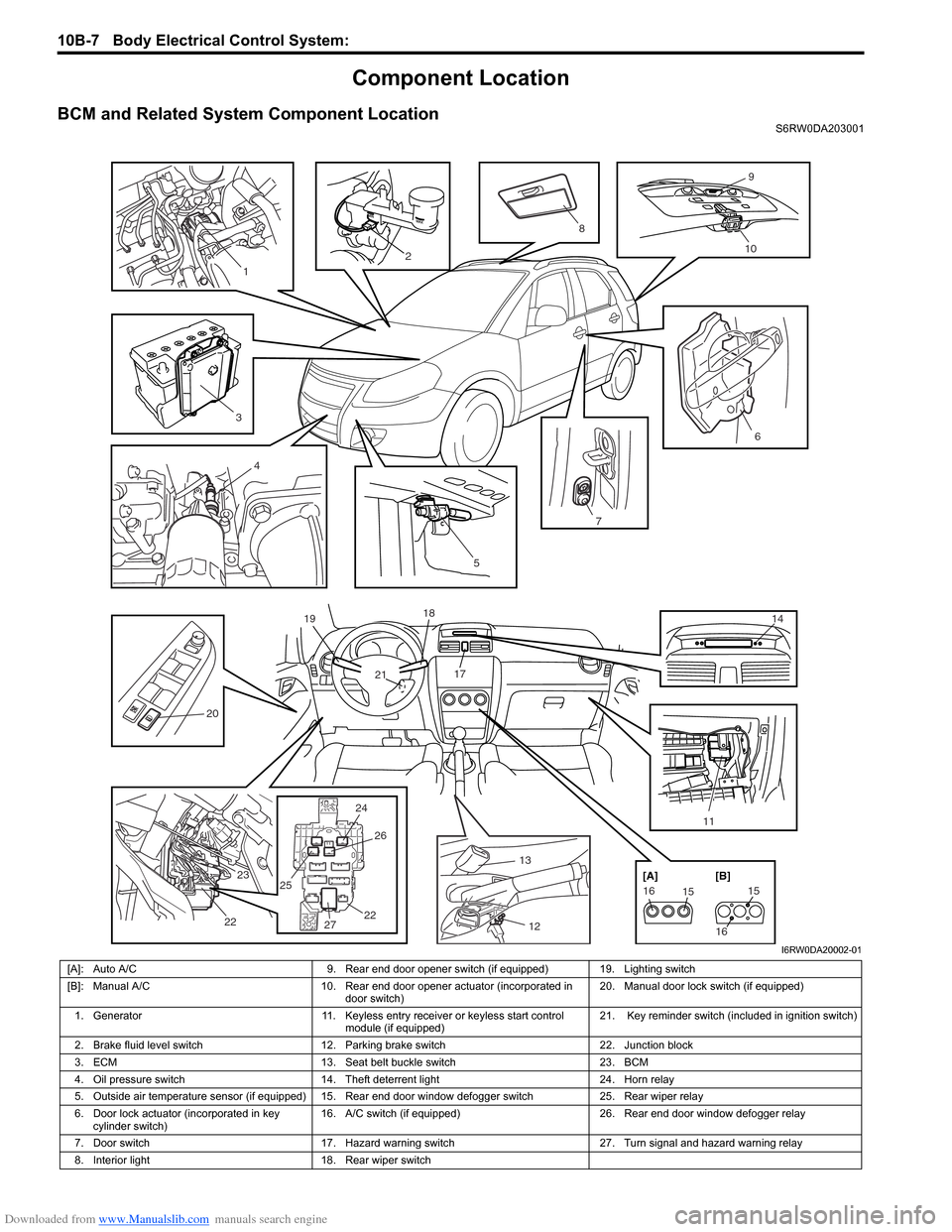
Component Location
BCM and Related System Component LocationS6RW0DA203001
13
12 17 18
21 19
14
24 25
2526
2722 23
22
2476
20
11
5
151615
16 [A] [B]
2
9
10
3
8
4
1
I6RW0DA20002-01
[A]: Auto A/C 9. Rear end door opener switch (if equipped) 19. Lighting switch
[B]: Manual A/C 10. Rear end door opener actuator (incorporated in
door switch)20. Manual door lock switch (if equipped)
1. Generator 11. Keyless entry receiver or keyless start control
module (if equipped)21. Key reminder switch (included in ignition switch)
2. Brake fluid level switch 12. Parking brake switch 22. Junction block
3. ECM 13. Seat belt buckle switch 23. BCM
4. Oil pressure switch 14. Theft deterrent light 24. Horn relay
5. Outside air temperature sensor (if equipped) 15. Rear end door window defogger switch 25. Rear wiper relay
6. Door lock actuator (incorporated in key
cylinder switch)16. A/C switch (if equipped) 26. Rear end door window defogger relay
7. Door switch 17. Hazard warning switch 27. Turn signal and hazard warning relay
8. Interior light 18. Rear wiper switch
Page 1481 of 1556
Downloaded from www.Manualslib.com manuals search engine Body Electrical Control System: 10B-8
Diagnostic Information and Procedures
BCM Self-Diagnosis FunctionS6RW0DA204001
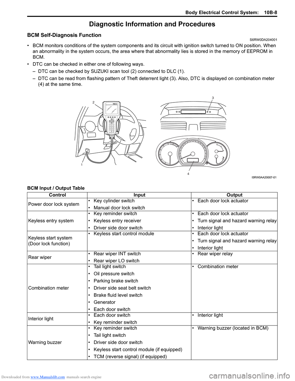
• BCM monitors conditions of the system components and its circuit with ignition switch turned to ON position. When
an abnormality in the system occurs, the area where that abnormality lies is stored in the memory of EEPROM in
BCM.
• DTC can be checked in either one of following ways.
– DTC can be checked by SUZUKI scan tool (2) connected to DLC (1).
– DTC can be read from flashing pattern of Theft deterrent light (3). Also, DTC is displayed on combination meter
(4) at the same time.
BCM Input / Output Table
3
4
2
1
I5RW0AA20007-01
Control Input Output
Power door lock system• Key cylinder switch
• Manual door lock switch• Each door lock actuator
Keyless entry system• Key reminder switch
• Keyless entry receiver
• Driver side door switch• Each door lock actuator
• Turn signal and hazard warning relay
• Interior light
Keyless start system
(Door lock function)• Keyless start control module • Each door lock actuator
• Turn signal and hazard warning relay
• Interior light
Rear wiper • Rear wiper INT switch
• Rear wiper LO switch• Rear wiper relay
Combination meter• Tail light switch
• Oil pressure switch
• Parking brake switch
• Driver side seat belt switch
• Brake fluid level switch
• Generator
• Each door switch• Combination meter
Interior light• Each door switch
• Key reminder switch• Interior light
Warning buzzer• Key reminder switch
• Tail light switch
• Driver side door switch
• Keyless start control module (if equipped)
• TCM (reverse signal) (if equipped)• Warning buzzer (located in BCM)
Page 1484 of 1556
Downloaded from www.Manualslib.com manuals search engine 10B-11 Body Electrical Control System:
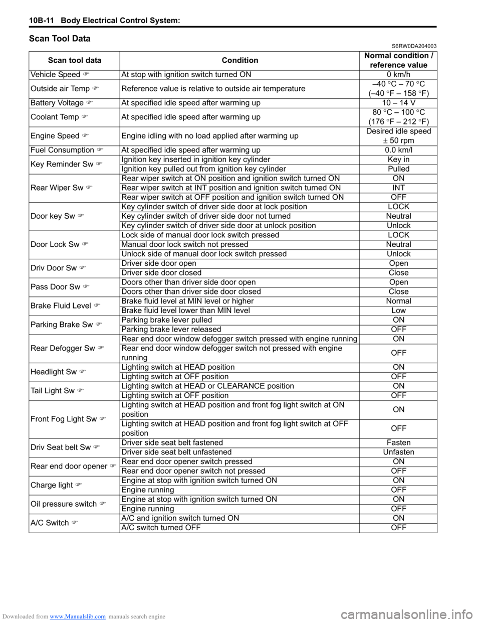
Scan Tool DataS6RW0DA204003
Scan tool data ConditionNormal condition /
reference value
Vehicle Speed �)At stop with ignition switch turned ON 0 km/h
Outside air Temp �)Reference value is relative to outside air temperature–40 °C – 70 °C
(–40 °F – 158 °F)
Battery Voltage �)At specified idle speed after warming up 10 – 14 V
Coolant Temp �)At specified idle speed after warming up80 °C – 100 °C
(176 °F – 212 °F)
Engine Speed �)Engine idling with no load applied after warming upDesired idle speed
± 50 rpm
Fuel Consumption �)At specified idle speed after warming up 0.0 km/l
Key Reminder Sw �)Ignition key inserted in ignition key cylinder Key in
Ignition key pulled out from ignition key cylinder Pulled
Rear Wiper Sw �)Rear wiper switch at ON position and ignition switch turned ON ON
Rear wiper switch at INT position and ignition switch turned ON INT
Rear wiper switch at OFF position and ignition switch turned ON OFF
Door key Sw �)Key cylinder switch of driver side door at lock position LOCK
Key cylinder switch of driver side door not turned Neutral
Key cylinder switch of driver side door at unlock position Unlock
Door Lock Sw �)Lock side of manual door lock switch pressed LOCK
Manual door lock switch not pressed Neutral
Unlock side of manual door lock switch pressed Unlock
Driv Door Sw �)Driver side door open Open
Driver side door closed Close
Pass Door Sw �)Doors other than driver side door open Open
Doors other than driver side door closed Close
Brake Fluid Level �)Brake fluid level at MIN level or higher Normal
Brake fluid level lower than MIN level Low
Parking Brake Sw �)Parking brake lever pulled ON
Parking brake lever released OFF
Rear Defogger Sw �)Rear end door window defogger switch pressed with engine running ON
Rear end door window defogger switch not pressed with engine
runningOFF
Headlight Sw �)Lighting switch at HEAD position ON
Lighting switch at OFF position OFF
Tail Light Sw �)Lighting switch at HEAD or CLEARANCE position ON
Lighting switch at OFF position OFF
Front Fog Light Sw �)Lighting switch at HEAD position and front fog light switch at ON
positionON
Lighting switch at HEAD position and front fog light switch at OFF
positionOFF
Driv Seat belt Sw
�)Driver side seat belt fastened Fasten
Driver side seat belt unfastened Unfasten
Rear end door opener �)Rear end door opener switch pressed ON
Rear end door opener switch not pressed OFF
Charge light �)Engine at stop with ignition switch turned ON ON
Engine running OFF
Oil pressure switch �)Engine at stop with ignition switch turned ON ON
Engine running OFF
A/C Switch �)A/C and ignition switch turned ON ON
A/C switch turned OFF OFF
Page 1485 of 1556
Downloaded from www.Manualslib.com manuals search engine Body Electrical Control System: 10B-12
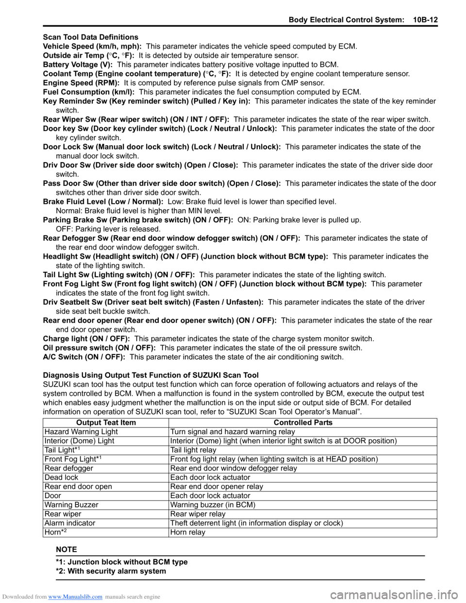
Scan Tool Data Definitions
Vehicle Speed (km/h, mph): This parameter indicates the vehicle speed computed by ECM.
Outside air Temp (°C, °F): It is detected by outside air temperature sensor.
Battery Voltage (V): This parameter indicates battery positive voltage inputted to BCM.
Coolant Temp (Engine coolant temperature) (°C, °F): It is detected by engine coolant temperature sensor.
Engine Speed (RPM): It is computed by reference pulse signals from CMP sensor.
Fuel Consumption (km/l): This parameter indicates the fuel consumption computed by ECM.
Key Reminder Sw (Key reminder switch) (Pulled / Key in): This parameter indicates the state of the key reminder
switch.
Rear Wiper Sw (Rear wiper switch) (ON / INT / OFF): This parameter indicates the state of the rear wiper switch.
Door key Sw (Door key cylinder switch) (Lock / Neutral / Unlock): This parameter indicates the state of the door
key cylinder switch.
Door Lock Sw (Manual door lock switch) (Lock / Neutral / Unlock): This parameter indicates the state of the
manual door lock switch.
Driv Door Sw (Driver side door switch) (Open / Close): This parameter indicates the state of the driver side door
switch.
Pass Door Sw (Other than driver side door switch) (Open / Close): This parameter indicates the state of the door
switches other than driver side door switch.
Brake Fluid Level (Low / Normal): Low: Brake fluid level is lower than specified level.
Normal: Brake fluid level is higher than MIN level.
Parking Brake Sw (Parking brake switch) (ON / OFF): ON: Parking brake lever is pulled up.
OFF: Parking lever is released.
Rear Defogger Sw (Rear end door window defogger switch) (ON / OFF): This parameter indicates the state of
the rear end door window defogger switch.
Headlight Sw (Headlight switch) (ON / OFF) (Junction block without BCM type): This parameter indicates the
state of the lighting switch.
Tail Light Sw (Lighting switch) (ON / OFF): This parameter indicates the state of the lighting switch.
Front Fog Light Sw (Front fog light switch) (ON / OFF) (Junction block without BCM type): This parameter
indicates the state of the front fog light switch.
Driv Seatbelt Sw (Driver seat belt switch) (Fasten / Unfasten): This parameter indicates the state of the driver
side seat belt buckle switch.
Rear end door opener (Rear end door opener switch) (ON / OFF): This parameter indicates the state of the rear
end door opener switch.
Charge light (ON / OFF): This parameter indicates the state of the charge system monitor switch.
Oil pressure switch (ON / OFF): This parameter indicates the state of the oil pressure switch.
A/C Switch (ON / OFF): This parameter indicates the state of the air conditioning switch.
Diagnosis Using Output Test Function of SUZUKI Scan Tool
SUZUKI scan tool has the output test function which can force operation of following actuators and relays of the
system controlled by BCM. When a malfunction is found in the system controlled by BCM, execute the output test
which enables easy judgment whether the malfunction is on the input side or output side of BCM. For detailed
information on operation of SUZUKI scan tool, refer to “SUZUKI Scan Tool Operator’s Manual”.
NOTE
*1: Junction block without BCM type
*2: With security alarm system
Output Teat Item Controlled Parts
Hazard Warning Light Turn signal and hazard warning relay
Interior (Dome) Light Interior (Dome) light (when interior light switch is at DOOR position)
Tail Light*
1Tail light relay
Front Fog Light*1Front fog light relay (when lighting switch is at HEAD position)
Rear defogger Rear end door window defogger relay
Dead lock Each door lock actuator
Rear end door open Rear end door opener relay
Door Each door lock actuator
Warning Buzzer Warning buzzer (in BCM)
Rear wiper Rear wiper relay
Alarm indicator Theft deterrent light (in information display or clock)
Horn*
2Horn relay