Page 1494 of 1556

Downloaded from www.Manualslib.com manuals search engine 10B-21 Body Electrical Control System:
Inspection of BCM and Its CircuitsS6RW0DA204017
BCM and its circuits can be checked at BCM wiring couplers by measuring voltage and resistance.
CAUTION!
BCM cannot be checked by itself. It is strictly prohibited to connect voltmeter or ohmmeter to BCM
with couplers disconnected from it.
Voltage Check
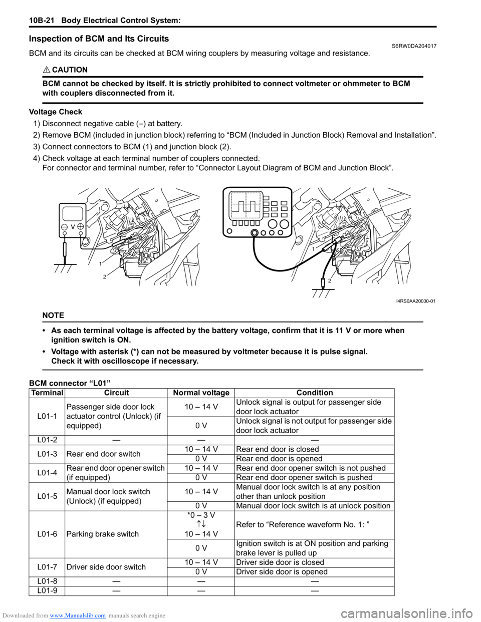
1) Disconnect negative cable (–) at battery.
2) Remove BCM (included in junction block) referring to “BCM (Included in Junction Block) Removal and Installation”.
3) Connect connectors to BCM (1) and junction block (2).
4) Check voltage at each terminal number of couplers connected.
For connector and terminal number, refer to “Connector Layout Diagram of BCM and Junction Block”.
NOTE
• As each terminal voltage is affected by the battery voltage, confirm that it is 11 V or more when
ignition switch is ON.
• Voltage with asterisk (*) can not be measured by voltmeter because it is pulse signal.
Check it with oscilloscope if necessary.
BCM connector “L01”
1
2
1
2
I4RS0AA20030-01
Terminal Circuit Normal voltage Condition
L01-1Passenger side door lock
actuator control (Unlock) (if
equipped)10 – 14 VUnlock signal is output for passenger side
door lock actuator
0 VUnlock signal is not output for passenger side
door lock actuator
L01-2 — — —
L01-3 Rear end door switch10 – 14 V Rear end door is closed
0 V Rear end door is opened
L01-4Rear end door opener switch
(if equipped)10 – 14 V Rear end door opener switch is not pushed
0 V Rear end door opener switch is pushed
L01-5Manual door lock switch
(Unlock) (if equipped)10 – 14 VManual door lock switch is at any position
other than unlock position
0 V Manual door lock switch is at unlock position
L01-6 Parking brake switch*0 – 3 V
↑↓
10 – 14 VRefer to “Reference waveform No. 1: ”
0 VIgnition switch is at ON position and parking
brake lever is pulled up
L01-7 Driver side door switch10 – 14 V Driver side door is closed
0 V Driver side door is opened
L01-8 — — —
L01-9 — — —
Page 1495 of 1556

Downloaded from www.Manualslib.com manuals search engine Body Electrical Control System: 10B-22
BCM connector “E04”L01-10Driver side door lock
actuator control (Unlock) (if
equipped)10 – 14 VUnlock signal is output for driver side door
lock actuator
0 VUnlock signal is not output for driver side
door lock actuator
L01-11Rear end door opener
actuator control (if equipped)0 VRear end door actuator motor is not in
operation
10 – 14 V Rear end door actuator motor is in operation
L01-12Manual door lock switch
(Lock) (if equipped)10 – 14 VManual door lock switch is at any position
other than lock position
0 V Manual door lock switch is at lock position
L01-13 — — —
L01-14 Driver side seat belt switch*0 – 3 V
↑↓
10 – 14 VRefer to “Reference waveform No. 2: ”
0 VIgnition switch is at ON position and driver
side seat belt is unfastened
L01-15Door switch (other than
driver side door and rear end
door)10 – 14 VRear right and left side door and passenger
side door are closed
0 VAny one of the door is opened (except driver
side door and rear end door)
L01-16Driver side door key cylinder
switch (Lock) (if equipped)10 – 14 VDriver side door key cylinder switch is at any
position other than lock position
0 VDriver side door key cylinder switch is at lock
position
L01-17Driver side door key cylinder
switch (Unlock) (if equipped)10 – 14 VDriver side door key cylinder switch is at any
position other than unlock position
0 VDriver side door key cylinder switch is at
unlock position
L01-18 — — —
Terminal Circuit Normal voltage Condition
E04-1CAN communication line (high)
for ABS control module*2.5 – 3.6 V
Refer to “Reference waveform No. 3: ”
E04-2CAN communication line (low)
for ABS control module*1.6 – 2.5 V
E04-3 — — —
E04-4 Generator “L” terminal10 – 14 V Engine is running
0 V Ignition switch is at ON position
E04-5 Brake fluid level switch*0 – 3 V
↑↓
10 – 14 VRefer to “Reference waveform No. 1: ”
0 VIgnition switch is at ON position, parking brake
lever is released and brake fluid level is lower
than MIN level
E04-6 — — —
E04-7 — — —
E04-8Sensor ground for outside air
temperature sensor (if
equipped)0 V —
E04-9Serial communication line of
data link connector for ABS
control module7 – 12 V Ignition switch is at ON position
E04-10Outside air temperature sensor
(if equipped)About 1.5 VIgnition switch is at ON position and outside
air temperature approx. 20 °C (68
°F)
E04-11 Oil pressure switch*3 – 14 V Refer to “Reference waveform No. 4: ”
0 VIgnition switch is at ON position and engine is
at stop
E04-12 — — — Terminal Circuit Normal voltage Condition
Page 1499 of 1556

Downloaded from www.Manualslib.com manuals search engine Body Electrical Control System: 10B-26
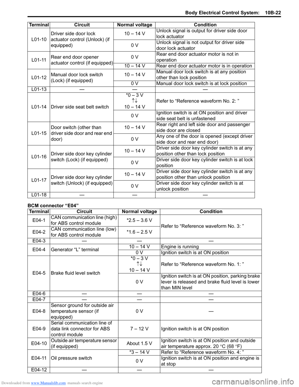
Reference waveform No. 1
Parking brake or brake fluid level switch signal (1)
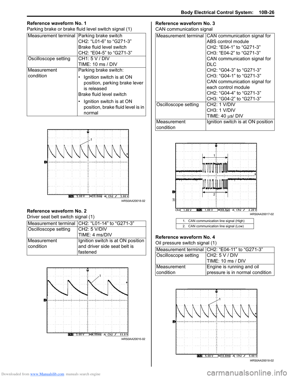
Reference waveform No. 2
Driver seat belt switch signal (1)Reference waveform No. 3
CAN communication signal
Reference waveform No. 4
Oil pressure switch signal (1) Measurement terminal Parking brake switch
CH2: “L01-6” to “G271-3”
Brake fluid level switch
CH2: “E04-5” to “G271-3”
Oscilloscope setting CH1: 5 V / DIV
TIME: 10 ms / DIV
Measurement
conditionParking brake switch:
• Ignition switch is at ON
position, parking brake lever
is released
Brake fluid level switch
• Ignition switch is at ON
position, brake fluid level is in
normal
Measurement terminal CH2: “L01-14” to “G271-3”
Oscilloscope setting CH2: 5 V/DIV
TIME: 4 ms/DIV
Measurement
conditionIgnition switch is at ON position
and driver side seat belt is
fastened
I4RS0AA20018-02
I4RS0AA20016-02
Measurement terminal CAN communication signal for
ABS control module
CH2: “E04-1” to “G271-3”
CH3: “E04-2” to “G271-3”
CAN communication signal for
DLC
CH2: “G04-3” to “G271-3”
CH3: “G04-1” to “G271-3”
CAN communication signal for
each control module
CH2: “G04-4” to “G271-3”
CH3: “G04-2” to “G271-3”
Oscilloscope setting CH2: 1 V/DIV
CH3: 1 V/DIV
TIME: 40 µs/ DIV
Measurement
conditionIgnition switch is at ON position
1. CAN communication line signal (High)
2. CAN communication line signal (Low)
Measurement terminal CH2: “E04-11” to “G271-3”
Oscilloscope setting CH2: 5 V / DIV
TIME: 10 ms / DIV
Measurement
conditionEngine is running and oil
pressure is in normal condition
I4RS0AA20017-02
I4RS0AA20018-02
Page 1549 of 1556

Downloaded from www.Manualslib.com manuals search engine Keyless Start System: 10E-27
Repair Instructions
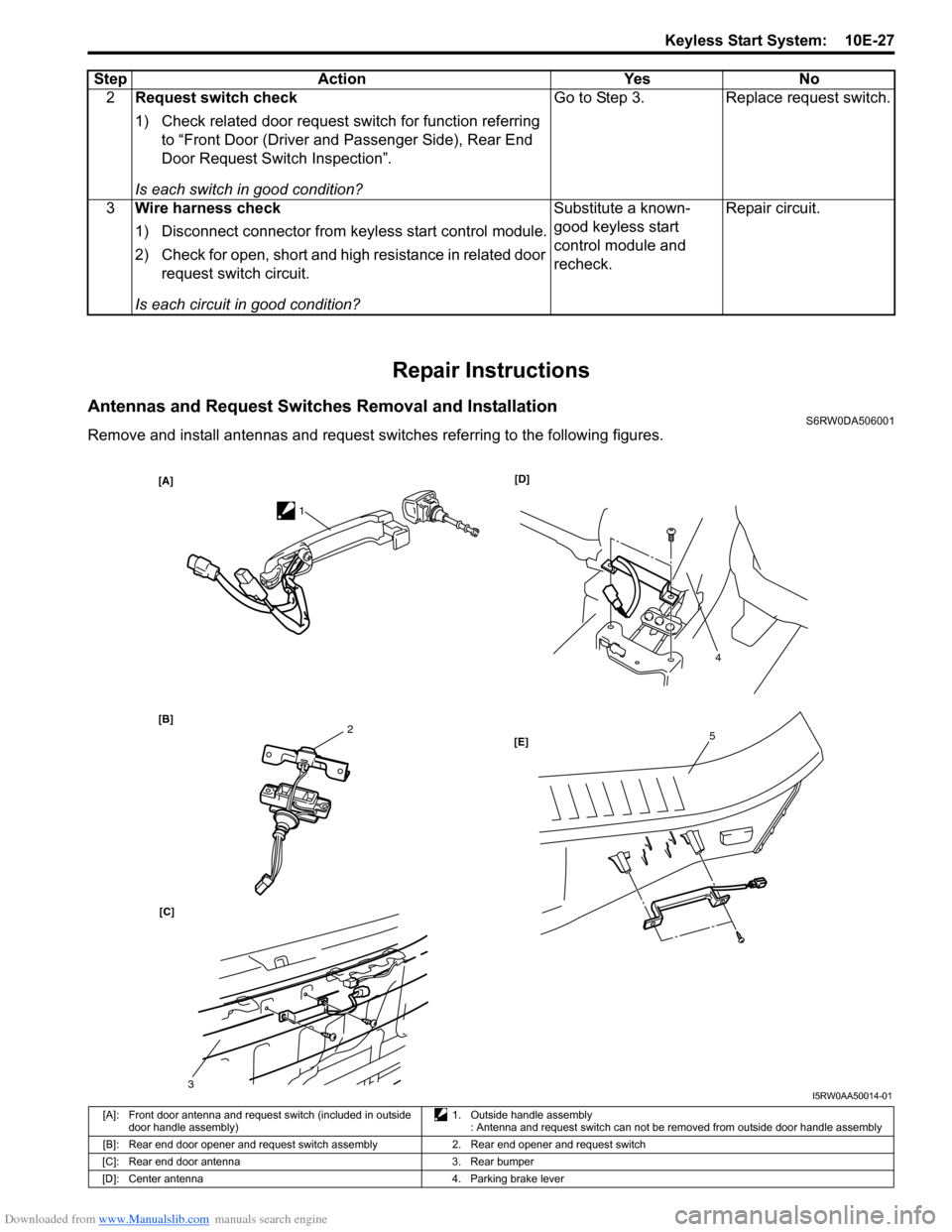
Antennas and Request Switches Removal and InstallationS6RW0DA506001
Remove and install antennas and request switches referring to the following figures.2Request switch check
1) Check related door request switch for function referring
to “Front Door (Driver and Passenger Side), Rear End
Door Request Switch Inspection”.
Is each switch in good condition?Go to Step 3. Replace request switch.
3Wire harness check
1) Disconnect connector from keyless start control module.
2) Check for open, short and high resistance in related door
request switch circuit.
Is each circuit in good condition?Substitute a known-
good keyless start
control module and
recheck.Repair circuit. Step Action Yes No
[A]
[B][D]
[C][E]
1
4
52
3I5RW0AA50014-01
[A]: Front door antenna and request switch (included in outside
door handle assembly)1. Outside handle assembly
: Antenna and request switch can not be removed from outside door handle assembly
[B]: Rear end door opener and request switch assembly 2. Rear end opener and request switch
[C]: Rear end door antenna 3. Rear bumper
[D]: Center antenna 4. Parking brake lever