Page 436 of 1556
Downloaded from www.Manualslib.com manuals search engine 2A-2 Suspension General Diagnosis:
NOTE
*1: Right-to-left trim height (“H”) difference should be within 15 mm (0.6 in.) with curb weight. (same
with rear side.)
Body leans or sways in
cornersLoose stabilizer barTighten stabilizer bar bolts or nuts, or replace
bushes.
Faulty strut (shock absorber) or
mountingReplace strut (shock absorber) or tighten
mounting.
Broken or sagging coil springsReplace coil springs.
OverloadedCheck loading.
Cupped tiresFront struts defectiveReplace struts.
Worn wheel bearingsReplace wheel bearings.
Excessive tire or wheel run-outReplace tire and/or wheel.
Worn ball jointsReplace suspension control arm.
Tire out of balanceAdjust tire balance. Condition Possible cause Correction / Reference Item
“H”
I2RH01210001-01
Page 440 of 1556

Downloaded from www.Manualslib.com manuals search engine 2B-3 Front Suspension:
Adjustment
1) Loosen right and left tie-rod end lock nuts (1) first.
2) Rotate right and left tie-rods (2) by the same amount
to align toe to specification. In this adjustment, the
lengths “A” of both right and left tie-rod should be
equal.
NOTE
Before rotating tie-rods (2), apply grease
between tie-rods and rack boots so that
boots won’t be twisted.
3) After adjustment, tighten lock nuts (1) to specified
torque.
Tightening torque
Tie-rod end lock nut (a): 45 N·m (4.5 kgf-m, 32.5
lb-ft)
NOTE
Make sure that rack boots are not twisted.
Steering Angle Check and Adjustment
When tie-rod or tie-rod end was replaced, check toe and
then also steering angle with turning radius gauge (1).
If steering angle is not correct, check whether right and
left tie-rods length “A” are equal.
NOTE
If tie-rod lengths were changed to adjust
steering angle, reinspect toe-in.
Steering angle
Inside: 36.0° ± 2°
Outside: 32.1° (Reference)
Reference Information
Side slip
When checked with side slip tester, side slip should
satisfy following specification.
Side slip
0 to IN 3.0 mm/m (0 to IN 0.118 in/3.3 ft)
If side slip is greatly difference, toe or front wheel
alignment may not be correct.
I3RH0A220002-01
I3RH0A220003-01
Page 442 of 1556

Downloaded from www.Manualslib.com manuals search engine 2B-5 Front Suspension:
Front Strut Assembly Removal and InstallationS6RW0D2206003
CAUTION!
When rebound stopper and strut assembly
were removed, check strut support lower nut
for specified torque before installing strut
assembly.
Removal
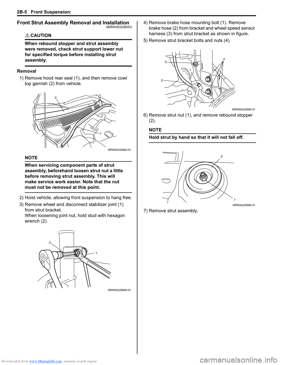
1) Remove hood rear seal (1), and then remove cowl
top garnish (2) from vehicle.
NOTE
When servicing component parts of strut
assembly, beforehand loosen strut nut a little
before removing strut assembly. This will
make service work easier. Note that the nut
must not be removed at this point.
2) Hoist vehicle, allowing front suspension to hang free.
3) Remove wheel and disconnect stabilizer joint (1)
from strut bracket.
When loosening joint nut, hold stud with hexagon
wrench (2).4) Remove brake hose mounting bolt (1). Remove
brake hose (2) from bracket and wheel speed sensor
harness (3) from strut bracket as shown in figure.
5) Remove strut bracket bolts and nuts (4).
6) Remove strut nut (1), and remove rebound stopper
(2).
NOTE
Hold strut by hand so that it will not fall off.
7) Remove strut assembly.
2
1
I5RW0A220003-01
1
2
I5RW0A220004-01
3
214
I5RW0A220005-01
2
1
I4RS0A220006-01
Page 443 of 1556
Downloaded from www.Manualslib.com manuals search engine Front Suspension: 2B-6
Installation
Install strut assembly by reversing removal procedure,
noting the following instructions.
• Insert bolts in such direction as shown in figure.
• Tighten all fasteners to specified torque.
Tightening torque
Strut bracket nut (a): 140 N·m (14.0 kgf-m, 101.5
lb-ft)
Brake hose mounting bolt (c): 26 N·m (2.6 kgf-m,
19.0 lb-ft)
Stabilizer joint nut (d): 50 N·m (5.0 kgf-m, 36.5 lb-
ft)
CAUTION!
Never reuse the removed strut bracket nut.
• Lower hoist and vehicle in unloaded condition, tighten
strut nut (b) to specified torque.
Tightening torque
Strut nut (b): 50 N·m (5.0 kgf-m, 36.5 lb-ft)
NOTE
Don’t twist brake hose and wheel speed
sensor harness when installing them.
• Tighten wheel nut to specified torque.
Tightening torque
Wheel nut: 85 N·m (8.5 kgf-m, 61.5 lb-ft)
• After installation, confirm front wheel alignment.
(b)
(a)
(c)
(d)
I5RW0A220006-01
Page 445 of 1556

Downloaded from www.Manualslib.com manuals search engine Front Suspension: 2B-8
3) Install bump stopper and strut dust cover onto strut
rod. For installing direction, refer to the figure in
“Front Strut Assembly Components”.
4) Pull strut rod as far up as possible and use care not
to allow it to retract into strut.
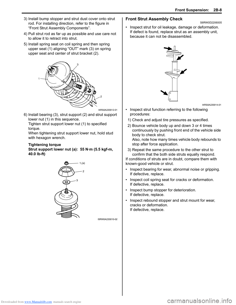
5) Install spring seat on coil spring and then spring
upper seat (1) aligning “OUT” mark (3) on spring
upper seat and center of strut bracket (2).
6) Install bearing (3), strut support (2) and strut support
lower nut (1) in this sequence.
Tighten strut support lower nut (1) to specified
torque.
When tightening strut support lower nut, hold stud
with hexagon wrench.
Tightening torque
Strut support lower nut (a): 55 N·m (5.5 kgf-m,
40.0 lb-ft)Front Strut Assembly CheckS6RW0D2206005
• Inspect strut for oil leakage, damage or deformation.
If defect is found, replace strut as an assembly unit,
because it can not be disassembled.
• Inspect strut function referring to the following
procedures:
1) Check and adjust tire pressures as specified.
2) Bounce vehicle body up and down 3 or 4 times
continuously by pushing front end of the vehicle side
body to check strut.
Also, note how many times vehicle body rebounds to
stop after force application.
3) Repeat the same procedure to the other strut to
confirm that the both side struts equally respond.
If conditions of struts are in doubt, compare them with
known-good vehicle or strut.
• Inspect bearing for wear, abnormal noise or gripping.
If defective, replace.
• Inspect coil spring seat for cracks or deformation.
If defective, replace.
• Inspect bump stopper for deterioration.
If defective, replace.
• Inspect rebound stopper and strut mount for wear,
cracks or deformation.
If defective, replace.
I4RS0A220012-01
3
2
1,(a)
I5RW0A220010-02
I4RS0A220014-01
Page 450 of 1556

Downloaded from www.Manualslib.com manuals search engine 2B-13 Front Suspension:
9) Install ball joint bolt (1), washer (2), strut bracket
bolts (4) and new nuts (3) from the direction shown
in figure.
10) Tighten suspension arm ball joint bolt (2) to specified
torque.
Tightening torque
Suspension arm ball joint bolt (a): 60 N·m (6.0
kgf-m, 43.5 lb-ft)
11) Tighten new strut bracket nuts (3) to specified
torque.
Tightening torque
Strut bracket nut (b): 140 N·m (14.0 kgf-m, 101.5
lb-ft)
CAUTION!
Never reuse the removed strut bracket nut.
12) Install wheel speed sensor (1).
Tightening torque
Wheel speed sensor mounting bolt (a): 11 N·m (
1.1 kgf-m, 8.0 lb-ft)13) Connect tie-rod end (1) to steering knuckle (2),
tighten new nut (3) to specified torque.
Tightening torque
Tie-rod end nut (a): 45 N·m (4.5 kgf-m, 32.5 lb-ft)
14) Install brake disk (2) and brake caliper (3).
15) Tighten caliper carrier bolt to specified torque.
Tightening torque
Caliper carrier bolt: 85 N·m (8.5 kgf-m, 61.5 lb-ft)
16) Depress foot brake pedal and hold it there.
Tighten new drive shaft nut (1) to specified torque.
Tightening torque
Drive shaft nut (a): 200 N·m (20.0 kgf-m, 145.0
lb-ft)
CAUTION!
Never reuse drive shaft nut (1).
17) Caulk drive shaft nut (1) as shown.
CAUTION!
Be careful not to damage the drive shaft nut
while caulking it. If it is damaged, replace it
with new one.
18) Tighten wheel nuts to specified torque.
Tightening torque
Wheel nut: 85 N·m (8.5 kgf-m, 61.5 lb-ft)
19) Confirm front wheel alignment referring to “Front
Wheel Alignment Inspection and Adjustment”.
F: Vehicle front
F
4
3, (b)
2
1, (a)
I7RW01220009-01
1(a)
I5RW0A220017-01
1
3, (a)
2I4RS0B220007-01
I7RW01220013-02
Page 454 of 1556
Downloaded from www.Manualslib.com manuals search engine 2B-17 Front Suspension:
Front Suspension Frame, Stabilizer Bar and/or Bushing ComponentsS6RW0D2206014
123 4
56 7
8 8(c)
(a)
6
(b)
(b)
(c)
(c)
I6RW0D220001-02
1. Stabilizer bar 4. Stabilizer bar mounting
bracket bolt7. Front suspension frame : 95 N⋅m (9.5 kgf-m, 36.5 lb-ft)
2. Stabilizer bushing 5. Suspension control arm 8. Front suspension frame mounting bolt : 150 N⋅m (15.0 kgf-m, 108.5 lb-ft)
3. Stabilizer mounting bracket 6. Suspension control arm
mounting bolt: 23 N⋅m (2.3 kgf-m, 17.0 lb-ft) : Do not reuse.
Page 455 of 1556

Downloaded from www.Manualslib.com manuals search engine Front Suspension: 2B-18
Front Suspension Frame, Stabilizer Bar and/or
Bushing Removal and Installation
S6RW0D2206015
WARNING!
When supporting and installing front
suspension frame, be sure to apply some
supporting equipment (such as mission jack)
at well-balanced position in the center
section of front suspension frame so as to
prevent from its drop. Otherwise drop and
injure.
CAUTION!
When removal and installing suspension
control arm, be careful not to damage dust
boots of suspension control arm joint by
drive shaft dust cover and brake dust cover.
Removal
1) Disconnect negative (–) cable at battery.
2) Remove air cleaner assembly referring to “Air
Cleaner Assembly Removal and Installation in
Section 1D”.
3) Remove hood referring to “Hood Removal and
Installation in Section 9J”.
4) Hoist vehicle and remove front wheels.
5) Remove exhaust No.1, No.2 and center pipes
referring to “Exhaust System Components in Section
1K”.
6) Remove steering gear case mounting bolt referring
to “Steering Gear Case Assembly Components in
Section 6C”.
7) Fix steering gear case to body with rope to avoid the
steering gear case fall off when front suspension
frame is lowered.
8) Remove suspension control arms and disconnect
stabilizer joints.
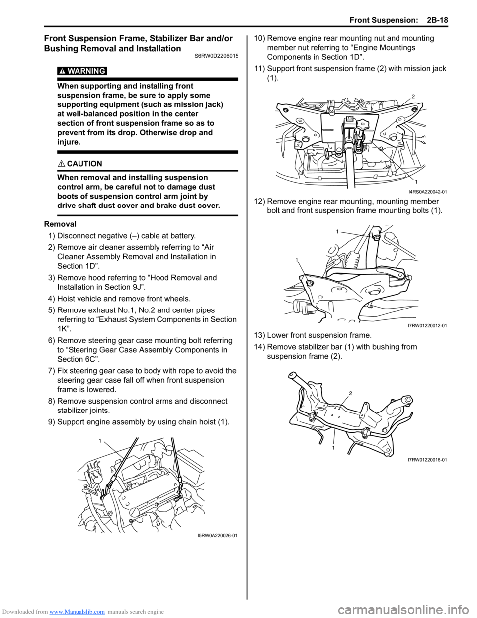
9) Support engine assembly by using chain hoist (1).10) Remove engine rear mounting nut and mounting
member nut referring to “Engine Mountings
Components in Section 1D”.
11) Support front suspension frame (2) with mission jack
(1).
12) Remove engine rear mounting, mounting member
bolt and front suspension frame mounting bolts (1).
13) Lower front suspension frame.
14) Remove stabilizer bar (1) with bushing from
suspension frame (2).
1
I5RW0A220026-01
2
1
I4RS0A220042-01
1
1
I7RW01220012-01
12
I7RW01220016-01