2006 SUZUKI SX4 Suspension
[x] Cancel search: SuspensionPage 1322 of 1556
Downloaded from www.Manualslib.com manuals search engine 9B-3 Lighting Systems:
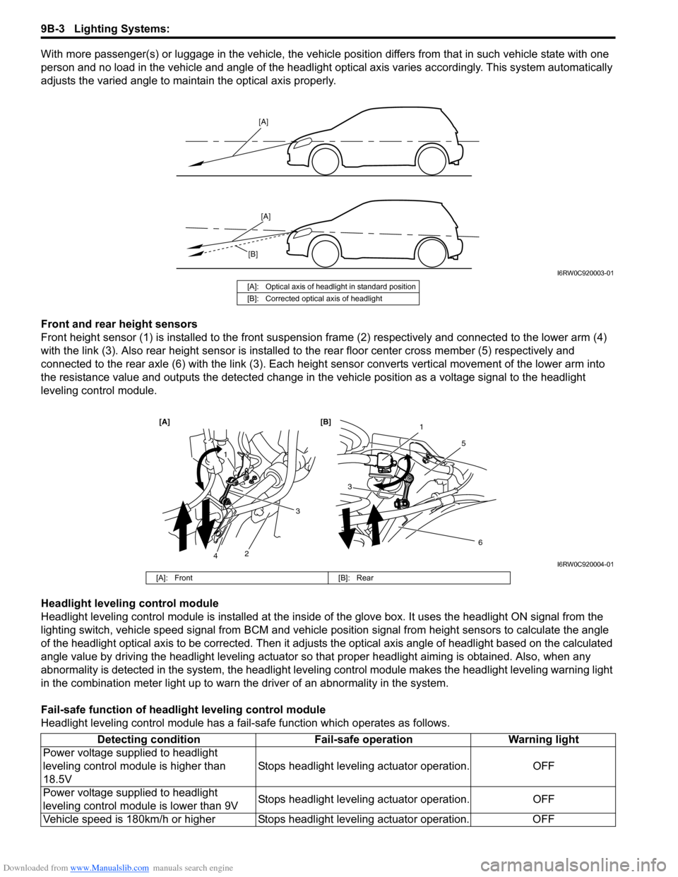
With more passenger(s) or luggage in the vehicle, the vehicle position differs from that in such vehicle state with one
person and no load in the vehicle and angle of the headlight optical axis varies accordingly. This system automatically
adjusts the varied angle to maintain the optical axis properly.
Front and rear height sensors
Front height sensor (1) is installed to the front suspension frame (2) respectively and connected to the lower arm (4)
with the link (3). Also rear height sensor is installed to the rear floor center cross member (5) respectively and
connected to the rear axle (6) with the link (3). Each height sensor converts vertical movement of the lower arm into
the resistance value and outputs the detected change in the vehicle position as a voltage signal to the headlight
leveling control module.
Headlight leveling control module
Headlight leveling control module is installed at the inside of the glove box. It uses the headlight ON signal from the
lighting switch, vehicle speed signal from BCM and vehicle position signal from height sensors to calculate the angle
of the headlight optical axis to be corrected. Then it adjusts the optical axis angle of headlight based on the calculated
angle value by driving the headlight leveling actuator so that proper headlight aiming is obtained. Also, when any
abnormality is detected in the system, the headlight leveling control module makes the headlight leveling warning light
in the combination meter light up to warn the driver of an abnormality in the system.
Fail-safe function of headlight leveling control module
Headlight leveling control module has a fail-safe function which operates as follows.
[A]
[A]
[B]
I6RW0C920003-01
[A]: Optical axis of headlight in standard position
[B]: Corrected optical axis of headlight
1
5
[A] [B]
6
3
1
2
3
4I6RW0C920004-01
[A]: Front [B]: Rear
Detecting condition Fail-safe operation Warning light
Power voltage supplied to headlight
leveling control module is higher than
18.5VStops headlight leveling actuator operation. OFF
Power voltage supplied to headlight
leveling control module is lower than 9VStops headlight leveling actuator operation. OFF
Vehicle speed is 180km/h or higher Stops headlight leveling actuator operation. OFF
Page 1339 of 1556
Downloaded from www.Manualslib.com manuals search engine Lighting Systems: 9B-20
Igniter Removal and Installation (Discharge
Headlight Model)
S6RW0D9206024
WARNING!
Be sure to read “Precautions for Discharge
Headlight Service (If Equipped)” carefully
before working. Neglecting them may result
in personal injury.
Removal
1) Remove ballast referring to “Ballast Removal and
Installation (Discharge Headlight Model)”.
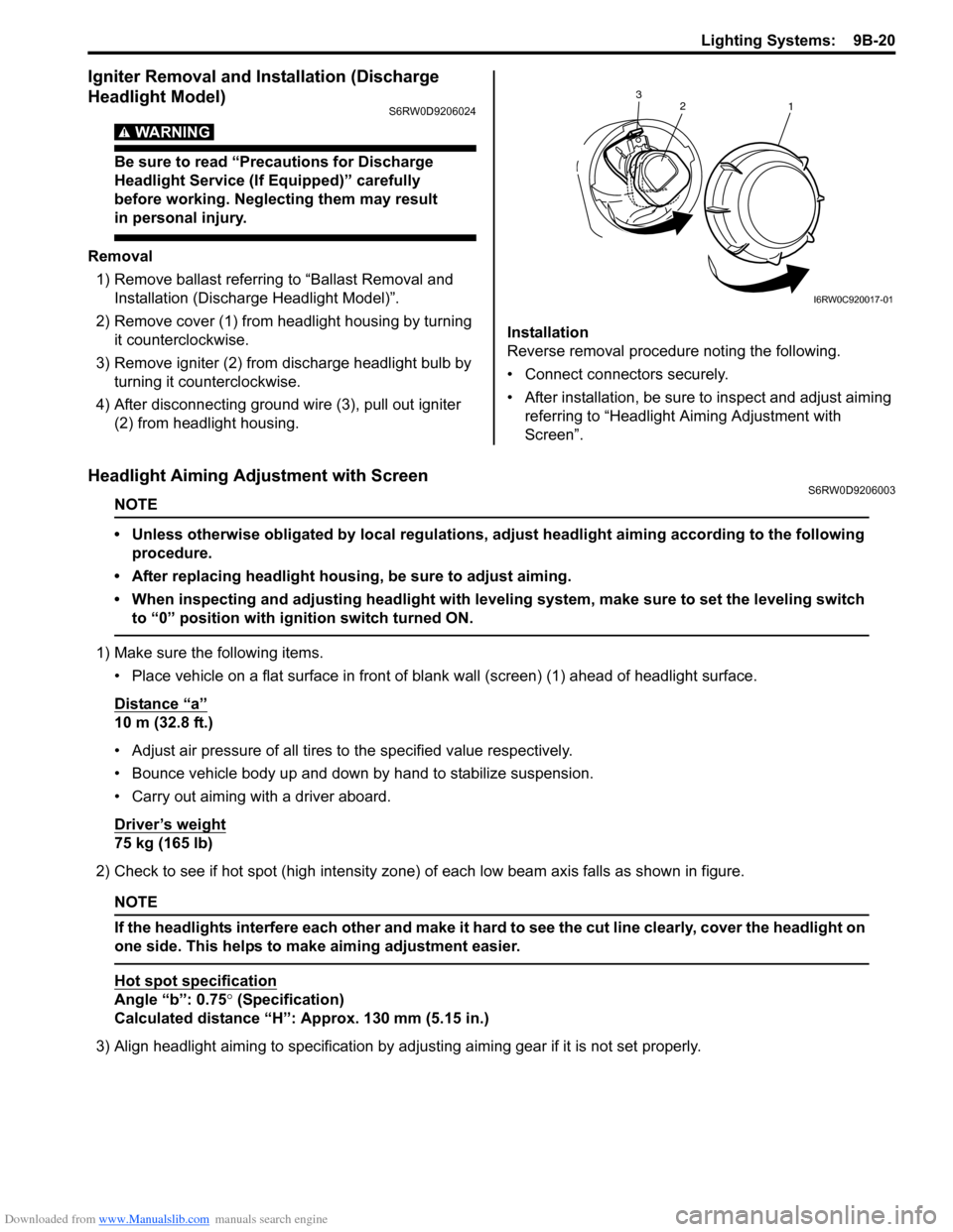
2) Remove cover (1) from headlight housing by turning
it counterclockwise.
3) Remove igniter (2) from discharge headlight bulb by
turning it counterclockwise.
4) After disconnecting ground wire (3), pull out igniter
(2) from headlight housing.Installation
Reverse removal procedure noting the following.
• Connect connectors securely.
• After installation, be sure to inspect and adjust aiming
referring to “Headlight Aiming Adjustment with
Screen”.
Headlight Aiming Adjustment with ScreenS6RW0D9206003
NOTE
• Unless otherwise obligated by local regulations, adjust headlight aiming according to the following
procedure.
• After replacing headlight housing, be sure to adjust aiming.
• When inspecting and adjusting headlight with leveling system, make sure to set the leveling switch
to “0” position with ignition switch turned ON.
1) Make sure the following items.
• Place vehicle on a flat surface in front of blank wall (screen) (1) ahead of headlight surface.
Distance “a”
10 m (32.8 ft.)
• Adjust air pressure of all tires to the specified value respectively.
• Bounce vehicle body up and down by hand to stabilize suspension.
• Carry out aiming with a driver aboard.
Driver’s weight
75 kg (165 lb)
2) Check to see if hot spot (high intensity zone) of each low beam axis falls as shown in figure.
NOTE
If the headlights interfere each other and make it hard to see the cut line clearly, cover the headlight on
one side. This helps to make aiming adjustment easier.
Hot spot specification
Angle “b”: 0.75° (Specification)
Calculated distance “H”: Approx. 130 mm (5.15 in.)
3) Align headlight aiming to specification by adjusting aiming gear if it is not set properly.
2
1 3
I6RW0C920017-01
Page 1345 of 1556
Downloaded from www.Manualslib.com manuals search engine Lighting Systems: 9B-26
Front Fog Light Assembly Removal and
Installation (If Equipped)
S6RW0D9206014
WARNING!
• To avoid danger of being burned, don’t
touch when the bulb is hot.
• Don’t touch glass surface of bulb to avoid
deteriorate as the case may be unclear
when bulb light on at dirty condition.
Removal
1) Disconnect negative (–) cable at battery.
2) Remove front bumper. Refer to “Front Bumper and
Rear Bumper Components in Section 9K”.
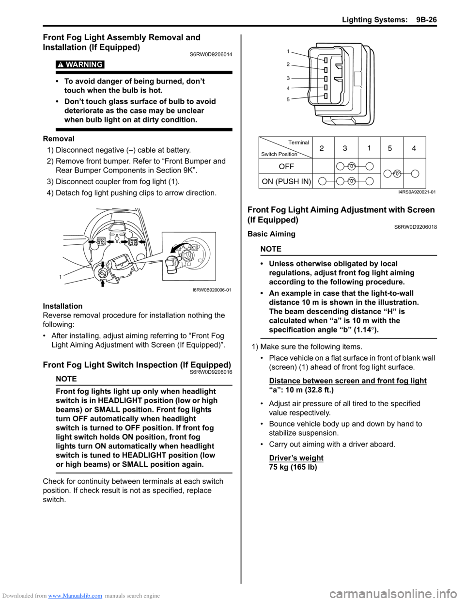
3) Disconnect coupler from fog light (1).
4) Detach fog light pushing clips to arrow direction.
Installation
Reverse removal procedure for installation nothing the
following:
• After installing, adjust aiming referring to “Front Fog
Light Aiming Adjustment with Screen (If Equipped)”.
Front Fog Light Switch Inspection (If Equipped)S6RW0D9206016
NOTE
Front fog lights light up only when headlight
switch is in HEADLIGHT position (low or high
beams) or SMALL position. Front fog lights
turn OFF automatically when headlight
switch is turned to OFF position. If front fog
light switch holds ON position, front fog
lights turn ON automatically when headlight
switch is tuned to HEADLIGHT position (low
or high beams) or SMALL position again.
Check for continuity between terminals at each switch
position. If check result is not as specified, replace
switch.
Front Fog Light Aiming Adjustment with Screen
(If Equipped)
S6RW0D9206018
Basic Aiming
NOTE
• Unless otherwise obligated by local
regulations, adjust front fog light aiming
according to the following procedure.
• An example in case that the light-to-wall
distance 10 m is shown in the illustration.
The beam descending distance “H” is
calculated when “a” is 10 m with the
specification angle “b” (1.14°).
1) Make sure the following items.
• Place vehicle on a flat surface in front of blank wall
(screen) (1) ahead of front fog light surface.
Distance between screen and front fog light
“a”: 10 m (32.8 ft.)
• Adjust air pressure of all tired to the specified
value respectively.
• Bounce vehicle body up and down by hand to
stabilize suspension.
• Carry out aiming with a driver aboard.
Driver’s weight
75 kg (165 lb)
1
I6RW0B920006-01
1
2
3
4
5
Switch PositionTerminal
ON (PUSH IN)231
54
OFF
I4RS0A920021-01
Page 1348 of 1556
Downloaded from www.Manualslib.com manuals search engine 9B-29 Lighting Systems:
Height Sensor Removal and Installation (If
Equipped)
S6RW0D9206027
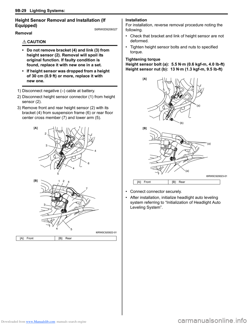
Removal
CAUTION!
• Do not remove bracket (4) and link (3) from
height sensor (2). Removal will spoil its
original function. If faulty condition is
found, replace it with new one in a set.
• If height sensor was dropped from a height
of 30 cm (0.9 ft) or more, replace it with
new one.
1) Disconnect negative (–) cable at battery.
2) Disconnect height sensor connector (1) from height
sensor (2).
3) Remove front and rear height sensor (2) with its
bracket (4) from suspension frame (6) or rear floor
center cross member (7) and lower arm (5).Installation
For installation, reverse removal procedure noting the
following.
• Check that bracket and link of height sensor are not
deformed.
• Tighten height sensor bolts and nuts to specified
torque.
Tightening torque
Height sensor bolt (a): 5.5 N·m (0.6 kgf-m, 4.0 lb-ft)
Height sensor nut (b): 13 N·m (1.3 kgf-m, 9.5 lb-ft)
• Connect connector securely.
• After installation, initialize headlight auto leveling
system referring to “Initialization of Headlight Auto
Leveling System”.
[A]: Front [B]: Rear
12
7
[B] [A]
4
3
2
6
3
5
5
1
4
4
4
I6RW0C920022-01
[A]: Front [B]: Rear
[B] [A]
(b)
(a)
(a)
(a)
I6RW0C920023-01
Page 1349 of 1556
Downloaded from www.Manualslib.com manuals search engine Lighting Systems: 9B-30
Height Sensor and Its Circuit Inspection (If
Equipped)
S6RW0D9206028
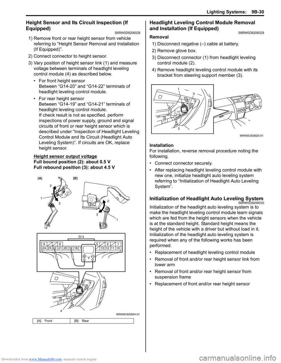
1) Remove front or rear height sensor from vehicle
referring to “Height Sensor Removal and Installation
(If Equipped)”.
2) Connect connector to height sensor.
3) Vary position of height sensor link (1) and measure
voltage between terminals of headlight leveling
control module (4) as described below.
• For front height sensor
Between “G14-20” and “G14-22” terminals of
headlight leveling control module.
• For rear height sensor
Between “G14-19” and “G14-21” terminals of
headlight leveling control module.
If check result is not as specified, perform
inspections of power supply, ground and signal
circuits of front or rear height sensor which is
described under “Inspection of Headlight Leveling
Control Module and Its Circuit (Headlight Auto
Leveling System)”. If circuits are OK, replace
height sensor.
Height sensor output voltage
Full bound position (2): about 0.5 V
Full rebound position (3): about 4.5 V
Headlight Leveling Control Module Removal
and Installation (If Equipped)
S6RW0D9206029
Removal
1) Disconnect negative (–) cable at battery.
2) Remove glove box.
3) Disconnect connector (1) from headlight leveling
control module (2).
4) Remove headlight leveling control module with its
bracket from steering support member (3).
Installation
For installation, reverse removal procedure noting the
following.
• Connect connector securely.
• After replacing headlight leveling control module with
new one, initialize headlight auto leveling system
referring to “Initialization of Headlight Auto Leveling
System”.
Initialization of Headlight Auto Leveling SystemS6RW0D9206030
Initialization of the headlight auto leveling system is to
make the headlight leveling control module learn signals
which are fed from the height sensors when the vehicle
is at the standard height. Standard height means the
height of the vehicle with a driver but without load in it.
Initialization of the headlight auto leveling system is
required when any of the following works has been
performed.
• Replacement of headlight leveling control module
• Removal of front and/or rear height sensor link from
lower arm
• Removal of front and/or rear height sensor from
suspension frame
• Replacement of front and/or rear height sensor
[A]: Front [B]: Rear
[A] [B]
4
G14
10 11 12 13 16 17 18 19 2031 5 6 9
21 22 23 24
V
2
3 1
2
3
1
I6RW0C920024-01
23 1
I6RW0C920025-01
Page 1350 of 1556
Downloaded from www.Manualslib.com manuals search engine 9B-31 Lighting Systems:
Without initialization of the headlight auto leveling
system, it is not possible to obtain its proper function.
Also, if the headlight auto leveling system is not
initialized after replacing the headlight leveling control
module, the headlight leveling warning light in the
combination meter flashes.
1) Observe the following instructions.
• Park vehicle on level ground.
• Adjust air pressure of all tires to the specified
value respectively.
• Bounce vehicle body up and down by hand to
stabilize suspension.
2) Turn ignition switch to ON position.
3) Perform “Headlight Leveling Warning Light Check”.
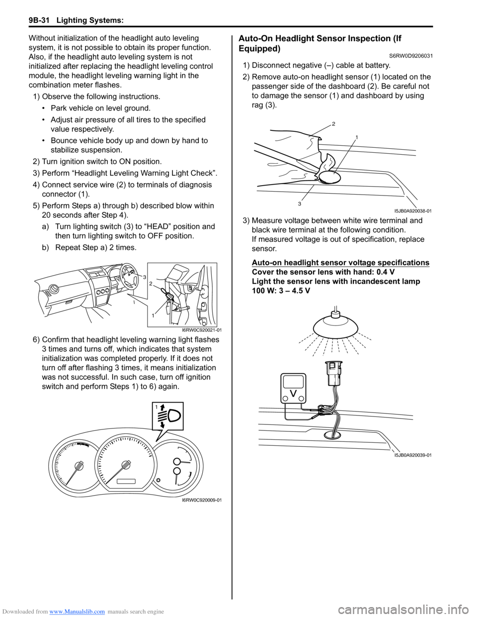
4) Connect service wire (2) to terminals of diagnosis
connector (1).
5) Perform Steps a) through b) described blow within
20 seconds after Step 4).
a) Turn lighting switch (3) to “HEAD” position and
then turn lighting switch to OFF position.
b) Repeat Step a) 2 times.
6) Confirm that headlight leveling warning light flashes
3 times and turns off, which indicates that system
initialization was completed properly. If it does not
turn off after flashing 3 times, it means initialization
was not successful. In such case, turn off ignition
switch and perform Steps 1) to 6) again.Auto-On Headlight Sensor Inspection (If
Equipped)
S6RW0D9206031
1) Disconnect negative (–) cable at battery.
2) Remove auto-on headlight sensor (1) located on the
passenger side of the dashboard (2). Be careful not
to damage the sensor (1) and dashboard by using
rag (3).
3) Measure voltage between white wire terminal and
black wire terminal at the following condition.
If measured voltage is out of specification, replace
sensor.
Auto-on headlight sensor voltage specifications
Cover the sensor lens with hand: 0.4 V
Light the sensor lens with incandescent lamp
100 W: 3 – 4.5 V3
1
2
I6RW0C920021-01
1
I6RW0C920009-01
2
1
3I5JB0A920038-01
I5JB0A920039-01
Page 1451 of 1556
Downloaded from www.Manualslib.com manuals search engine Body Structure: 9K-7
Under Body
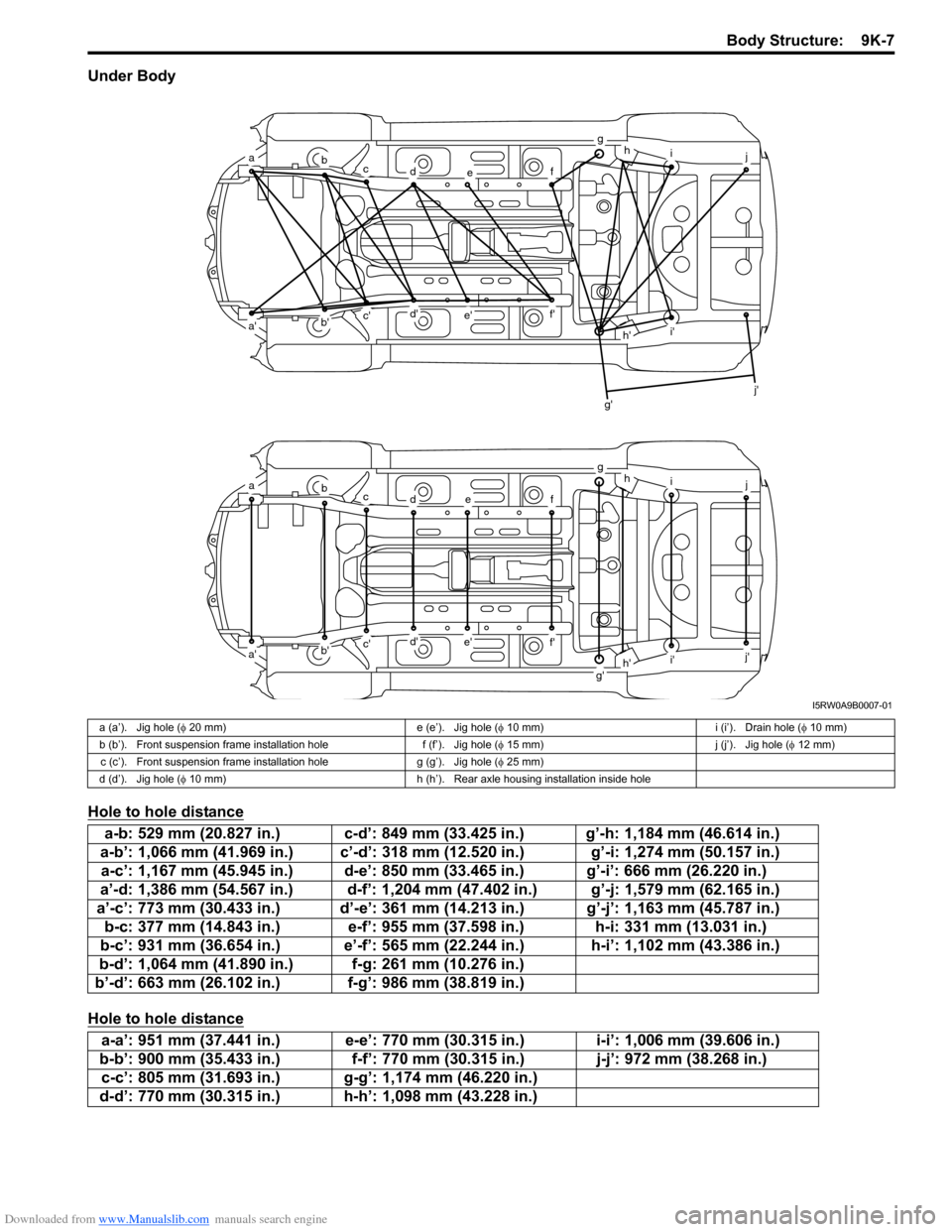
Hole to hole distance
Hole to hole distance
abcdef
ghij
a'b'c'd'e'f'
g'
h'i'
j'
abcdef
ghij
a'b'c'd'e'f'
g'h'i'j'
I5RW0A9B0007-01
a (a’). Jig hole (φ 20 mm) e (e’). Jig hole (φ 10 mm) i (i’). Drain hole (φ 10 mm)
b (b’). Front suspension frame installation hole f (f’). Jig hole (φ 15 mm) j (j’). Jig hole (φ 12 mm)
c (c’). Front suspension frame installation hole g (g’). Jig hole (φ 25 mm)
d (d’). Jig hole (φ 10 mm) h (h’). Rear axle housing installation inside hole
a-b: 529 mm (20.827 in.) c-d’: 849 mm (33.425 in.) g’-h: 1,184 mm (46.614 in.)
a-b’: 1,066 mm (41.969 in.) c’-d’: 318 mm (12.520 in.) g’-i: 1,274 mm (50.157 in.)
a-c’: 1,167 mm (45.945 in.) d-e’: 850 mm (33.465 in.) g’-i’: 666 mm (26.220 in.)
a’-d: 1,386 mm (54.567 in.) d-f’: 1,204 mm (47.402 in.) g’-j: 1,579 mm (62.165 in.)
a’-c’: 773 mm (30.433 in.) d’-e’: 361 mm (14.213 in.) g’-j’: 1,163 mm (45.787 in.)
b-c: 377 mm (14.843 in.) e-f’: 955 mm (37.598 in.) h-i: 331 mm (13.031 in.)
b-c’: 931 mm (36.654 in.) e’-f’: 565 mm (22.244 in.) h-i’: 1,102 mm (43.386 in.)
b-d’: 1,064 mm (41.890 in.) f-g: 261 mm (10.276 in.)
b’-d’: 663 mm (26.102 in.) f-g’: 986 mm (38.819 in.)
a-a’: 951 mm (37.441 in.) e-e’: 770 mm (30.315 in.) i-i’: 1,006 mm (39.606 in.)
b-b’: 900 mm (35.433 in.) f-f’: 770 mm (30.315 in.) j-j’: 972 mm (38.268 in.)
c-c’: 805 mm (31.693 in.) g-g’: 1,174 mm (46.220 in.)
d-d’: 770 mm (30.315 in.) h-h’: 1,098 mm (43.228 in.)
Page 1452 of 1556
Downloaded from www.Manualslib.com manuals search engine 9K-8 Body Structure:
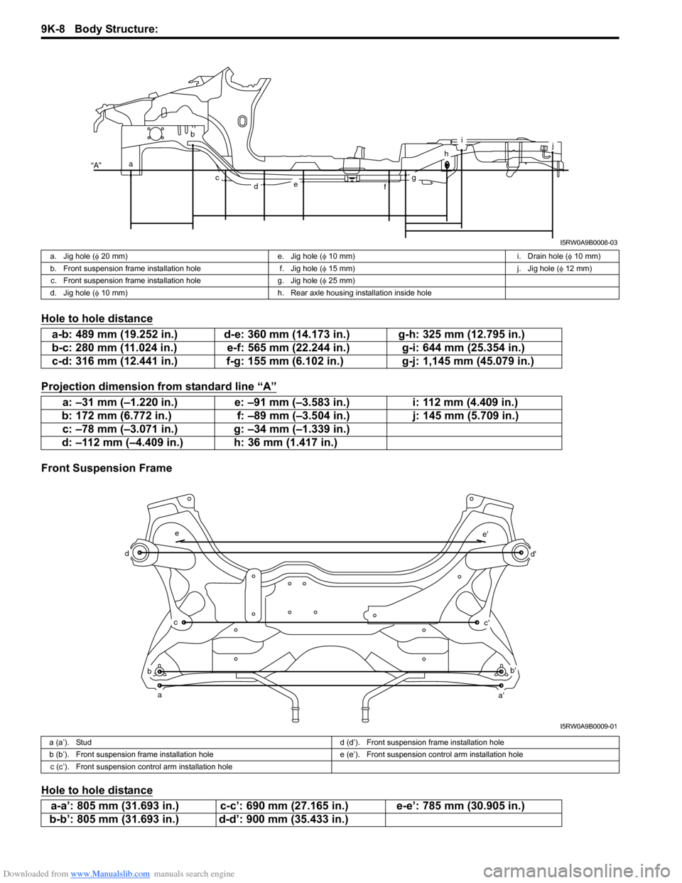
Hole to hole distance
Projection dimension from standard line “A”
Front Suspension Frame
Hole to hole distance
a
b
cdefg
h
ij
“A”
I5RW0A9B0008-03
a. Jig hole (φ 20 mm) e. Jig hole (φ 10 mm) i. Drain hole (φ 10 mm)
b. Front suspension frame installation hole f. Jig hole (φ 15 mm) j. Jig hole (φ 12 mm)
c. Front suspension frame installation hole g. Jig hole (φ 25 mm)
d. Jig hole (φ 10 mm) h. Rear axle housing installation inside hole
a-b: 489 mm (19.252 in.) d-e: 360 mm (14.173 in.) g-h: 325 mm (12.795 in.)
b-c: 280 mm (11.024 in.) e-f: 565 mm (22.244 in.) g-i: 644 mm (25.354 in.)
c-d: 316 mm (12.441 in.) f-g: 155 mm (6.102 in.) g-j: 1,145 mm (45.079 in.)
a: –31 mm (–1.220 in.) e: –91 mm (–3.583 in.) i: 112 mm (4.409 in.)
b: 172 mm (6.772 in.) f: –89 mm (–3.504 in.) j: 145 mm (5.709 in.)
c: –78 mm (–3.071 in.) g: –34 mm (–1.339 in.)
d: –112 mm (–4.409 in.) h: 36 mm (1.417 in.)
a
b
c
d
e
a'
b'
c'
d'
e'
I5RW0A9B0009-01
a (a’). Studd (d’). Front suspension frame installation hole
b (b’). Front suspension frame installation hole e (e’). Front suspension control arm installation hole
c (c’). Front suspension control arm installation hole
a-a’: 805 mm (31.693 in.) c-c’: 690 mm (27.165 in.) e-e’: 785 mm (30.905 in.)
b-b’: 805 mm (31.693 in.) d-d’: 900 mm (35.433 in.)