2006 SUZUKI SX4 inspection cylinder
[x] Cancel search: inspection cylinderPage 877 of 1556

Downloaded from www.Manualslib.com manuals search engine Steering Wheel and Column: 6B-8
3) Align flat part “a” of steering lower shaft (1) with bolt
hole “b” of shaft joint (2) of column as shown. Then
insert lower shaft into shaft joint of steering column.
4) Tighten lower shaft upper joint bolt (3) to specified
torque.
CAUTION!
After tightening column nuts, tighten steering
shaft upper joint bolt. Otherwise, shaft joint
bearing is damaged.
Tightening torque
Steering lower shaft assembly upper joint bolt
(a): 25 N·m (2.5 kgf-m, 18.5 lb-ft)
5) Install lighting switch and wiper switch to steering
column.
6) (Immobilizer model)
Install immobilizer control module from steering
column, referring to “ICM Removal and Installation in
Section 10C”.
7) Install contact coil cable assembly and steering
wheel referring to “Contact Coil Cable Assembly
Removal and Installation” and “Steering Wheel
Removal and Installation”.
8) Connect negative (–) cable to battery.
9) Enable air bag system referring to “Enabling Air Bag
System in Section 8B”.
Steering Column InspectionS6RW0D6206009
Check steering column for damage and operation
referring to “Checking Steering Column for Accident
Damage”.
Ignition Switch Cylinder Assembly Removal
and Installation (Non- Keyless Start Model)
S6RW0D6206010
Removal
1) Disconnect negative (–) cable at battery.
2) Disable air bag system referring to “Disabling Air
Bag System in Section 8B”.
3) Remove steering column upper and lower covers.
4) (Immobilizer model)
Remove immobilizer control module referring to
“ICM Removal and Installation in Section 10C”.
5) Remove ignition switch cylinder assembly as follows.
a) Turn ignition key to “ACC” position.
b) Insert 2 mm (0.078 in.) rod (2) through hole (3)
and push ignition switch cylinder lock.
c) Detach ignition switch cylinder assembly (1) from
steering lock assembly (4).
Installation
1) Install ignition switch cylinder assembly as follows.
a) Turn ignition key to “ACC” position.
b) In this state, push ignition switch cylinder
assembly into steering lock assembly till it clicks.
2) (Immobilizer model)
Install immobilizer control module referring to “ICM
Removal and Installation in Section 10C”.
3) Install upper and lower cover and screws.
4) Connect negative (–) cable to battery.
5) Enabling air bag system referring to “Enabling Air
Bag System in Section 8B”.
6) (Immobilizer model)
If ignition switch cylinder assembly (that is ignition
key) has replaced, register ignition key transponder
code to ECM referring to “Registration of the Ignition
Key in Section 10C”.
1 2
“a”“b”
3, (a)
I5RW0A620007-01
2
3
1
4
I5JB0A620025-01
Page 917 of 1556

Downloaded from www.Manualslib.com manuals search engine Power Assisted Steering System: 6C-37
3) Inspect for proper toe referring to “Front Wheel
Alignment Inspection and Adjustment in Section 2B”.
4) After confirming proper toe, tighten tie-rod end lock
nut to specified torque.
Tightening torque
Tie-rod end lock nut (a): 45 N·m (4.5 kgf-m, 32.5
lb-ft)
5) Tighten wheel bolts to specified torque and lower
hoist.
Tightening torque
Wheel bolt: 85 N·m (8.5 kgf-m, 61.5 lb-ft)
Tie-Rod End InspectionS6RW0D6306004
• Inspect for play in ball joint.
• Inspect for play in rack end ball joint.
In either case, if found defective, replace.
Steering Shaft Joint On-Vehicle InspectionS6RW0D6306005
Check shaft joint for wear, breakage and any other
damage and replace if any defect exists.
Steering Gear Case Assembly Removal and
Installation
S6RW0D6306006
Removal
CAUTION!
Be sure to set front wheels (tires) in straight
direction and remove ignition key from key
cylinder before performing the following
steps, otherwise, contact coil of air bag
system may get damaged.
1) Remove steering joint cover.
2) Make alignment marks (1) on pinion shaft (2) and
joint of steering lower shaft (3) for a guide during
reinstallation.
3) Loosen joint bolt (steering column side) (4) and
remove joint bolt (pinion shaft side) (5) and
disconnect steering lower shaft (3) from pinion shaft
(2).
4) Disconnect torque sensor connector and P/S motor
connector from steering gear case.
5) Remove front suspension frame referring to “Front
Suspension Frame, Stabilizer Bar and/or Bushing
Removal and Installation in Section 2B”, and then
remove steering gear case.
Installation
1) Install grommet (1) as shown in figure.
I3RM0A630030-01
I4RS0A630043-01
I4RS0B630012-01
2. Protrusion
5
2
1
5
34
3
I4RS0B630013-01
1
2
1
2
I5RW0A630018-02
Page 1165 of 1556
Downloaded from www.Manualslib.com manuals search engine Table of Contents 9-v
Power Door Lock System Symptom
Diagnosis (If Equipped)..................................... 9F-3
Power Door Lock System Operation
Inspection (If Equipped) .................................... 9F-3
Keyless Entry System Symptom Diagnosis (If
Equipped).......................................................... 9F-4
Keyless Entry System Operation Inspection
(If Equipped) ..................................................... 9F-5
Door Lock Function of Keyless Start System
Symptom Diagnosis (If Equipped) .................... 9F-5
Rear End Door Opener System Symptom
Diagnosis (If Equipped)..................................... 9F-5
Rear End Door Opener System Operation
Inspection (If Equipped) .................................... 9F-5
Repair Instructions .............................................. 9F-6
Front Door Lock Assembly Components ............ 9F-6
Front Door Lock Assembly Removal and
Installation ......................................................... 9F-6
Front Door Lock Assembly Inspection ................ 9F-8
Power Door Lock Switch Inspection (If
Equipped).......................................................... 9F-8
Door Key Cylinder Switch Inspection (If
Equipped).......................................................... 9F-8
Power Door Lock Actuator Inspection (If
Equipped).......................................................... 9F-9
Rear Door Lock Assembly Components ........... 9F-10
Rear Door Lock Assembly Removal and
Installation ....................................................... 9F-10
Rear Door Lock Assembly Inspection ............... 9F-10
Rear End Door Lock Assembly Components.... 9F-11
Rear End Door Lock Assembly Removal and
Installation ....................................................... 9F-12
Rear End Door Lock Assembly Inspection........ 9F-12
Rear End Door Opener Switch Inspection (If
Equipped)........................................................ 9F-12
Replacement of Transmitter Battery (Other
than Keyless Start Model) ............................... 9F-13
Programming Transmitter Code for Keyless
Entry System (Other than Keyless Start
Model) ............................................................. 9F-13
Keyless Entry Answer Back Function
Change-over Procedure (If Equipped) ............ 9F-14
Keyless Entry Receiver Removal and
Installation (If Equipped)................................. 9F-14
Keyless Entry Receiver and Its Circuit
Inspection (If Equipped) .................................. 9F-15
Specifications..................................................... 9F-16
Tightening Torque Specifications ...................... 9F-16
Special Tools and Equipment ........................... 9F-16
Recommended Service Material ....................... 9F-16
Seats ......................................................... 9G-1
Diagnostic Information and Procedures ............9G-1
Front Seat Heater Symptom Diagnosis (If
Equipped)..........................................................9G-1
Repair Instructions ..............................................9G-2
Front Seat Components ......................................9G-2
Front Seat Removal and Installation ...................9G-3Front Seat Heater Switch (Driver and
Passenger Side) Inspection (If Equipped)........ 9G-3
Front Seat Heater Wire Inspection (If
Equipped) ......................................................... 9G-3
Rear Seat Components...................................... 9G-4
Rear Seat Removal and Installation................... 9G-4
Specifications ...................................................... 9G-5
Tightening Torque Specifications ....................... 9G-5
Special Tools and Equipment ............................ 9G-5
Recommended Service Material ........................ 9G-5
Interior Trim ............................................. 9H-1
Repair Instructions ..............................................9H-1
Floor Carpet Removal and Installation ................9H-1
Head Lining Removal and Installation.................9H-2
Console Box Components ..................................9H-3
Specifications .......................................................9H-4
Tightening Torque Specifications ........................9H-4
Hood / Fenders / Doors ............................ 9J-1
Repair Instructions .............................................. 9J-1
Hood Removal and Installation ........................... 9J-1
Hood Inspection and Adjustment ........................ 9J-1
Front Fender Components .................................. 9J-2
Front Fender Removal and Installation ............... 9J-2
Front Door Assembly Components ..................... 9J-3
Front Door Assembly Removal and
Installation ......................................................... 9J-3
Rear Door Assembly Components...................... 9J-5
Rear Door Assembly Removal and
Installation ......................................................... 9J-5
Rear End Door Assembly Components .............. 9J-6
Rear End Door Assembly Removal and
Installation ......................................................... 9J-6
Specifications ....................................................... 9J-8
Tightening Torque Specifications ........................ 9J-8
Special Tools and Equipment ............................. 9J-8
Recommended Service Material ......................... 9J-8
Body Structure......................................... 9K-1
Repair Instructions ..............................................9K-1
Front Bumper and Rear Bumper Components .... 9K-1
Cowl Top and Front Lower Crossmember
Components ...................................................... 9K-2
Specifications .......................................................9K-3
Body Dimensions ................................................ 9K-3
Panel Clearance................................................ 9K-10
Tightening Torque Specifications ...................... 9K-10
Paint / Coatings ........................................9L-1
General Description ............................................. 9L-1
Anti-Corrosion Treatment Construction............... 9L-1
Plastic Parts Finishing ......................................... 9L-2
Component Location ........................................... 9L-3
Sealant Application Areas ................................... 9L-3
Under Coating Application Areas ...................... 9L-10
Anti-Corrosion Compound Application Area ..... 9L-12
Exterior Trim ............................................ 9M-1
Page 1366 of 1556
Downloaded from www.Manualslib.com manuals search engine 9C-14 Instrumentation / Driver Info. / Horn:
Repair Instructions
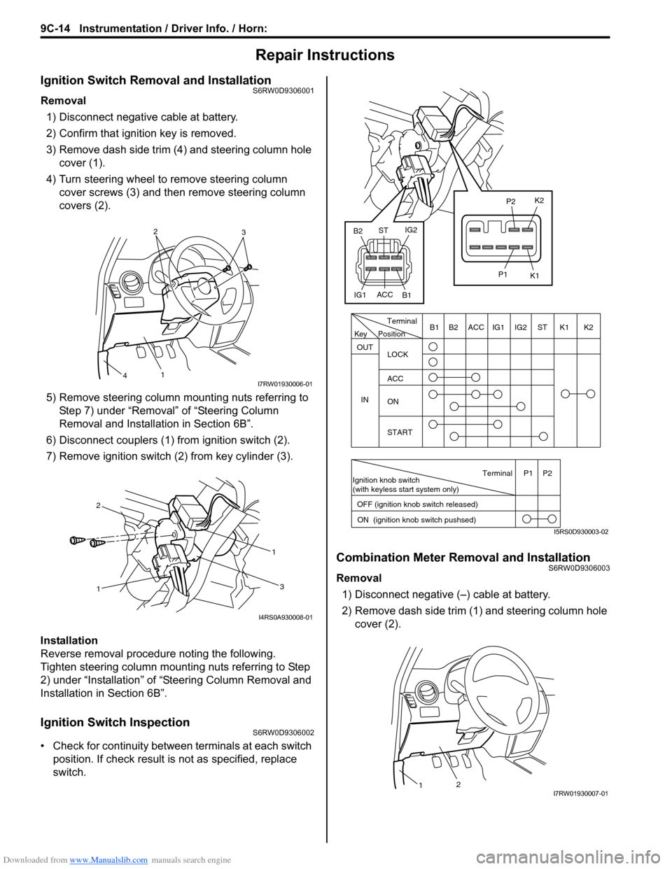
Ignition Switch Removal and InstallationS6RW0D9306001
Removal
1) Disconnect negative cable at battery.
2) Confirm that ignition key is removed.
3) Remove dash side trim (4) and steering column hole
cover (1).
4) Turn steering wheel to remove steering column
cover screws (3) and then remove steering column
covers (2).
5) Remove steering column mounting nuts referring to
Step 7) under “Removal” of “Steering Column
Removal and Installation in Section 6B”.
6) Disconnect couplers (1) from ignition switch (2).
7) Remove ignition switch (2) from key cylinder (3).
Installation
Reverse removal procedure noting the following.
Tighten steering column mounting nuts referring to Step
2) under “Installation” of “Steering Column Removal and
Installation in Section 6B”.
Ignition Switch InspectionS6RW0D9306002
• Check for continuity between terminals at each switch
position. If check result is not as specified, replace
switch.
Combination Meter Removal and InstallationS6RW0D9306003
Removal
1) Disconnect negative (–) cable at battery.
2) Remove dash side trim (1) and steering column hole
cover (2).
2
3
1
4I7RW01930006-01
11
2
3
I4RS0A930008-01
PositionTerminal
LOCK
ACC
ON
START OUT
INK2 K1 ST IG2 IG1 ACC B1 B2
Ignition knob switch
(with keyless start system only)
ACC
IG1IG2
ST
B2
B1K2
K1
P2
P1
Terminal
OFF (ignition knob switch released)
ON (ignition knob switch pushsed)P1 P2
Key
I5RS0D930003-02
21I7RW01930007-01
Page 1367 of 1556
Downloaded from www.Manualslib.com manuals search engine Instrumentation / Driver Info. / Horn: 9C-15
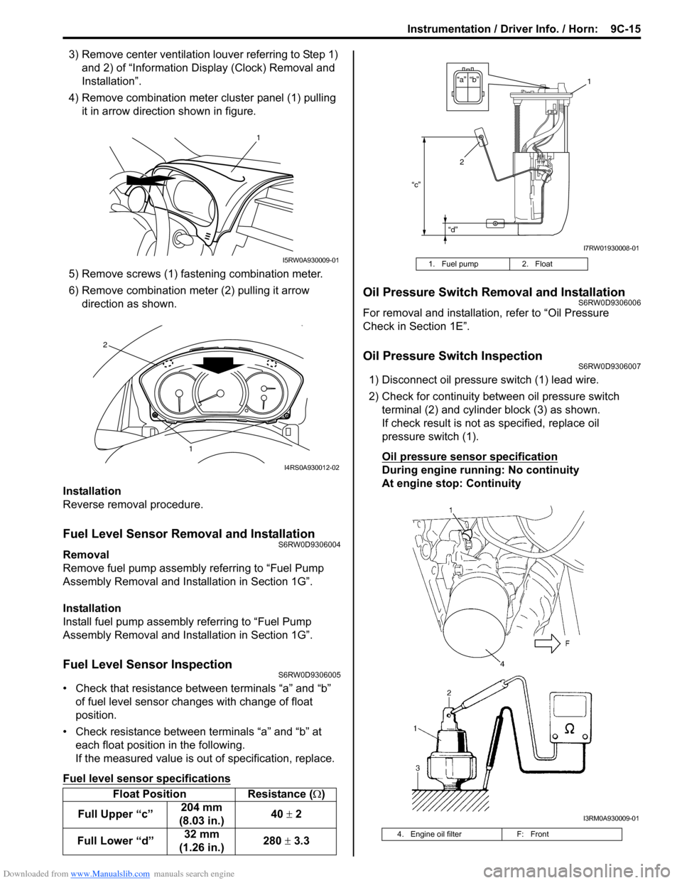
3) Remove center ventilation louver referring to Step 1)
and 2) of “Information Display (Clock) Removal and
Installation”.
4) Remove combination meter cluster panel (1) pulling
it in arrow direction shown in figure.
5) Remove screws (1) fastening combination meter.
6) Remove combination meter (2) pulling it arrow
direction as shown.
Installation
Reverse removal procedure.
Fuel Level Sensor Removal and InstallationS6RW0D9306004
Removal
Remove fuel pump assembly referring to “Fuel Pump
Assembly Removal and Installation in Section 1G”.
Installation
Install fuel pump assembly referring to “Fuel Pump
Assembly Removal and Installation in Section 1G”.
Fuel Level Sensor InspectionS6RW0D9306005
• Check that resistance between terminals “a” and “b”
of fuel level sensor changes with change of float
position.
• Check resistance between terminals “a” and “b” at
each float position in the following.
If the measured value is out of specification, replace.
Fuel level sensor specifications
Oil Pressure Switch Removal and InstallationS6RW0D9306006
For removal and installation, refer to “Oil Pressure
Check in Section 1E”.
Oil Pressure Switch InspectionS6RW0D9306007
1) Disconnect oil pressure switch (1) lead wire.
2) Check for continuity between oil pressure switch
terminal (2) and cylinder block (3) as shown.
If check result is not as specified, replace oil
pressure switch (1).
Oil pressure sensor specification
During engine running: No continuity
At engine stop: Continuity
Float Position Resistance (Ω)
Full Upper “c”204 mm
(8.03 in.)40 ± 2
Full Lower “d”32 mm
(1.26 in.)280 ± 3.3
1
I5RW0A930009-01
1
2
I4RS0A930012-02
1. Fuel pump 2. Float
4. Engine oil filter F: Front
“c”
“d”
“b” “a”1
2
I7RW01930008-01
I3RM0A930009-01
Page 1414 of 1556
Downloaded from www.Manualslib.com manuals search engine 9F-3 Security and Locks:
Diagnostic Information and Procedures
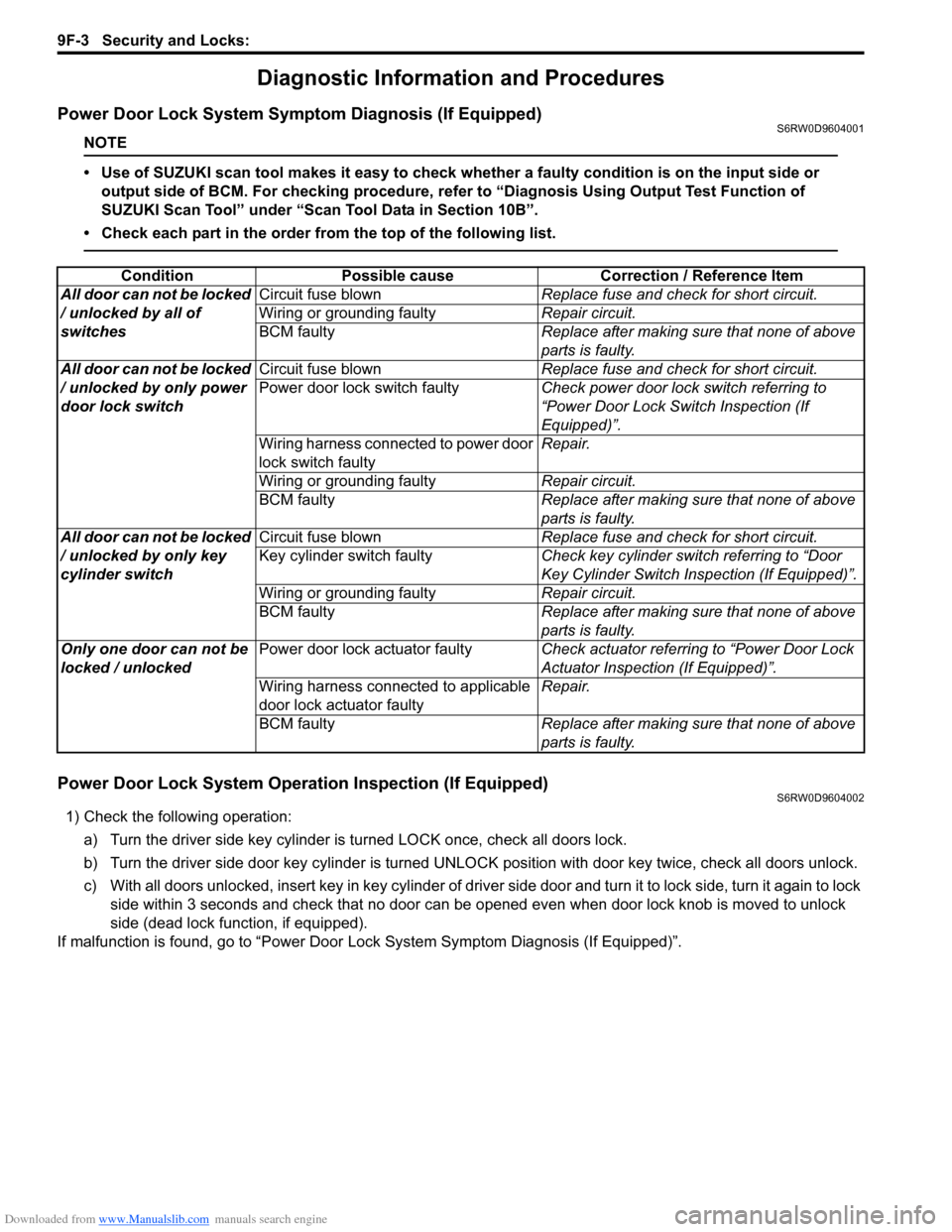
Power Door Lock System Symptom Diagnosis (If Equipped)S6RW0D9604001
NOTE
• Use of SUZUKI scan tool makes it easy to check whether a faulty condition is on the input side or
output side of BCM. For checking procedure, refer to “Diagnosis Using Output Test Function of
SUZUKI Scan Tool” under “Scan Tool Data in Section 10B”.
• Check each part in the order from the top of the following list.
Power Door Lock System Operation Inspection (If Equipped)S6RW0D9604002
1) Check the following operation:
a) Turn the driver side key cylinder is turned LOCK once, check all doors lock.
b) Turn the driver side door key cylinder is turned UNLOCK position with door key twice, check all doors unlock.
c) With all doors unlocked, insert key in key cylinder of driver side door and turn it to lock side, turn it again to lock
side within 3 seconds and check that no door can be opened even when door lock knob is moved to unlock
side (dead lock function, if equipped).
If malfunction is found, go to “Power Door Lock System Symptom Diagnosis (If Equipped)”. Condition Possible cause Correction / Reference Item
All door can not be locked
/ unlocked by all of
switchesCircuit fuse blownReplace fuse and check for short circuit.
Wiring or grounding faultyRepair circuit.
BCM faultyReplace after making sure that none of above
parts is faulty.
All door can not be locked
/ unlocked by only power
door lock switchCircuit fuse blownReplace fuse and check for short circuit.
Power door lock switch faultyCheck power door lock switch referring to
“Power Door Lock Switch Inspection (If
Equipped)”.
Wiring harness connected to power door
lock switch faultyRepair.
Wiring or grounding faultyRepair circuit.
BCM faultyReplace after making sure that none of above
parts is faulty.
All door can not be locked
/ unlocked by only key
cylinder switchCircuit fuse blownReplace fuse and check for short circuit.
Key cylinder switch faultyCheck key cylinder switch referring to “Door
Key Cylinder Switch Inspection (If Equipped)”.
Wiring or grounding faultyRepair circuit.
BCM faultyReplace after making sure that none of above
parts is faulty.
Only one door can not be
locked / unlockedPower door lock actuator faultyCheck actuator referring to “Power Door Lock
Actuator Inspection (If Equipped)”.
Wiring harness connected to applicable
door lock actuator faultyRepair.
BCM faultyReplace after making sure that none of above
parts is faulty.
Page 1416 of 1556
Downloaded from www.Manualslib.com manuals search engine 9F-5 Security and Locks:
Keyless Entry System Operation Inspection (If
Equipped)
S6RW0D9604004
NOTE
When performing the this inspection, make
sure to have any of the door once opened /
closed after the ignition key has been
removed from the ignition key cylinder.
1) Confirm that power door lock system operates
normally, refer to “Power Door Lock System
Operation Inspection (If Equipped)”.
2) All doors are closed and unlocked.
3) Check the following operation:
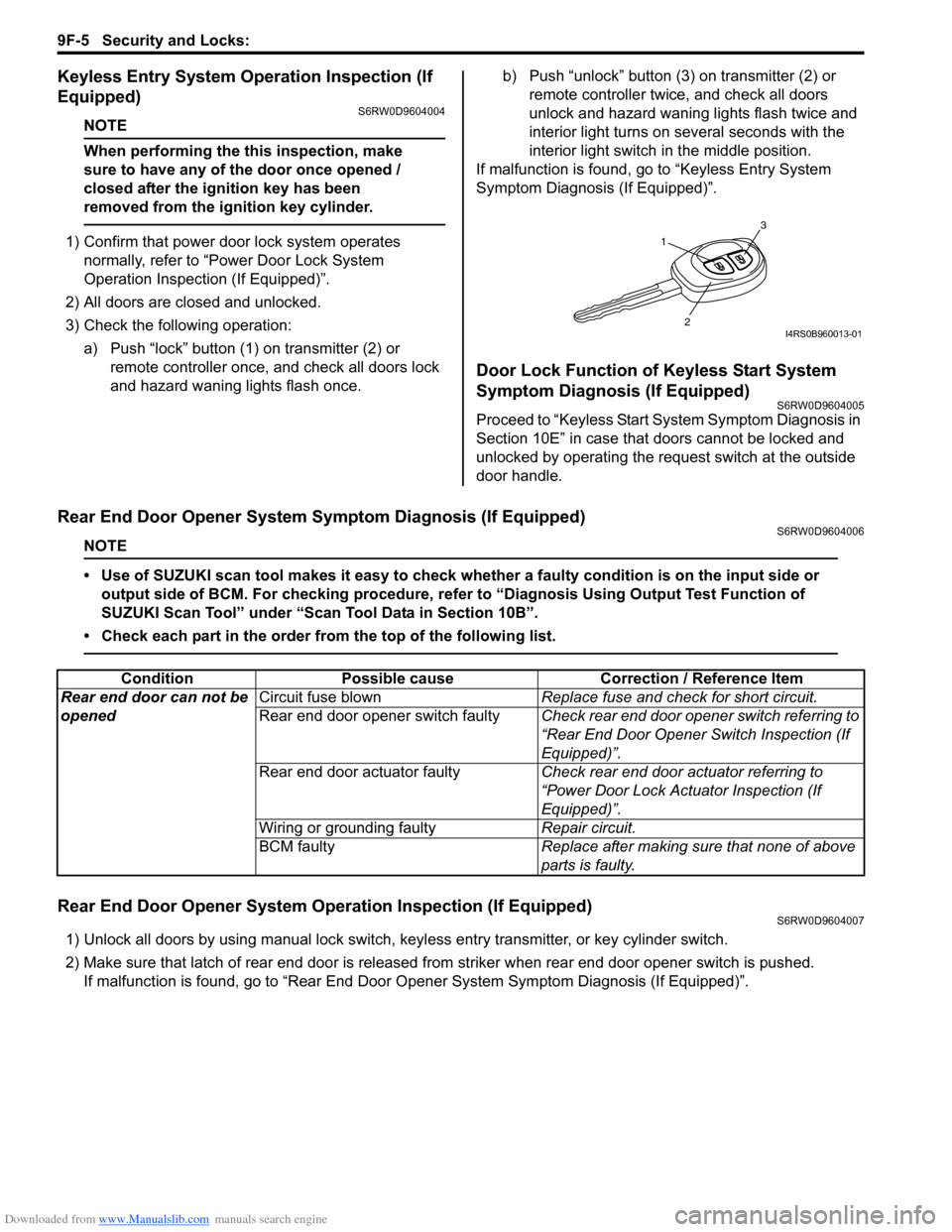
a) Push “lock” button (1) on transmitter (2) or
remote controller once, and check all doors lock
and hazard waning lights flash once.b) Push “unlock” button (3) on transmitter (2) or
remote controller twice, and check all doors
unlock and hazard waning lights flash twice and
interior light turns on several seconds with the
interior light switch in the middle position.
If malfunction is found, go to “Keyless Entry System
Symptom Diagnosis (If Equipped)”.
Door Lock Function of Keyless Start System
Symptom Diagnosis (If Equipped)
S6RW0D9604005
Proceed to “Keyless Start System Symptom Diagnosis in
Section 10E” in case that doors cannot be locked and
unlocked by operating the request switch at the outside
door handle.
Rear End Door Opener System Symptom Diagnosis (If Equipped)S6RW0D9604006
NOTE
• Use of SUZUKI scan tool makes it easy to check whether a faulty condition is on the input side or
output side of BCM. For checking procedure, refer to “Diagnosis Using Output Test Function of
SUZUKI Scan Tool” under “Scan Tool Data in Section 10B”.
• Check each part in the order from the top of the following list.
Rear End Door Opener System Operation Inspection (If Equipped)S6RW0D9604007
1) Unlock all doors by using manual lock switch, keyless entry transmitter, or key cylinder switch.
2) Make sure that latch of rear end door is released from striker when rear end door opener switch is pushed.
If malfunction is found, go to “Rear End Door Opener System Symptom Diagnosis (If Equipped)”.
1
3
2I4RS0B960013-01
Condition Possible cause Correction / Reference Item
Rear end door can not be
openedCircuit fuse blownReplace fuse and check for short circuit.
Rear end door opener switch faultyCheck rear end door opener switch referring to
“Rear End Door Opener Switch Inspection (If
Equipped)”.
Rear end door actuator faultyCheck rear end door actuator referring to
“Power Door Lock Actuator Inspection (If
Equipped)”.
Wiring or grounding faultyRepair circuit.
BCM faultyReplace after making sure that none of above
parts is faulty.
Page 1419 of 1556
Downloaded from www.Manualslib.com manuals search engine Security and Locks: 9F-8
Front Door Lock Assembly InspectionS6RW0D9606003
• Check that door open and closes smoothly and
properly.
• Check that door stops in the secondary latched
position properly (preventing door from opening
freely) and that door closed completely in the fully
latched position.
• Adjust door latch striker position referring to “Front
Door Lock Assembly Removal and Installation”, if
necessary.
Power Door Lock Switch Inspection (If
Equipped)
S6RW0D9606004
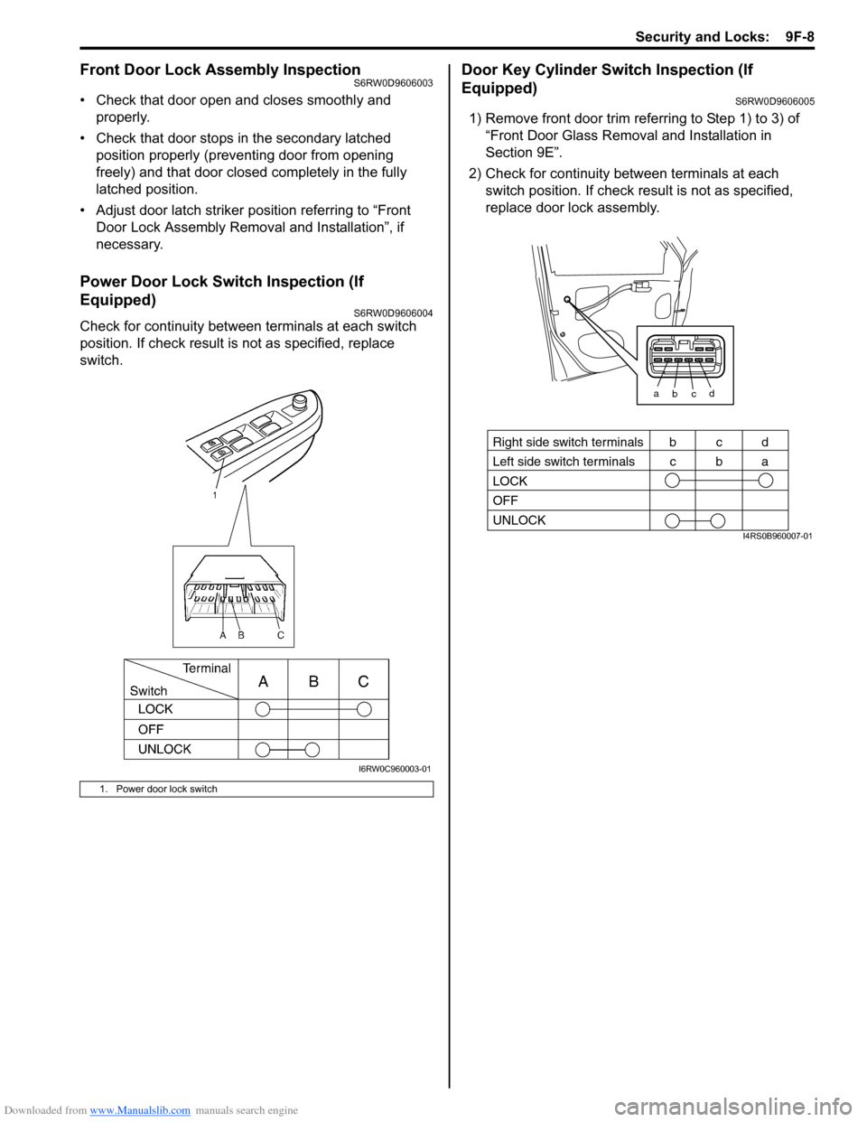
Check for continuity between terminals at each switch
position. If check result is not as specified, replace
switch.
Door Key Cylinder Switch Inspection (If
Equipped)
S6RW0D9606005
1) Remove front door trim referring to Step 1) to 3) of
“Front Door Glass Removal and Installation in
Section 9E”.
2) Check for continuity between terminals at each
switch position. If check result is not as specified,
replace door lock assembly.
1. Power door lock switch
I6RW0C960003-01
a
bc
LOCK
OFF
UNLOCK
bcd
cbaRight side switch terminals
Left side switch terminals
d
I4RS0B960007-01