2006 SUZUKI SX4 indicator
[x] Cancel search: indicatorPage 994 of 1556
![SUZUKI SX4 2006 1.G Service Workshop Manual Downloaded from www.Manualslib.com manuals search engine 7B-54 Air Conditioning System: Automatic Type
DTC of A/C System detected by ECM
NOTE
When no DTC is detected, “FRE” [A] and “REC” [B] i SUZUKI SX4 2006 1.G Service Workshop Manual Downloaded from www.Manualslib.com manuals search engine 7B-54 Air Conditioning System: Automatic Type
DTC of A/C System detected by ECM
NOTE
When no DTC is detected, “FRE” [A] and “REC” [B] i](/manual-img/20/7612/w960_7612-993.png)
Downloaded from www.Manualslib.com manuals search engine 7B-54 Air Conditioning System: Automatic Type
DTC of A/C System detected by ECM
NOTE
When no DTC is detected, “FRE” [A] and “REC” [B] indicator lights on HVAC control module flash at
the same time in specific pattern.
Fail-Safe TableS6RW0D7224007
When any of the following malfunctions (DTCs) is detected, fail-safe mode is activated.
However, when HVAC control module detects normal operation of A/C system, fail-safe mode is canceled. DTC No. Detection itemDetecting condition
(DTC will set when detecting)MIL
P0481 Fan 2 Control Circuit
Refer to “Fail-Safe Table in Section 1A”. P0532A/C Refrigerant Pressure
Sensor Circuit Low
P0533A/C Refrigerant Pressure
Sensor Circuit High
H: ON a. About 3 seconds
L: OFF b. About 1 seconds
DTC No. Trouble AreaFail-Safe Operation
When ignition switch is turned ON
after malfunction is already detectedWhen malfunction is detected during
ignition switch is ON
�) B1502Inside air temperature
sensor circuitHVAC control module maintains last
normal value.HVAC control module controls actuators
assuming that inside air temperature is
25 °C (77 °F).
�) B1503A/C evaporator
temperature sensor
circuitHVAC control module assuming that
evaporator temperature is 0 °C (32 °F).• HVAC control module turns off A/C
switch signal.
• HVAC control module controls
actuators assuming that evaporator
temperature is 0 °C (32 °F).
�) B1504 Sunload sensor circuitHVAC control module maintains last
normal value.HVAC control module controls actuators
assuming that amount of sunlight is 0 W/
m
2.
�) B1520Temperature selector
malfunctionHVAC control module maintains last
normal value.HVAC control module controls actuators
assuming that setting of temperature
selector is 25 °C (77 °F) position.
�) B1521Blower speed selector
malfunctionHVAC control module maintains last
normal value.HVAC control module controls actuators
assuming that setting of blower speed
selector is low (1st) position.
�) B1522Air flow selector
malfunctionHVAC control module maintains last
normal value.HVAC control module controls actuators
assuming that setting of air flow selector
is DEF position.
[A]
[A]H
L
H
L [B]
[B]
baaba
baaba
I5RW0A722008-01
Page 1018 of 1556
Downloaded from www.Manualslib.com manuals search engine 7B-78 Air Conditioning System: Automatic Type
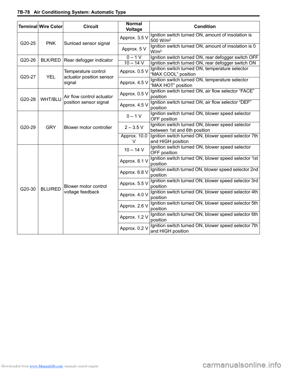
G20-25 PNK Sunload sensor signalApprox. 3.5 VIgnition switch turned ON, amount of insolation is
500 W/m2
Approx. 5 VIgnition switch turned ON, amount of insolation is 0
W/m2
G20-26 BLK/RED Rear defogger indicator0 – 1 V Ignition switch turned ON, rear defogger switch OFF
10 – 14 V Ignition switch turned ON, rear defogger switch ON
G20-27 YELTemperature control
actuator position sensor
signalApprox. 0.5 VIgnition switch turned ON, temperature selector
“MAX COOL” position
Approx. 4.5 VIgnition switch turned ON, temperature selector
“MAX HOT” position
G20-28 WHT/BLUAir flow control actuator
position sensor signalApprox. 0.5 VIgnition switch turned ON, air flow selector “FACE”
position
Approx. 4.5 VIgnition switch turned ON, air flow selector “DEF”
position
G20-29 GRY Blower motor controller0 – 1 VIgnition switch turned ON, blower speed selector
OFF position
2 – 3.5 VIgnition switch turned ON, blower speed selector
between 1st and 6th position
Approx. 10.0
VIgnition switch turned ON, blower speed selector 7th
and HIGH position
G20-30 BLU/REDBlower motor control
voltage feedback10 – 14 VIgnition switch turned ON, blower speed selector
OFF position
Approx. 8.1 VIgnition switch turned ON, blower speed selector 1st
position
Approx. 6.8 VIgnition switch turned ON, blower speed selector 2nd
position
Approx. 5.5 VIgnition switch turned ON, blower speed selector 3rd
position
Approx. 4.0 VIgnition switch turned ON, blower speed selector 4th
position
Approx. 2.6 VIgnition switch turned ON, blower speed selector 5th
position
Approx. 1.2 VIgnition switch turned ON, blower speed selector 6th
position
Approx. 0.2 VIgnition switch turned ON, blower speed selector 7th
and HIGH position Terminal Wire Color CircuitNormal
Vo l ta g eCondition
Page 1061 of 1556
Downloaded from www.Manualslib.com manuals search engine Air Bag System: 8B-22
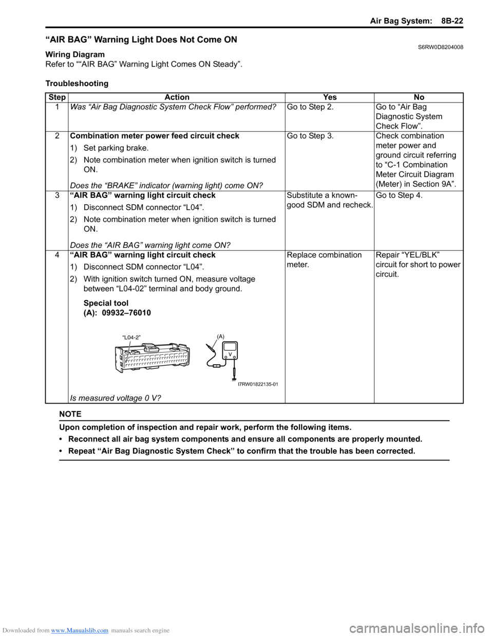
“AIR BAG” Warning Light Does Not Come ONS6RW0D8204008
Wiring Diagram
Refer to ““AIR BAG” Warning Light Comes ON Steady”.
Troubleshooting
NOTE
Upon completion of inspection and repair work, perform the following items.
• Reconnect all air bag system components and ensure all components are properly mounted.
• Repeat “Air Bag Diagnostic System Check” to confirm that the trouble has been corrected.
Step Action Yes No
1Was “Air Bag Diagnostic System Check Flow” performed?Go to Step 2. Go to “Air Bag
Diagnostic System
Check Flow”.
2Combination meter power feed circuit check
1) Set parking brake.
2) Note combination meter when ignition switch is turned
ON.
Does the “BRAKE” indicator (warning light) come ON?Go to Step 3. Check combination
meter power and
ground circuit referring
to “C-1 Combination
Meter Circuit Diagram
(Meter) in Section 9A”.
3“AIR BAG” warning light circuit check
1) Disconnect SDM connector “L04”.
2) Note combination meter when ignition switch is turned
ON.
Does the “AIR BAG” warning light come ON?Substitute a known-
good SDM and recheck.Go to Step 4.
4“AIR BAG” warning light circuit check
1) Disconnect SDM connector “L04”.
2) With ignition switch turned ON, measure voltage
between “L04-02” terminal and body ground.
Special tool
(A): 09932–76010
Is measured voltage 0 V?Replace combination
meter.Repair “YEL/BLK”
circuit for short to power
circuit.
(A)“L04-2”
I7RW01822135-01
Page 1162 of 1556
Downloaded from www.Manualslib.com manuals search engine 9-ii Table of Contents
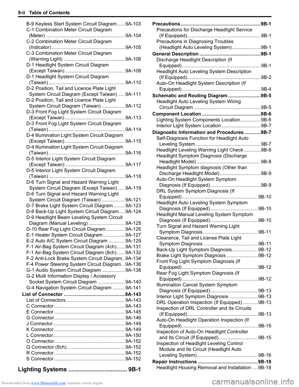
B-9 Keyless Start System Circuit Diagram...... 9A-103
C-1 Combination Meter Circuit Diagram
(Meter) .......................................................... 9A-104
C-2 Combination Meter Circuit Diagram
(Indicator) ...................................................... 9A-105
C-3 Combination Meter Circuit Diagram
(Warning Light) ............................................. 9A-106
D-1 Headlight System Circuit Diagram
(Except Taiwan) ............................................ 9A-108
D-1 Headlight System Circuit Diagram
(Taiwan) ........................................................ 9A-110
D-2 Position, Tail and Licence Plate Light
System Circuit Diagram (Except Taiwan) ..... 9A-111
D-2 Position, Tail and Licence Plate Light
System Circuit Diagram (Taiwan) ................. 9A-112
D-3 Front Fog Light System Circuit Diagram
(Except Taiwan) ............................................ 9A-113
D-3 Front Fog Light System Circuit Diagram
(Taiwan) ........................................................ 9A-114
D-4 Illumination Light System Circuit Diagram
(Except Taiwan) ............................................ 9A-115
D-4 Illumination Light System Circuit Diagram
(Taiwan) ........................................................ 9A-116
D-5 Interior Light System Circuit Diagram
(Except Taiwan) ............................................ 9A-117
D-5 Interior Light System Circuit Diagram
(Taiwan) ........................................................ 9A-118
D-6 Turn Signal and Hazard Warning Light
System Circuit Diagram (Except Taiwan) ..... 9A-119
D-6 Turn Signal and Hazard Warning Light
System Circuit Diagram (Taiwan) ................. 9A-121
D-7 Brake Light System Circuit Diagram ........ 9A-123
D-8 Back-Up Light System Circuit Diagram .... 9A-124
D-9 Headlight Beam Leveling System Circuit
Diagram (Manual Leveling)........................... 9A-125
D-10 Rear Fog Light Circuit Diagram .............. 9A-126
E-1 Heater System Circuit Diagram ................ 9A-127
E-2 Auto A/C System Circuit Diagram ............ 9A-129
F-1 Air-Bag System Circuit Diagram (4ch) ...... 9A-131
F-1 Air-Bag System Circuit Diagram (8ch) ...... 9A-132
F-2 Anti-Lock Brake System Circuit Diagram.. 9A-134
F-4 Power Steering System Circuit Diagram .. 9A-136
G-1 Audio System Circuit Diagram ................. 9A-138
G-2 Multi Information Display / Accessory
Socket System Circuit Diagram .................... 9A-140
G-4 Navigation System Circuit Diagram ......... 9A-141
List of Connector .............................................9A-143
List of Connectors ........................................... 9A-143
C Connector .................................................... 9A-143
E Connector .................................................... 9A-145
G Connector .................................................... 9A-146
J Connector ..................................................... 9A-149
K Connector .................................................... 9A-149
L Connector..................................................... 9A-150
O Connector .................................................... 9A-152
Q Connector (8ch)........................................... 9A-152
R Connector .................................................... 9A-152
S Connector .................................................... 9A-152
Lighting Systems .................................... 9B-1
Precautions ...........................................................9B-1
Precautions for Discharge Headlight Service
(If Equipped)...................................................... 9B-1
Precautions in Diagnosing Troubles
(Headlight Auto Leveling System) ..................... 9B-1
General Description .............................................9B-1
Discharge Headlight Description (If
Equipped) .......................................................... 9B-1
Headlight Auto Leveling System Description
(If Equipped)...................................................... 9B-2
Auto-On Headlight System Description (If
Equipped) .......................................................... 9B-4
Schematic and Routing Diagram ........................9B-5
Headlight Auto Leveling System Wiring
Circuit Diagram ................................................. 9B-5
Component Location ...........................................9B-6
Lighting System Components Location............... 9B-6
Interior Light System Location............................. 9B-7
Diagnostic Information and Procedures ............9B-7
Self-Diagnosis Function for Headlight Auto
Leveling System ................................................ 9B-7
Headlight Leveling Warning Light Check ............ 9B-8
Headlight Symptom Diagnosis (Discharge
Headlight Model) ............................................... 9B-8
Headlight Symptom diagnosis (Other than
Discharge Headlight Model) .............................. 9B-9
Auto-On Headlight System Symptom
Diagnosis (If Equipped) ..................................... 9B-9
DRL System Symptom Diagnosis (If
Equipped) ........................................................ 9B-10
Headlight Auto Leveling System Symptom
Diagnosis (If Equipped) ................................... 9B-10
Headlight Manual Leveling System Symptom
Diagnosis (If Equipped) ................................... 9B-10
Turn Signal and Hazard Warning Light
Symptom Diagnosis ........................................ 9B-11
Clearance, Tail and License Plate Light
Symptom Diagnosis ........................................ 9B-11
Back-Up Light Symptom Diagnosis................... 9B-12
Brake Light Symptom Diagnosis ....................... 9B-12
Front Fog Light Symptom Diagnosis (If
Equipped) ........................................................ 9B-12
Rear Fog Light Symptom Diagnosis (If
Equipped) ........................................................ 9B-12
Illumination Cancel System Symptom
Diagnosis (If Equipped) ................................... 9B-13
Interior Light Symptom Diagnosis ..................... 9B-13
DRL Operation Inspection (If Equipped) ........... 9B-13
Inspection of DRL Controller and Its Circuits
(If Equipped).................................................... 9B-13
Auto-On Headlight Operation Inspection (If
Equipped) ........................................................ 9B-15
Inspection of Auto-On Headlight Controller
and Its Circuit (If Equipped)............................. 9B-15
Inspection of Headlight Leveling Control
Module and Its Circuit (Headlight Auto
Leveling System)............................................. 9B-16
Repair Instructions ............................................9B-18
Headlight Housing Removal and Installation .... 9B-18
Page 1163 of 1556
Downloaded from www.Manualslib.com manuals search engine Table of Contents 9-iii
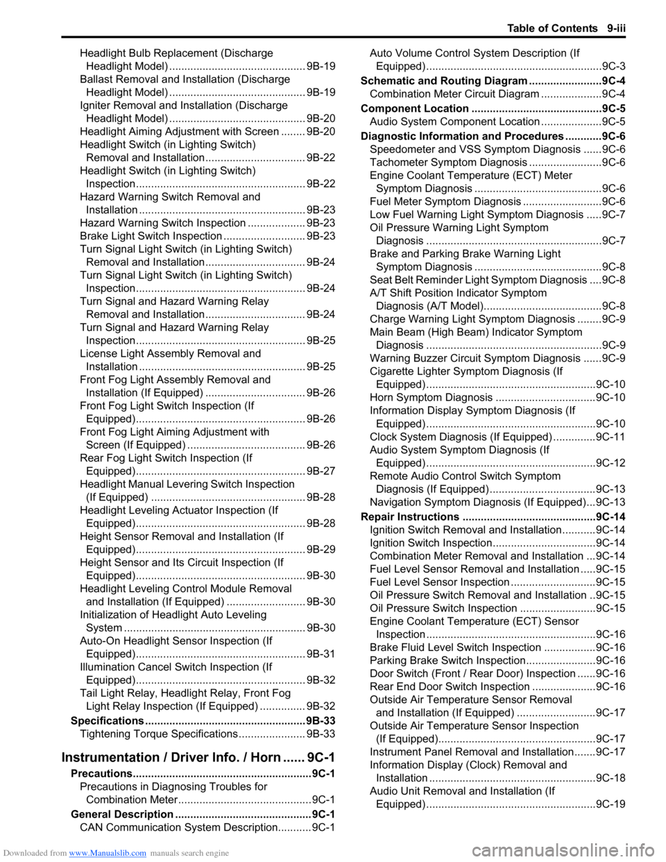
Headlight Bulb Replacement (Discharge
Headlight Model) ............................................. 9B-19
Ballast Removal and Installation (Discharge
Headlight Model) ............................................. 9B-19
Igniter Removal and Installation (Discharge
Headlight Model) ............................................. 9B-20
Headlight Aiming Adjustment with Screen ........ 9B-20
Headlight Switch (in Lighting Switch)
Removal and Installation................................. 9B-22
Headlight Switch (in Lighting Switch)
Inspection........................................................ 9B-22
Hazard Warning Switch Removal and
Installation ....................................................... 9B-23
Hazard Warning Switch Inspection ................... 9B-23
Brake Light Switch Inspection ........................... 9B-23
Turn Signal Light Switch (in Lighting Switch)
Removal and Installation................................. 9B-24
Turn Signal Light Switch (in Lighting Switch)
Inspection........................................................ 9B-24
Turn Signal and Hazard Warning Relay
Removal and Installation................................. 9B-24
Turn Signal and Hazard Warning Relay
Inspection........................................................ 9B-25
License Light Assembly Removal and
Installation ....................................................... 9B-25
Front Fog Light Assembly Removal and
Installation (If Equipped) ................................. 9B-26
Front Fog Light Switch Inspection (If
Equipped)........................................................ 9B-26
Front Fog Light Aiming Adjustment with
Screen (If Equipped) ....................................... 9B-26
Rear Fog Light Switch Inspection (If
Equipped)........................................................ 9B-27
Headlight Manual Levering Switch Inspection
(If Equipped) ................................................... 9B-28
Headlight Leveling Actuator Inspection (If
Equipped)........................................................ 9B-28
Height Sensor Removal and Installation (If
Equipped)........................................................ 9B-29
Height Sensor and Its Circuit Inspection (If
Equipped)........................................................ 9B-30
Headlight Leveling Control Module Removal
and Installation (If Equipped) .......................... 9B-30
Initialization of Headlight Auto Leveling
System ............................................................ 9B-30
Auto-On Headlight Sensor Inspection (If
Equipped)........................................................ 9B-31
Illumination Cancel Switch Inspection (If
Equipped)........................................................ 9B-32
Tail Light Relay, Headlight Relay, Front Fog
Light Relay Inspection (If Equipped) ............... 9B-32
Specifications..................................................... 9B-33
Tightening Torque Specifications ...................... 9B-33
Instrumentation / Driver Info. / Horn ...... 9C-1
Precautions........................................................... 9C-1
Precautions in Diagnosing Troubles for
Combination Meter............................................ 9C-1
General Description ............................................. 9C-1
CAN Communication System Description........... 9C-1Auto Volume Control System Description (If
Equipped) ..........................................................9C-3
Schematic and Routing Diagram ........................9C-4
Combination Meter Circuit Diagram ....................9C-4
Component Location ...........................................9C-5
Audio System Component Location ....................9C-5
Diagnostic Information and Procedures ............9C-6
Speedometer and VSS Symptom Diagnosis ......9C-6
Tachometer Symptom Diagnosis ........................9C-6
Engine Coolant Temperature (ECT) Meter
Symptom Diagnosis ..........................................9C-6
Fuel Meter Symptom Diagnosis ..........................9C-6
Low Fuel Warning Light Symptom Diagnosis .....9C-7
Oil Pressure Warning Light Symptom
Diagnosis ..........................................................9C-7
Brake and Parking Brake Warning Light
Symptom Diagnosis ..........................................9C-8
Seat Belt Reminder Light Symptom Diagnosis ....9C-8
A/T Shift Position Indicator Symptom
Diagnosis (A/T Model).......................................9C-8
Charge Warning Light Symptom Diagnosis ........9C-9
Main Beam (High Beam) Indicator Symptom
Diagnosis ..........................................................9C-9
Warning Buzzer Circuit Symptom Diagnosis ......9C-9
Cigarette Lighter Symptom Diagnosis (If
Equipped) ........................................................9C-10
Horn Symptom Diagnosis .................................9C-10
Information Display Symptom Diagnosis (If
Equipped) ........................................................9C-10
Clock System Diagnosis (If Equipped) ..............9C-11
Audio System Symptom Diagnosis (If
Equipped) ........................................................9C-12
Remote Audio Control Switch Symptom
Diagnosis (If Equipped) ...................................9C-13
Navigation Symptom Diagnosis (If Equipped)...9C-13
Repair Instructions ............................................9C-14
Ignition Switch Removal and Installation...........9C-14
Ignition Switch Inspection..................................9C-14
Combination Meter Removal and Installation ...9C-14
Fuel Level Sensor Removal and Installation .....9C-15
Fuel Level Sensor Inspection ............................9C-15
Oil Pressure Switch Removal and Installation ..9C-15
Oil Pressure Switch Inspection .........................9C-15
Engine Coolant Temperature (ECT) Sensor
Inspection ........................................................9C-16
Brake Fluid Level Switch Inspection .................9C-16
Parking Brake Switch Inspection.......................9C-16
Door Switch (Front / Rear Door) Inspection ......9C-16
Rear End Door Switch Inspection .....................9C-16
Outside Air Temperature Sensor Removal
and Installation (If Equipped) ..........................9C-17
Outside Air Temperature Sensor Inspection
(If Equipped)....................................................9C-17
Instrument Panel Removal and Installation.......9C-17
Information Display (Clock) Removal and
Installation .......................................................9C-18
Audio Unit Removal and Installation (If
Equipped) ........................................................9C-19
Page 1168 of 1556
Downloaded from www.Manualslib.com manuals search engine 9A-1 Wiring Systems:
Body, Cab and Accessories
Wiring Systems
Precautions
Cautions in Body Electrical System ServicingS6RW0D9100001
When servicing the electric systems, observe the cautions described in “Air Bag Warning in Section 00” to protect
electrical parts and to prevent a fire.
General Description
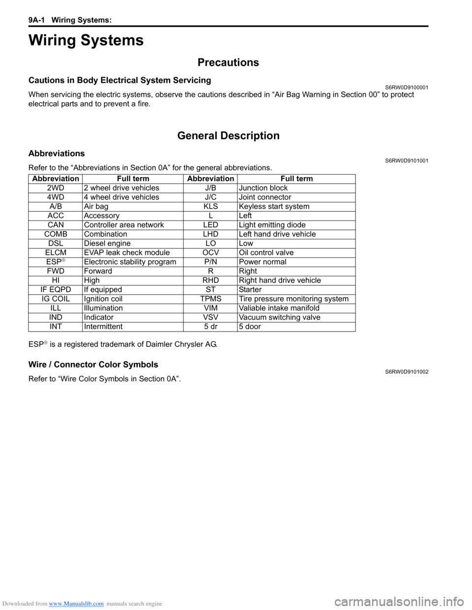
AbbreviationsS6RW0D9101001
Refer to the “Abbreviations in Section 0A” for the general abbreviations.
ESP
® is a registered trademark of Daimler Chrysler AG.
Wire / Connector Color SymbolsS6RW0D9101002
Refer to “Wire Color Symbols in Section 0A”. Abbreviation Full term Abbreviation Full term
2WD 2 wheel drive vehicles J/B Junction block
4WD 4 wheel drive vehicles J/C Joint connector
A/B Air bag KLS Keyless start system
ACC Accessory L Left
CAN Controller area network LED Light emitting diode
COMB Combination LHD Left hand drive vehicle
DSL Diesel engine LO Low
ELCM EVAP leak check module OCV Oil control valve
ESP
®Electronic stability program P/N Power normal
FWD Forward R Right
HI High RHD Right hand drive vehicle
IF EQPD If equipped ST Starter
IG COIL Ignition coil TPMS Tire pressure monitoring system
ILL Illumination VIM Valiable intake manifold
IND Indicator VSV Vacuum switching valve
INT Intermittent 5 dr 5 door
Page 1224 of 1556
Downloaded from www.Manualslib.com manuals search engine 9A-57 Wiring Systems:
System Circuit Diagram
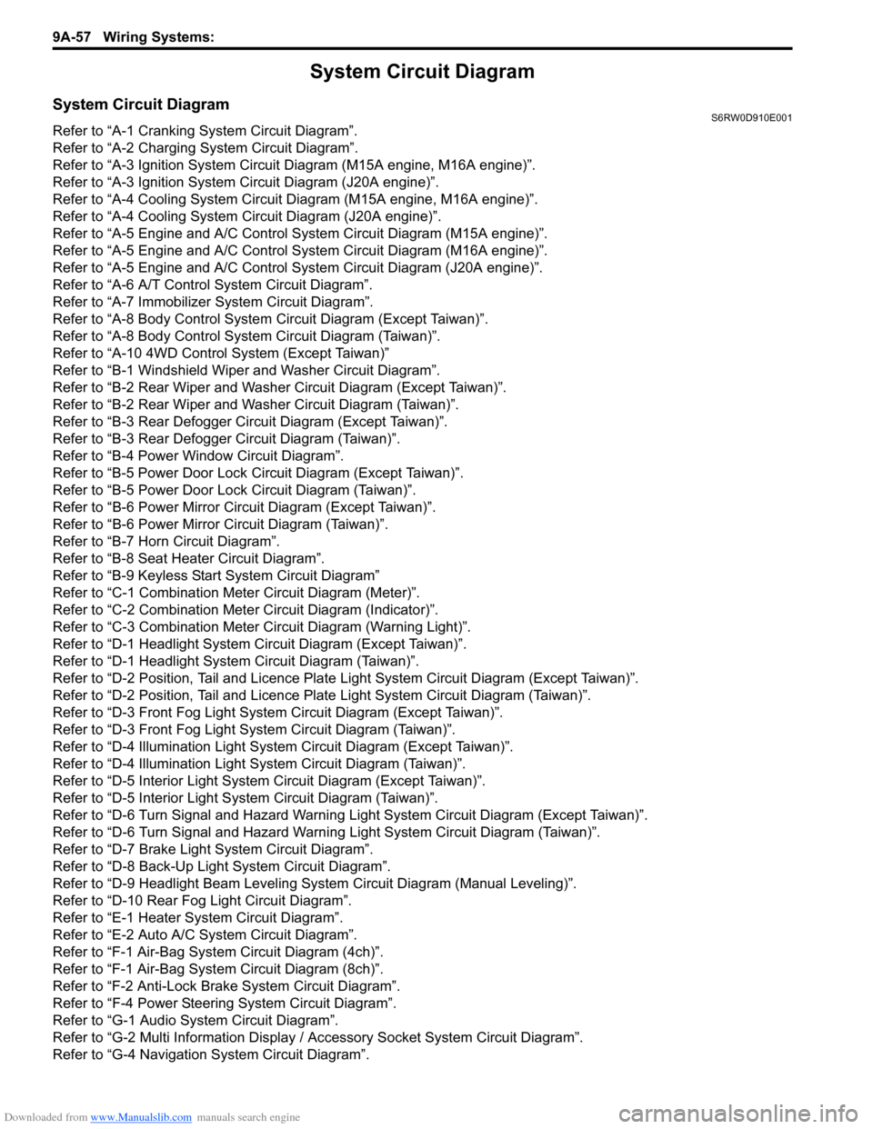
System Circuit DiagramS6RW0D910E001
Refer to “A-1 Cranking System Circuit Diagram”.
Refer to “A-2 Charging System Circuit Diagram”.
Refer to “A-3 Ignition System Circuit Diagram (M15A engine, M16A engine)”.
Refer to “A-3 Ignition System Circuit Diagram (J20A engine)”.
Refer to “A-4 Cooling System Circuit Diagram (M15A engine, M16A engine)”.
Refer to “A-4 Cooling System Circuit Diagram (J20A engine)”.
Refer to “A-5 Engine and A/C Control System Circuit Diagram (M15A engine)”.
Refer to “A-5 Engine and A/C Control System Circuit Diagram (M16A engine)”.
Refer to “A-5 Engine and A/C Control System Circuit Diagram (J20A engine)”.
Refer to “A-6 A/T Control System Circuit Diagram”.
Refer to “A-7 Immobilizer System Circuit Diagram”.
Refer to “A-8 Body Control System Circuit Diagram (Except Taiwan)”.
Refer to “A-8 Body Control System Circuit Diagram (Taiwan)”.
Refer to “A-10 4WD Control System (Except Taiwan)”
Refer to “B-1 Windshield Wiper and Washer Circuit Diagram”.
Refer to “B-2 Rear Wiper and Washer Circuit Diagram (Except Taiwan)”.
Refer to “B-2 Rear Wiper and Washer Circuit Diagram (Taiwan)”.
Refer to “B-3 Rear Defogger Circuit Diagram (Except Taiwan)”.
Refer to “B-3 Rear Defogger Circuit Diagram (Taiwan)”.
Refer to “B-4 Power Window Circuit Diagram”.
Refer to “B-5 Power Door Lock Circuit Diagram (Except Taiwan)”.
Refer to “B-5 Power Door Lock Circuit Diagram (Taiwan)”.
Refer to “B-6 Power Mirror Circuit Diagram (Except Taiwan)”.
Refer to “B-6 Power Mirror Circuit Diagram (Taiwan)”.
Refer to “B-7 Horn Circuit Diagram”.
Refer to “B-8 Seat Heater Circuit Diagram”.
Refer to “B-9 Keyless Start System Circuit Diagram”
Refer to “C-1 Combination Meter Circuit Diagram (Meter)”.
Refer to “C-2 Combination Meter Circuit Diagram (Indicator)”.
Refer to “C-3 Combination Meter Circuit Diagram (Warning Light)”.
Refer to “D-1 Headlight System Circuit Diagram (Except Taiwan)”.
Refer to “D-1 Headlight System Circuit Diagram (Taiwan)”.
Refer to “D-2 Position, Tail and Licence Plate Light System Circuit Diagram (Except Taiwan)”.
Refer to “D-2 Position, Tail and Licence Plate Light System Circuit Diagram (Taiwan)”.
Refer to “D-3 Front Fog Light System Circuit Diagram (Except Taiwan)”.
Refer to “D-3 Front Fog Light System Circuit Diagram (Taiwan)”.
Refer to “D-4 Illumination Light System Circuit Diagram (Except Taiwan)”.
Refer to “D-4 Illumination Light System Circuit Diagram (Taiwan)”.
Refer to “D-5 Interior Light System Circuit Diagram (Except Taiwan)”.
Refer to “D-5 Interior Light System Circuit Diagram (Taiwan)”.
Refer to “D-6 Turn Signal and Hazard Warning Light System Circuit Diagram (Except Taiwan)”.
Refer to “D-6 Turn Signal and Hazard Warning Light System Circuit Diagram (Taiwan)”.
Refer to “D-7 Brake Light System Circuit Diagram”.
Refer to “D-8 Back-Up Light System Circuit Diagram”.
Refer to “D-9 Headlight Beam Leveling System Circuit Diagram (Manual Leveling)”.
Refer to “D-10 Rear Fog Light Circuit Diagram”.
Refer to “E-1 Heater System Circuit Diagram”.
Refer to “E-2 Auto A/C System Circuit Diagram”.
Refer to “F-1 Air-Bag System Circuit Diagram (4ch)”.
Refer to “F-1 Air-Bag System Circuit Diagram (8ch)”.
Refer to “F-2 Anti-Lock Brake System Circuit Diagram”.
Refer to “F-4 Power Steering System Circuit Diagram”.
Refer to “G-1 Audio System Circuit Diagram”.
Refer to “G-2 Multi Information Display / Accessory Socket System Circuit Diagram”.
Refer to “G-4 Navigation System Circuit Diagram”.
Page 1272 of 1556
Downloaded from www.Manualslib.com manuals search engine 9A-105 Wiring Systems:
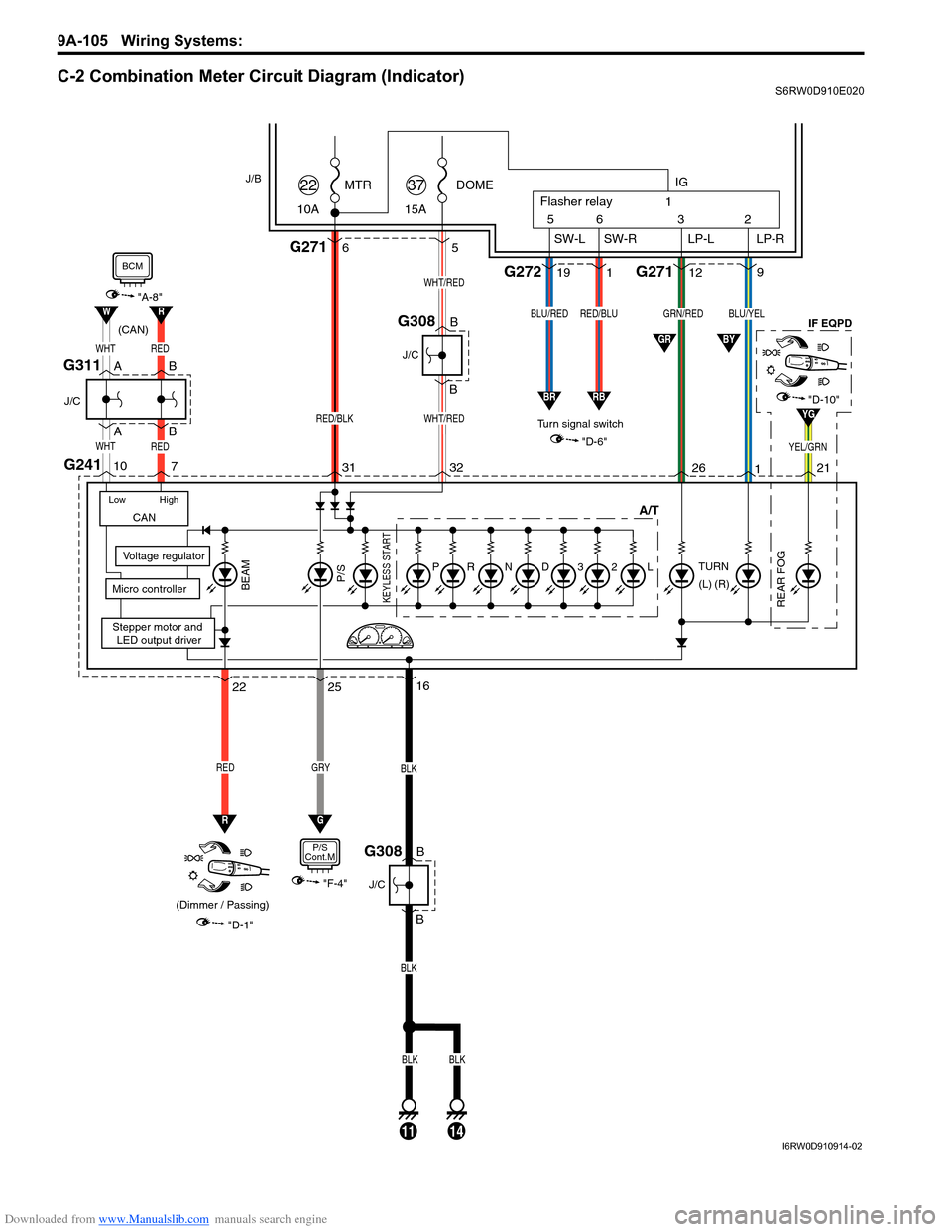
C-2 Combination Meter Circuit Diagram (Indicator)S6RW0D910E020
DOME
15A37MTR
10A22
WHT/RED
WHT/RED
32 315
Stepper motor and
LED output driver
Voltage regulator
Micro controllerKEYLESS START
G2716
RED/BLK
"D-1"
BEAM
22
RED
(Dimmer / Passing)
J/B
16
B
B
BLK
BLK
J/C
G308
11
CAN
Low High
B
B
J/C
G308
R
25
GRY
G
G241
WHTRED
WHTRED
"A-8"RW
10
7
"D-10"YG
BCM
"F-4"
P/S
Cont.M
26 211
"D-6"
TURN
REAR FOG
IF EQPD
(R)GRN/REDBLU/YEL
YEL/GRN
912
3 56
SW-L SW-R LP-LIG
LP-R Flasher relay
2 1
119G272 G271
Turn signal switch
RED/BLUBLU/RED
GR
RBBR
(L)
BY(CAN)
BLKBLK
14
A/T
L23DNRPP/S
A
A
J/C
B
BG311
I6RW0D910914-02