2006 SUZUKI SX4 indicator
[x] Cancel search: indicatorPage 1509 of 1556
Downloaded from www.Manualslib.com manuals search engine Immobilizer Control System: 10C-7
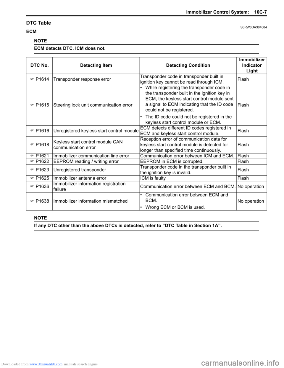
DTC TableS6RW0DA304004
ECM
NOTE
ECM detects DTC. ICM does not.
NOTE
If any DTC other than the above DTCs is detected, refer to “DTC Table in Section 1A”.
DTC No. Detecting Item Detecting ConditionImmobilizer
Indicator
Light
�) P1614 Transponder response errorTransponder code in transponder built in
ignition key cannot be read through ICM.Flash
�) P1615 Steering lock unit communication error• While registering the transponder code in
the transponder built in the ignition key in
ECM, the keyless start control module sent
a signal to ECM indicating that the ID code
could not be registered.
• The ID code could not be registered in the
keyless start control module or ECM.Flash
�) P1616 Unregistered keyless start control moduleECM detects different ID codes registered in
ECM and keyless start control module.Flash
�) P1618Keyless start control module CAN
communication errorReception error of communication data for
keyless start control module is detected for
longer than specified time continuously.Flash
�) P1621 Immobilizer communication line error Communication error between ICM and ECM. Flash
�) P1622 EEPROM reading / writing error EEPROM in ECM is corrupted. Flash
�) P1623 Unregistered transponderTransponder code in the transponder built in
the ignition key is invalid.Flash
�) P1625 Immobilizer antenna error ICM is faulty. Flash
�) P1636Immobilizer information registration
failureCommunication error between ECM and BCM. No operation
�) P1638 Immobilizer information mismatched• Communication error between ECM and
BCM.
• Wrong ECM or BCM is used.No operation
Page 1511 of 1556
Downloaded from www.Manualslib.com manuals search engine Immobilizer Control System: 10C-9
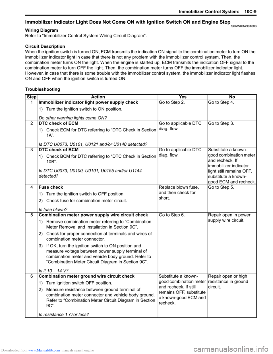
Immobilizer Indicator Light Does Not Come ON with Ignition Switch ON and Engine StopS6RW0DA304006
Wiring Diagram
Refer to “Immobilizer Control System Wiring Circuit Diagram”.
Circuit Description
When the ignition switch is turned ON, ECM transmits the indication ON signal to the combination meter to turn ON the
immobilizer indicator light in case that there is not any problem with the immobilizer control system. Then, the
combination meter turns ON the light. When the engine is started up, ECM transmits the indication OFF signal to the
combination meter to turn OFF the light. Then, the combination meter turns OFF the immobilizer indicator light.
However, in case that there is some trouble with the immobilizer control system, the immobilizer indicator light flashes
ON and OFF when the ignition switch is turned ON.
Troubleshooting
Step Action Yes No
1Immobilizer indicator light power supply check
1) Turn the ignition switch to ON position.
Do other warning lights come ON?Go to Step 2. Go to Step 4.
2DTC check of ECM
1) Check ECM for DTC referring to “DTC Check in Section
1A”.
Is DTC U0073, U0101, U0121 and/or U0140 detected?Go to applicable DTC
diag. flow.Go to Step 3.
3DTC check of BCM
1) Check BCM for DTC referring to “DTC Check in Section
10B”.
Is DTC U0073, U0100, U0101, U0155 and/or U1144
detected?Go to applicable DTC
diag. flow.Substitute a known-
good combination meter
and recheck. If
immobilizer indicator
light still remains OFF,
substitute a known-
good ECM and recheck.
4Fuse check
1) Turn the ignition switch to OFF position.
2) Check fuse for combination meter circuit.
Is fuse blown?Replace blown fuse,
and then check for
short.Go to Step 5.
5Combination meter power supply wire circuit check
1) Remove combination meter referring to “Combination
Meter Removal and Installation in Section 9C”.
2) Check for proper connection at terminals and wires of
combination meter connector.
3) If OK, turn the ignition switch to ON position and
measure voltage between power supply terminal of
combination meter and vehicle body ground. Refer to
“Combination Meter Circuit Diagram in Section 9C”.
Is it 10 – 14 V?Go to Step 6. Repair open in power
supply wire circuit.
6Combination meter ground wire circuit check
1) Turn ignition switch OFF position.
2) Measure resistance between ground terminal of
combination meter connector and vehicle body ground.
Refer to “Combination Meter Circuit Diagram in Section
9C”.
Is resistance 1
Ω or less?Substitute a known-
good combination meter
and recheck. If still
remains OFF, substitute
a known-good ECM and
recheck.Repair open or high
resistance in ground
circuit.
Page 1512 of 1556
Downloaded from www.Manualslib.com manuals search engine 10C-10 Immobilizer Control System:
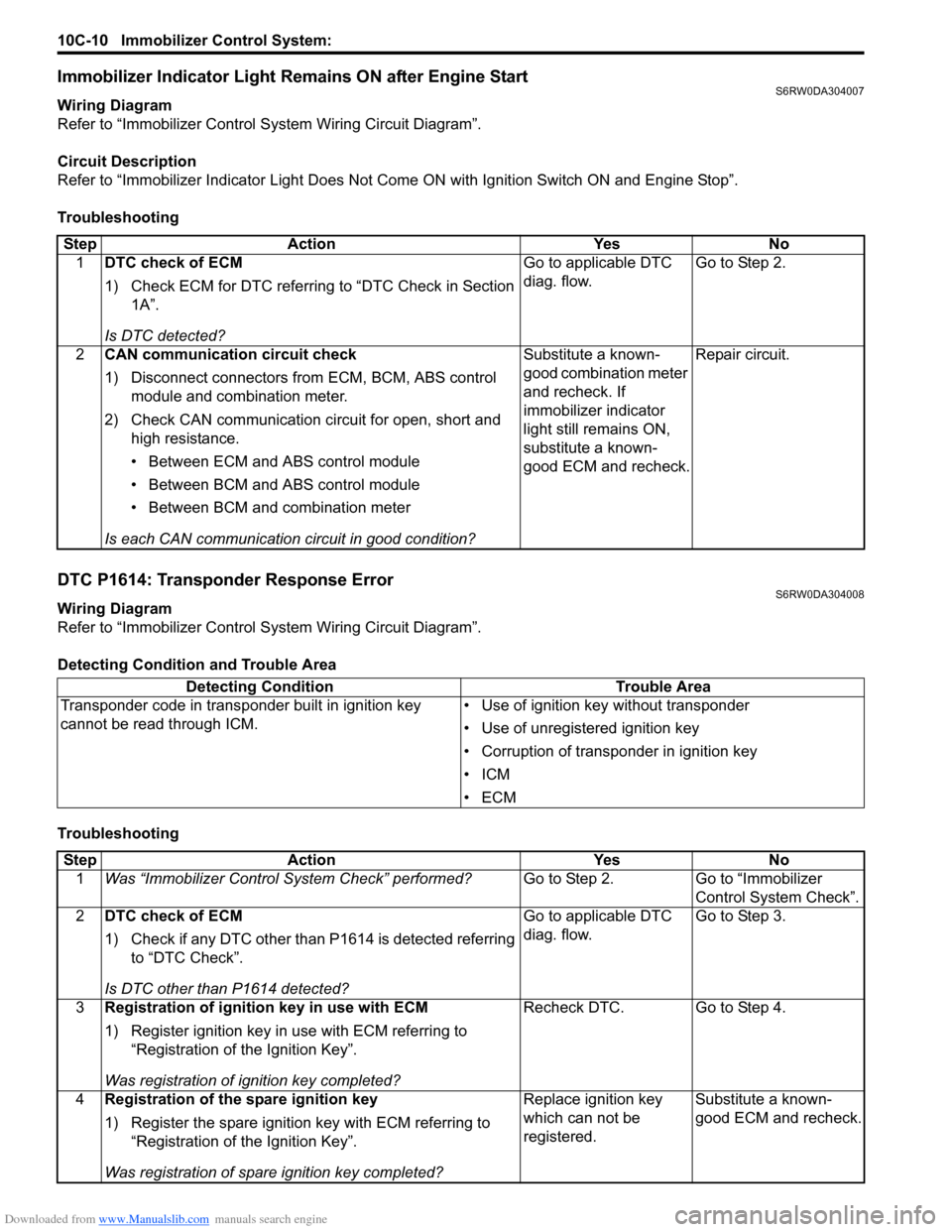
Immobilizer Indicator Light Remains ON after Engine StartS6RW0DA304007
Wiring Diagram
Refer to “Immobilizer Control System Wiring Circuit Diagram”.
Circuit Description
Refer to “Immobilizer Indicator Light Does Not Come ON with Ignition Switch ON and Engine Stop”.
Troubleshooting
DTC P1614: Transponder Response ErrorS6RW0DA304008
Wiring Diagram
Refer to “Immobilizer Control System Wiring Circuit Diagram”.
Detecting Condition and Trouble Area
TroubleshootingStep Action Yes No
1DTC check of ECM
1) Check ECM for DTC referring to “DTC Check in Section
1A”.
Is DTC detected?Go to applicable DTC
diag. flow.Go to Step 2.
2CAN communication circuit check
1) Disconnect connectors from ECM, BCM, ABS control
module and combination meter.
2) Check CAN communication circuit for open, short and
high resistance.
• Between ECM and ABS control module
• Between BCM and ABS control module
• Between BCM and combination meter
Is each CAN communication circuit in good condition?Substitute a known-
good combination meter
and recheck. If
immobilizer indicator
light still remains ON,
substitute a known-
good ECM and recheck.Repair circuit.
Detecting Condition Trouble Area
Transponder code in transponder built in ignition key
cannot be read through ICM.• Use of ignition key without transponder
• Use of unregistered ignition key
• Corruption of transponder in ignition key
•ICM
•ECM
Step Action Yes No
1Was “Immobilizer Control System Check” performed?Go to Step 2. Go to “Immobilizer
Control System Check”.
2DTC check of ECM
1) Check if any DTC other than P1614 is detected referring
to “DTC Check”.
Is DTC other than P1614 detected?Go to applicable DTC
diag. flow.Go to Step 3.
3Registration of ignition key in use with ECM
1) Register ignition key in use with ECM referring to
“Registration of the Ignition Key”.
Was registration of ignition key completed?Recheck DTC. Go to Step 4.
4Registration of the spare ignition key
1) Register the spare ignition key with ECM referring to
“Registration of the Ignition Key”.
Was registration of spare ignition key completed?Replace ignition key
which can not be
registered.Substitute a known-
good ECM and recheck.
Page 1523 of 1556
Downloaded from www.Manualslib.com manuals search engine Keyless Start System: 10E-1
Control Systems
Keyless Start System
General Description
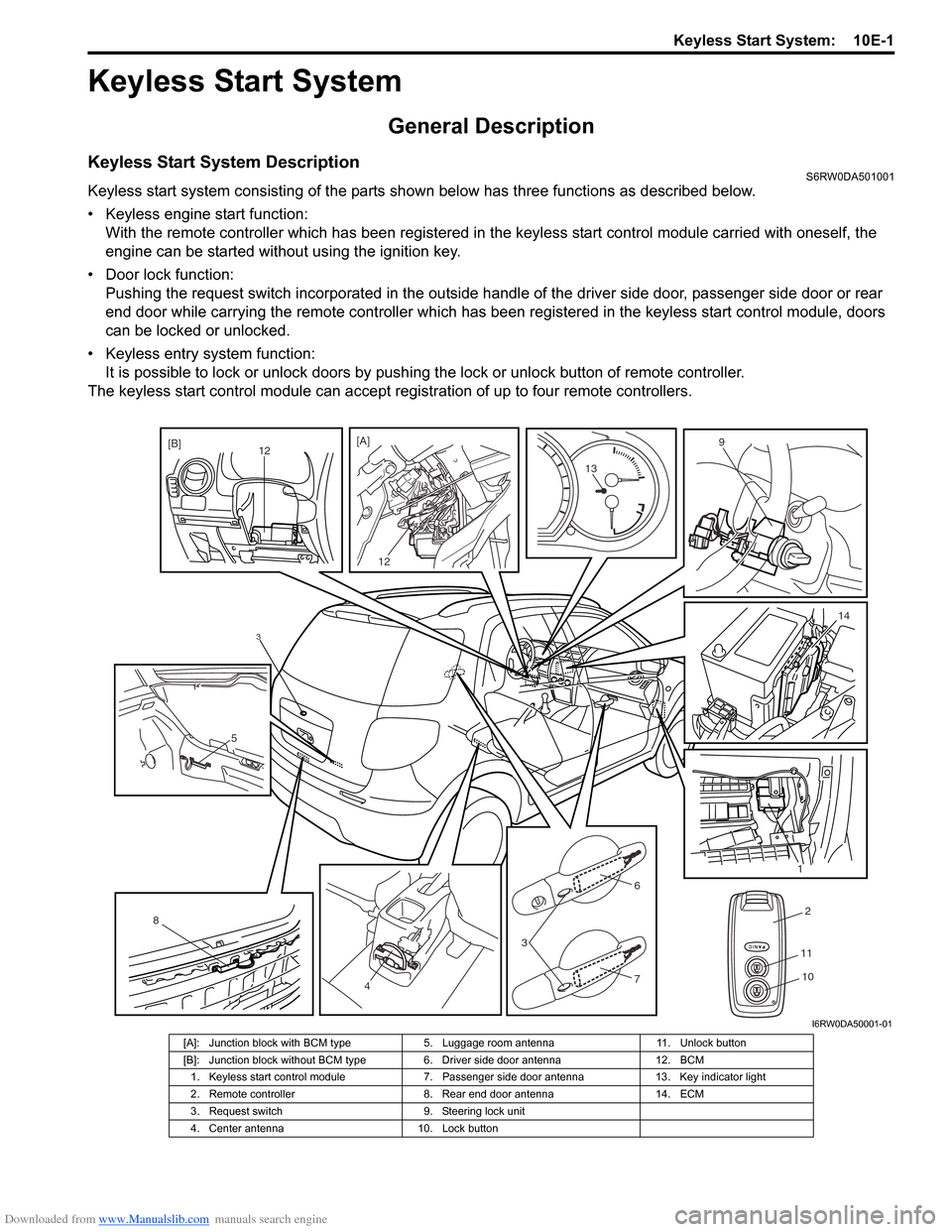
Keyless Start System DescriptionS6RW0DA501001
Keyless start system consisting of the parts shown below has three functions as described below.
• Keyless engine start function:
With the remote controller which has been registered in the keyless start control module carried with oneself, the
engine can be started without using the ignition key.
• Door lock function:
Pushing the request switch incorporated in the outside handle of the driver side door, passenger side door or rear
end door while carrying the remote controller which has been registered in the keyless start control module, doors
can be locked or unlocked.
• Keyless entry system function:
It is possible to lock or unlock doors by pushing the lock or unlock button of remote controller.
The keyless start control module can accept registration of up to four remote controllers.
3
2
11
104
8
5
3
6
7
1
14
13
9
12 [A]
12[B]
I6RW0DA50001-01
[A]: Junction block with BCM type 5. Luggage room antenna 11. Unlock button
[B]: Junction block without BCM type 6. Driver side door antenna 12. BCM
1. Keyless start control module 7. Passenger side door antenna 13. Key indicator light
2. Remote controller 8. Rear end door antenna 14. ECM
3. Request switch 9. Steering lock unit
4. Center antenna 10. Lock button
Page 1524 of 1556
Downloaded from www.Manualslib.com manuals search engine 10E-2 Keyless Start System:
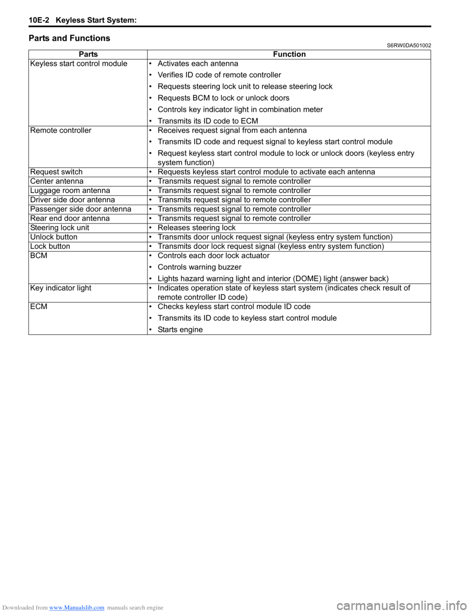
Parts and FunctionsS6RW0DA501002
Parts Function
Keyless start control module • Activates each antenna
• Verifies ID code of remote controller
• Requests steering lock unit to release steering lock
• Requests BCM to lock or unlock doors
• Controls key indicator light in combination meter
• Transmits its ID code to ECM
Remote controller • Receives request signal from each antenna
• Transmits ID code and request signal to keyless start control module
• Request keyless start control module to lock or unlock doors (keyless entry
system function)
Request switch • Requests keyless start control module to activate each antenna
Center antenna • Transmits request signal to remote controller
Luggage room antenna • Transmits request signal to remote controller
Driver side door antenna • Transmits request signal to remote controller
Passenger side door antenna • Transmits request signal to remote controller
Rear end door antenna • Transmits request signal to remote controller
Steering lock unit • Releases steering lock
Unlock button • Transmits door unlock request signal (keyless entry system function)
Lock button • Transmits door lock request signal (keyless entry system function)
BCM • Controls each door lock actuator
• Controls warning buzzer
• Lights hazard warning light and interior (DOME) light (answer back)
Key indicator light • Indicates operation state of keyless start system (indicates check result of
remote controller ID code)
ECM • Checks keyless start control module ID code
• Transmits its ID code to keyless start control module
• Starts engine
Page 1525 of 1556
Downloaded from www.Manualslib.com manuals search engine Keyless Start System: 10E-3
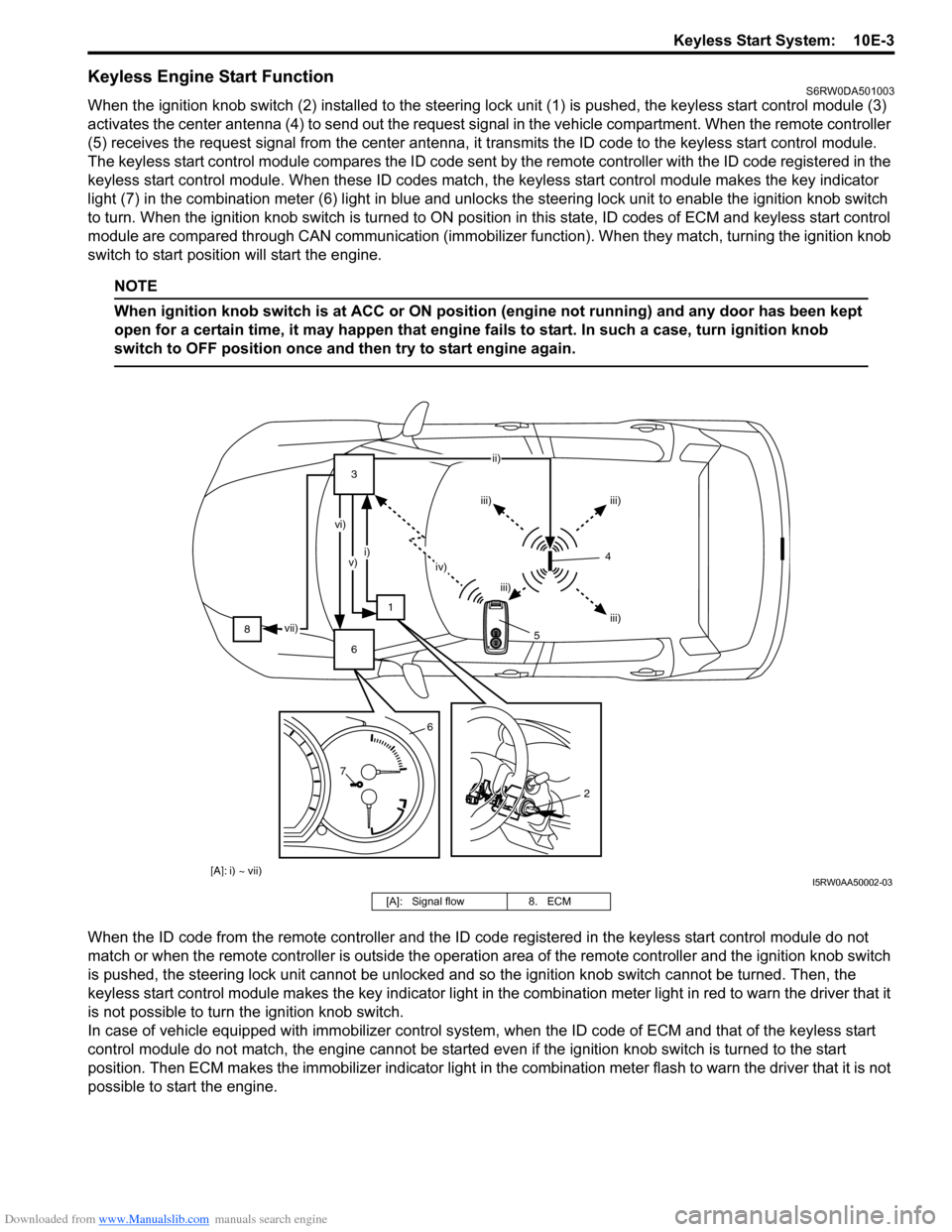
Keyless Engine Start FunctionS6RW0DA501003
When the ignition knob switch (2) installed to the steering lock unit (1) is pushed, the keyless start control module (3)
activates the center antenna (4) to send out the request signal in the vehicle compartment. When the remote controller
(5) receives the request signal from the center antenna, it transmits the ID code to the keyless start control module.
The keyless start control module compares the ID code sent by the remote controller with the ID code registered in the
keyless start control module. When these ID codes match, the keyless start control module makes the key indicator
light (7) in the combination meter (6) light in blue and unlocks the steering lock unit to enable the ignition knob switch
to turn. When the ignition knob switch is turned to ON position in this state, ID codes of ECM and keyless start control
module are compared through CAN communication (immobilizer function). When they match, turning the ignition knob
switch to start position will start the engine.
NOTE
When ignition knob switch is at ACC or ON position (engine not running) and any door has been kept
open for a certain time, it may happen that engine fails to start. In such a case, turn ignition knob
switch to OFF position once and then try to start engine again.
When the ID code from the remote controller and the ID code registered in the keyless start control module do not
match or when the remote controller is outside the operation area of the remote controller and the ignition knob switch
is pushed, the steering lock unit cannot be unlocked and so the ignition knob switch cannot be turned. Then, the
keyless start control module makes the key indicator light in the combination meter light in red to warn the driver that it
is not possible to turn the ignition knob switch.
In case of vehicle equipped with immobilizer control system, when the ID code of ECM and that of the keyless start
control module do not match, the engine cannot be started even if the ignition knob switch is turned to the start
position. Then ECM makes the immobilizer indicator light in the combination meter flash to warn the driver that it is not
possible to start the engine.
[A]: i) ~ vii)
83
1
6ii)
iii) iii)
iii) iii) iv) i)
v) vi)
vii)
76
2
4
5
I5RW0AA50002-03
[A]: Signal flow 8. ECM
Page 1526 of 1556
Downloaded from www.Manualslib.com manuals search engine 10E-4 Keyless Start System:
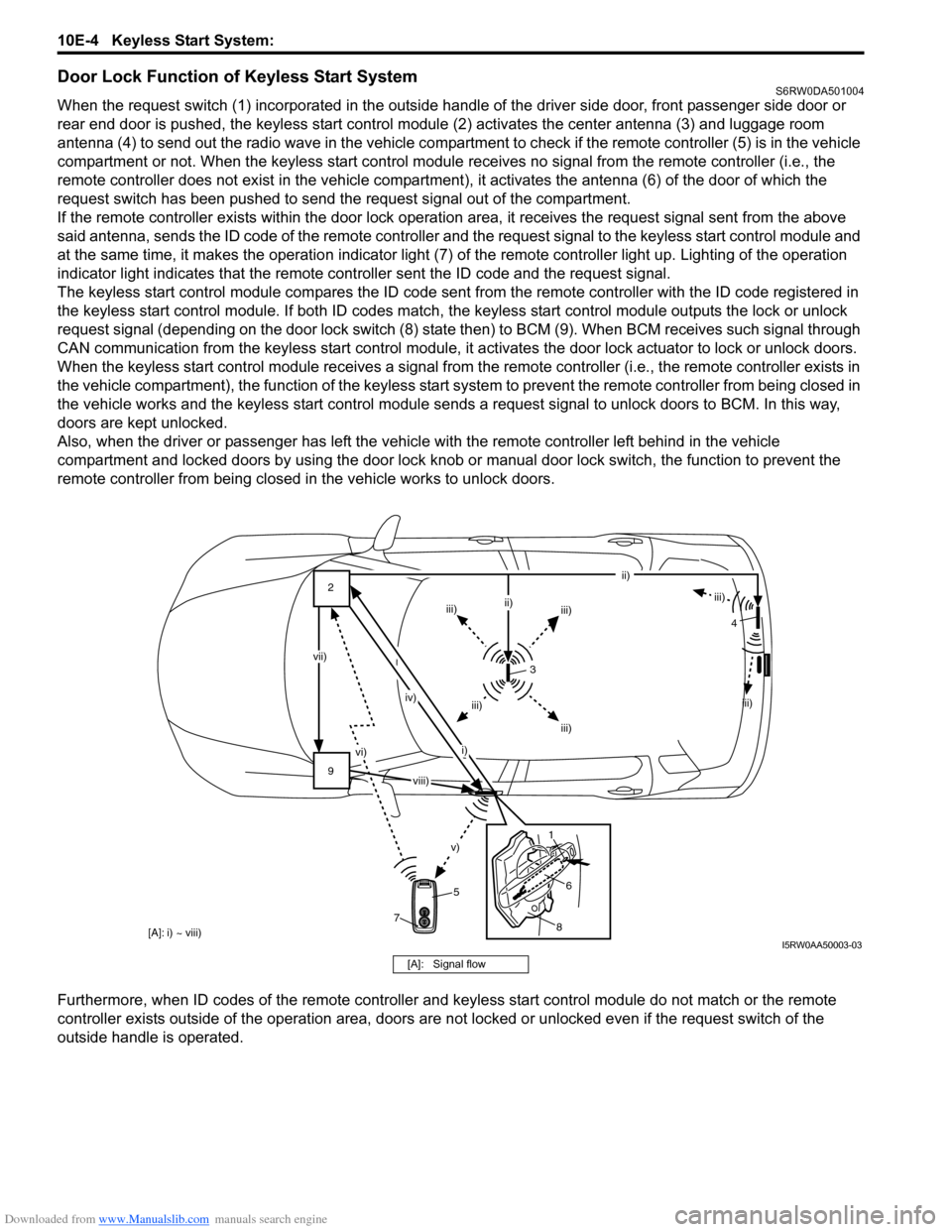
Door Lock Function of Keyless Start SystemS6RW0DA501004
When the request switch (1) incorporated in the outside handle of the driver side door, front passenger side door or
rear end door is pushed, the keyless start control module (2) activates the center antenna (3) and luggage room
antenna (4) to send out the radio wave in the vehicle compartment to check if the remote controller (5) is in the vehicle
compartment or not. When the keyless start control module receives no signal from the remote controller (i.e., the
remote controller does not exist in the vehicle compartment), it activates the antenna (6) of the door of which the
request switch has been pushed to send the request signal out of the compartment.
If the remote controller exists within the door lock operation area, it receives the request signal sent from the above
said antenna, sends the ID code of the remote controller and the request signal to the keyless start control module and
at the same time, it makes the operation indicator light (7) of the remote controller light up. Lighting of the operation
indicator light indicates that the remote controller sent the ID code and the request signal.
The keyless start control module compares the ID code sent from the remote controller with the ID code registered in
the keyless start control module. If both ID codes match, the keyless start control module outputs the lock or unlock
request signal (depending on the door lock switch (8) state then) to BCM (9). When BCM receives such signal through
CAN communication from the keyless start control module, it activates the door lock actuator to lock or unlock doors.
When the keyless start control module receives a signal from the remote controller (i.e., the remote controller exists in
the vehicle compartment), the function of the keyless start system to prevent the remote controller from being closed in
the vehicle works and the keyless start control module sends a request signal to unlock doors to BCM. In this way,
doors are kept unlocked.
Also, when the driver or passenger has left the vehicle with the remote controller left behind in the vehicle
compartment and locked doors by using the door lock knob or manual door lock switch, the function to prevent the
remote controller from being closed in the vehicle works to unlock doors.
Furthermore, when ID codes of the remote controller and keyless start control module do not match or the remote
controller exists outside of the operation area, doors are not locked or unlocked even if the request switch of the
outside handle is operated.
[A]: i) ~ viii)
9 2
vi)
v)
vii)
iv)
i)ii)
iii)
iii)iii) ii)
iii)
iii) iii)
3
5
8
6 14
7
viii)
I5RW0AA50003-03
[A]: Signal flow
Page 1527 of 1556
Downloaded from www.Manualslib.com manuals search engine Keyless Start System: 10E-5
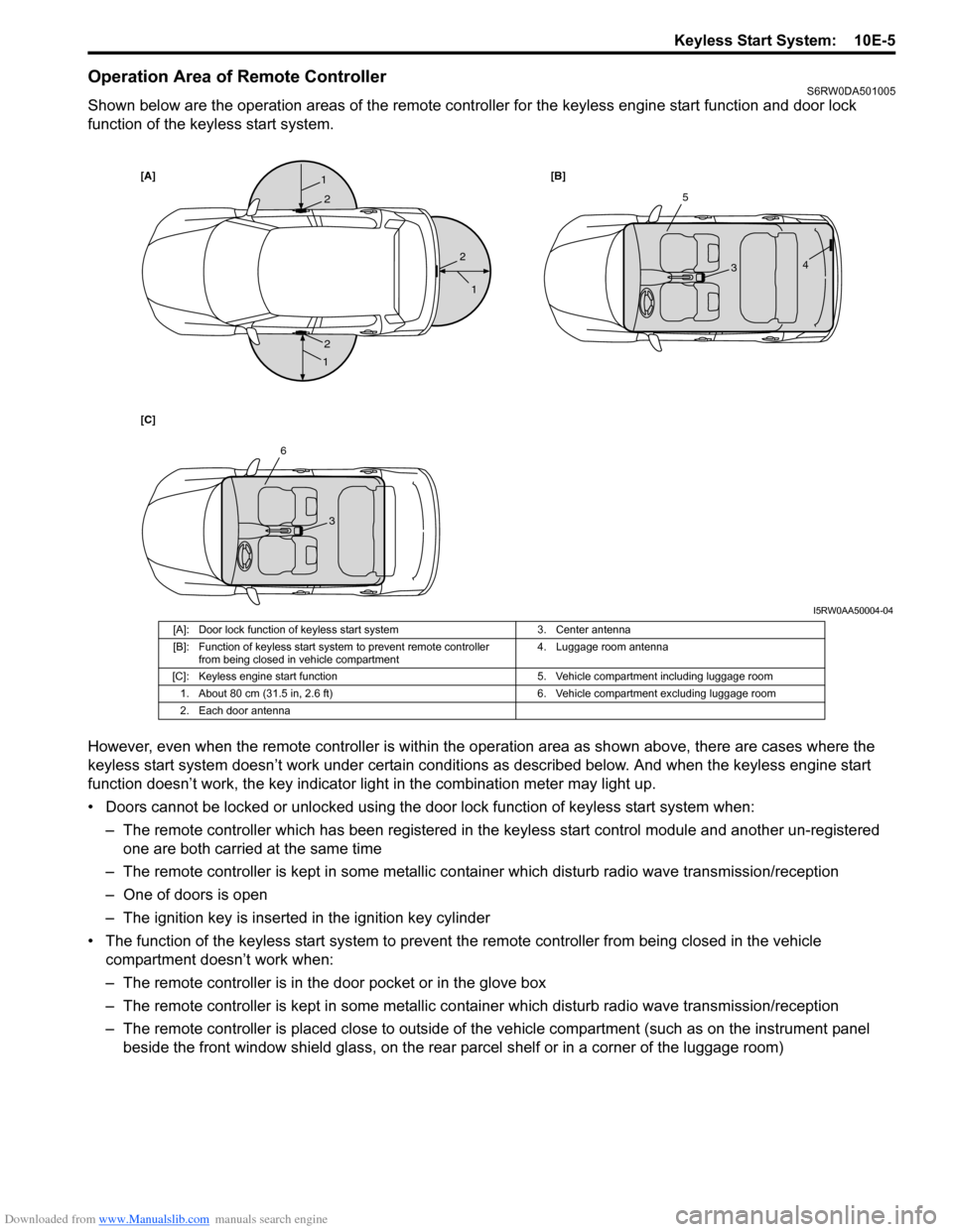
Operation Area of Remote ControllerS6RW0DA501005
Shown below are the operation areas of the remote controller for the keyless engine start function and door lock
function of the keyless start system.
However, even when the remote controller is within the operation area as shown above, there are cases where the
keyless start system doesn’t work under certain conditions as described below. And when the keyless engine start
function doesn’t work, the key indicator light in the combination meter may light up.
• Doors cannot be locked or unlocked using the door lock function of keyless start system when:
– The remote controller which has been registered in the keyless start control module and another un-registered
one are both carried at the same time
– The remote controller is kept in some metallic container which disturb radio wave transmission/reception
– One of doors is open
– The ignition key is inserted in the ignition key cylinder
• The function of the keyless start system to prevent the remote controller from being closed in the vehicle
compartment doesn’t work when:
– The remote controller is in the door pocket or in the glove box
– The remote controller is kept in some metallic container which disturb radio wave transmission/reception
– The remote controller is placed close to outside of the vehicle compartment (such as on the instrument panel
beside the front window shield glass, on the rear parcel shelf or in a corner of the luggage room)
[A][B]
[C]1
1
1
2
2
25
34
6
3
I5RW0AA50004-04
[A]: Door lock function of keyless start system 3. Center antenna
[B]: Function of keyless start system to prevent remote controller
from being closed in vehicle compartment4. Luggage room antenna
[C]: Keyless engine start function 5. Vehicle compartment including luggage room
1. About 80 cm (31.5 in, 2.6 ft) 6. Vehicle compartment excluding luggage room
2. Each door antenna