2006 SUZUKI SX4 meter
[x] Cancel search: meterPage 274 of 1556

Downloaded from www.Manualslib.com manuals search engine 1C-6 Engine Electrical Devices:
Removal
1) Disconnect negative cable at battery.
2) Disconnect connector from APP sensor assembly.
3) Remove APP sensor assembly from its bracket.
Installation
Reverse removal procedure for installation noting the
following.
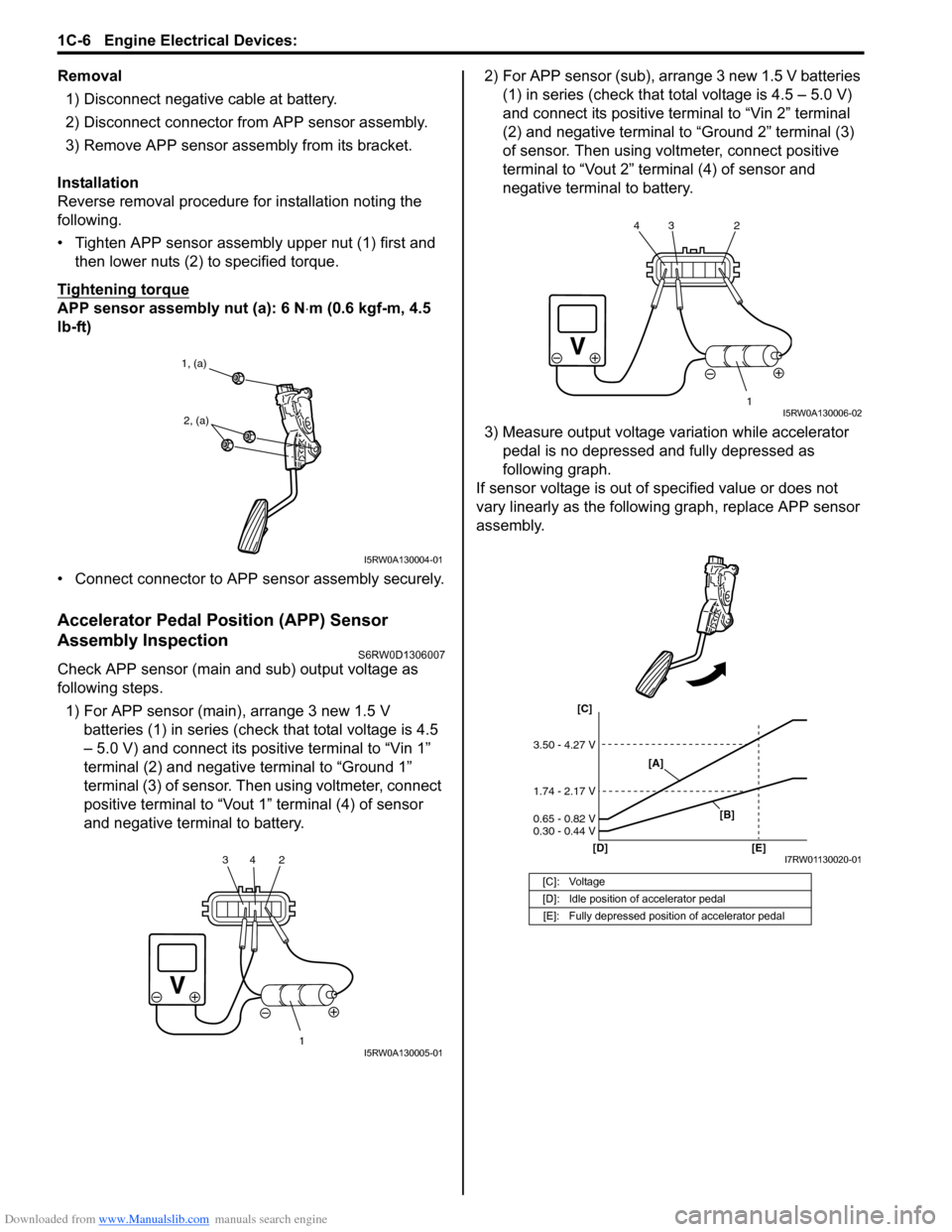
• Tighten APP sensor assembly upper nut (1) first and
then lower nuts (2) to specified torque.
Tightening torque
APP sensor assembly nut (a): 6 N⋅m (0.6 kgf-m, 4.5
lb-ft)
• Connect connector to APP sensor assembly securely.
Accelerator Pedal Position (APP) Sensor
Assembly Inspection
S6RW0D1306007
Check APP sensor (main and sub) output voltage as
following steps.
1) For APP sensor (main), arrange 3 new 1.5 V
batteries (1) in series (check that total voltage is 4.5
– 5.0 V) and connect its positive terminal to “Vin 1”
terminal (2) and negative terminal to “Ground 1”
terminal (3) of sensor. Then using voltmeter, connect
positive terminal to “Vout 1” terminal (4) of sensor
and negative terminal to battery.2) For APP sensor (sub), arrange 3 new 1.5 V batteries
(1) in series (check that total voltage is 4.5 – 5.0 V)
and connect its positive terminal to “Vin 2” terminal
(2) and negative terminal to “Ground 2” terminal (3)
of sensor. Then using voltmeter, connect positive
terminal to “Vout 2” terminal (4) of sensor and
negative terminal to battery.
3) Measure output voltage variation while accelerator
pedal is no depressed and fully depressed as
following graph.
If sensor voltage is out of specified value or does not
vary linearly as the following graph, replace APP sensor
assembly.
1, (a)
2, (a)
I5RW0A130004-01
1 2 34I5RW0A130005-01
[C]: Voltage
[D]: Idle position of accelerator pedal
[E]: Fully depressed position of accelerator pedal
1 2 3 4I5RW0A130006-02
[C]
[D] [E]
3.50 - 4.27 V
1.74 - 2.17 V
0.65 - 0.82 V
0.30 - 0.44 V
[A]
[B]
I7RW01130020-01
Page 276 of 1556

Downloaded from www.Manualslib.com manuals search engine 1C-8 Engine Electrical Devices:
Heated Oxygen Sensor (HO2S-1 and HO2S-2)
Heater On-Vehicle Inspection (If Equipped)
S6RW0D1306010
1) Disconnect sensor connector.
2) Using ohmmeter, measure resistance between
terminals “V
B” and “GND” of sensor connector.
If found faulty, replace oxygen sensor.
NOTE
Temperature of sensor affects resistance
value largely. Make sure that sensor heater is
at correct temperature.
Resistance of oxygen sensor heater
HO2S-1: 5.0 – 6.4 Ω at 20 °C (68 °F)
HO2S-2: 11.7 – 14.5 Ω at 20 °C (68 °F)
Viewed from terminal side
3) Connect sensor connector securely.
Heated Oxygen Sensor (HO2S-1 and HO2S-2)
Removal and Installation (If Equipped)
S6RW0D1306011
Removal
WARNING!
To avoid danger of being burned, do not
touch exhaust system when system is hot.
Oxygen sensor removal should be performed
when system is cool.
1) Disconnect negative cable at battery.
2) Disconnect connector of heated oxygen sensor and
release its wire harness from clamps.
3) Perform following items before removing heated
oxygen sensor.
a) For HO2S-1, remove exhaust manifold referring
to “Exhaust Manifold Removal and Installation in
Section 1K”, if necessary.
b) For HO2S-2, hoist vehicle.
4) Remove heated oxygen sensor from exhaust pipe or
exhaust manifold.Installation
Reverse removal procedure noting the following.
• Tighten heated oxygen sensor (1) to specified torque.
Tightening torque
Heated oxygen sensor (a): 45 N·m (4.5 kgf-m,
32.5 lb-ft)
• Install exhaust manifold referring to “Exhaust Manifold
Removal and Installation in Section 1K”, if removed.
• Connect connector of heated oxygen sensor (1) and
clamp wire harness securely.
• After installing heated oxygen sensor, start engine
and check that no exhaust gas leakage exists.
[A]: HO2S-1 [B]: HO2S-2
I4RS0A130006-01
[A]: HO2S-1 [B]: HO2S-2
[A]
[B]
1, (a)
1, (a)
I3RM0A130007-01
Page 278 of 1556

Downloaded from www.Manualslib.com manuals search engine 1C-10 Engine Electrical Devices:
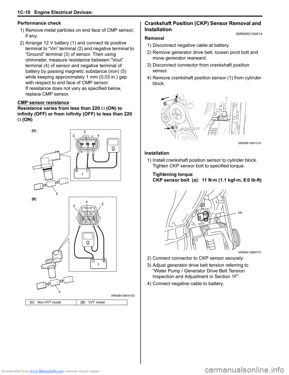
Performance check
1) Remove metal particles on end face of CMP sensor,
if any.
2) Arrange 12 V battery (1) and connect its positive
terminal to “Vin” terminal (2) and negative terminal to
“Ground” terminal (3) of sensor. Then using
ohmmeter, measure resistance between “Vout”
terminal (4) of sensor and negative terminal of
battery by passing magnetic substance (iron) (5)
while keeping approximately 1 mm (0.03 in.) gap
with respect to end face of CMP sensor.
If resistance does not vary as specified below,
replace CMP sensor.
CMP sensor resistance
Resistance varies from less than 220 Ω (ON) to
infinity (OFF) or from infinity (OFF) to less than 220
Ω (ON)
Crankshaft Position (CKP) Sensor Removal and
Installation
S6RW0D1306014
Removal
1) Disconnect negative cable at battery.
2) Remove generator drive belt, loosen pivot bolt and
move generator rearward.
3) Disconnect connector from crankshaft position
sensor.
4) Remove crankshaft position sensor (1) from cylinder
block.
Installation
1) Install crankshaft position sensor to cylinder block.
Tighten CKP sensor bolt to specified torque.
Tightening torque
CKP sensor bolt (a): 11 N·m (1.1 kgf-m, 8.0 lb-ft)
2) Connect connector to CKP sensor securely.
3) Adjust generator drive belt tension referring to
“Water Pump / Generator Drive Belt Tension
Inspection and Adjustment in Section 1F”.
4) Connect negative cable to battery.
[A]: Non-VVT model [B]: VVT model
I4RS0B130016-02
I2RH0B130012-01
(a)
I4RS0A130007-01
Page 279 of 1556

Downloaded from www.Manualslib.com manuals search engine Engine Electrical Devices: 1C-11
Crankshaft Position (CKP) Sensor InspectionS6RW0D1306015
Visual check
• Check that O-ring is free from damage.
• Check that end face of sensor and signal pulley tooth
are free from any metal particles and damage.
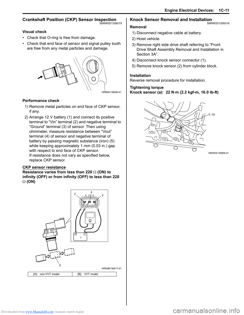
Performance check
1) Remove metal particles on end face of CKP sensor,
if any.
2) Arrange 12 V battery (1) and connect its positive
terminal to “Vin” terminal (2) and negative terminal to
“Ground” terminal (3) of sensor. Then using
ohmmeter, measure resistance between “Vout”
terminal (4) of sensor and negative terminal of
battery by passing magnetic substance (iron) (5)
while keeping approximately 1 mm (0.03 in.) gap
with respect to end face of CKP sensor.
If resistance does not vary as specified below,
replace CKP sensor.
CKP sensor resistance
Resistance varies from less than 220 Ω (ON) to
infinity (OFF) or from infinity (OFF) to less than 220
Ω (ON)
Knock Sensor Removal and InstallationS6RW0D1306016
Removal
1) Disconnect negative cable at battery.
2) Hoist vehicle.
3) Remove right side drive shaft referring to “Front
Drive Shaft Assembly Removal and Installation in
Section 3A”.
4) Disconnect knock sensor connector (1).
5) Remove knock sensor (2) from cylinder block.
Installation
Reverse removal procedure for installation.
Tightening torque
Knock sensor (a): 22 N·m (2.2 kgf-m, 16.0 lb-ft)
[A]: non-VVT model [B]: VVT model
I3RB0A130006-01
I4RS0B130017-01
1
2, (a)
I5RW0A130009-01
Page 280 of 1556

Downloaded from www.Manualslib.com manuals search engine 1C-12 Engine Electrical Devices:
Main Relay, Fuel Pump Relay, Starting Motor
Control Relay, Throttle Actuator Control Relay
and Radiator Cooling Fan Relay Inspection
S6RW0D1306017
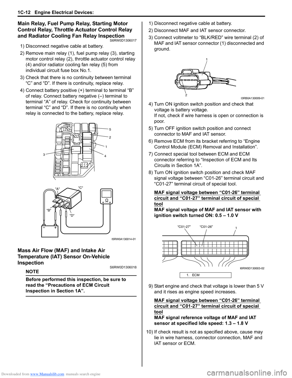
1) Disconnect negative cable at battery.
2) Remove main relay (1), fuel pump relay (3), starting
motor control relay (2), throttle actuator control relay
(4) and/or radiator cooling fan relay (5) from
individual circuit fuse box No.1.
3) Check that there is no continuity between terminal
“C” and “D”. If there is continuity, replace relay.
4) Connect battery positive (+) terminal to terminal “B”
of relay. Connect battery negative (–) terminal to
terminal “A” of relay. Check for continuity between
terminal “C” and “D”. If there is no continuity when
relay is connected to the battery, replace relay.
Mass Air Flow (MAF) and Intake Air
Temperature (IAT) Sensor On-Vehicle
Inspection
S6RW0D1306018
NOTE
Before performed this inspection, be sure to
read the “Precautions of ECM Circuit
Inspection in Section 1A”.
1) Disconnect negative cable at battery.
2) Disconnect MAF and IAT sensor connector.
3) Connect voltmeter to “BLK/RED” wire terminal (2) of
MAF and IAT sensor connector (1) disconnected and
ground.
4) Turn ON ignition switch position and check that
voltage is battery voltage.
If not, check if wire harness is open or connection is
poor.
5) Turn OFF ignition switch position and connect
connector to MAF and IAT sensor.
6) Remove ECM from its bracket referring to “Engine
Control Module (ECM) Removal and Installation”.
7) Connect special tool between ECM and ECM
connector referring to “Inspection of ECM and Its
Circuits in Section 1A”.
8) Turn ON ignition switch position and check MAF
signal voltage between “C01-26” terminal circuit and
“C01-27” terminal circuit of special tool.
MAF signal voltage between “C01-26” terminal
circuit and “C01-27” terminal circuit of special
tool
MAF signal voltage of MAF and IAT sensor with
ignition switch turned ON: 0.5 – 1.0 V
9) Start engine and check that voltage is lower than 5 V
and it rises as engine speed increases.
MAF signal voltage between “C01-26” terminal
circuit and “C01-27” terminal circuit of special
tool
MAF signal reference voltage of MAF and IAT
sensor at specified Idle speed: 1.3 – 1.8 V
10) If check result is not as specified above, cause may
lie in wire harness, connector connection, MAF and
IAT sensor or ECM.
"D" "B""A""C"
2
1
4 3
5
I5RW0A130014-01
1. ECM
I3RB0A130009-01
“C01-27” “C01-26”
1
I6RW0D130003-02
Page 290 of 1556

Downloaded from www.Manualslib.com manuals search engine 1D-8 Engine Mechanical:
2) Lift down the valve by turning crankshaft to 360°.
3) Hold tappet at that position using special tool as
follows.
a) Remove its housing bolts.
b) Check housing No. and select special tool
corresponding to housing No., referring to
“Special tool selection table”.
Special tool selection table
c) Hold down the tappet so as not to contact the
shim by installing special tool on camshaft
housing with housing bolt (1) tighten housing
bolts by hand.
Special tool
(A): 09916–67020
(A): 09916–670214) Turn camshaft by approximately 90° clockwise and
remove shim (3).
WARNING!
Never put in the hand between camshaft and
tappet.
5) Using a micrometer (2), measure the thickness of
the removed shim (1), and determine replacement
shim by calculating the thickness of new shim with
the following formula and table.
Shim thickness specification
Intake side:
A = B + C – 0.20 mm (0.008 in.)
Exhaust side:
A = B + C – 0.30 mm (0.012 in.)
A: Thickness of new shim
B: Thickness of removed shim
C: Measured valve clearance
For example of intake side:
When thickness of removed shim is 2.40 mm (0.094
in.), and measured valve clearance is 0.45 mm
(0.018 in.).
A = 2.40 mm (0.094 in.) + 0.45 mm (0.018 in.) – 0.20
mm (0.008 in.) = 2.65 mm (0.104 in.)
Calculated thickness of new shim = 2.65 mm (0.104
in.) No. on camshaft
housingEmbossed mark on special
tool
I2 IN2
I3, I4, I5 IN345
E2 EX2
E3, E4, E5 EX345A: I: Intake side or E: Exhaust side
B: Position from timing chain side
C: Pointing to timing chain side
I2RH0B140011-01
I5RW0C140003-01
1. Special tool 2. Magnet
I2RH0B140013-01
I2RH0B140014-01
Page 318 of 1556

Downloaded from www.Manualslib.com manuals search engine 1D-36 Engine Mechanical:
Camshaft, Tappet and Shim InspectionS6RW0D1406024
Intake Cam Timing Sprocket Assembly (For engine
with VVT)
Fit intake cam timing sprocket assembly to camshaft (2)
and hold hexagonal section of camshaft by using
spanner or the like.
Check if sprocket (1) is not turned by hand.
If moved, replace intake cam timing sprocket assembly.
Cam Wear
Using a micrometer, measure cam height “a”. If
measured height underruns its limit, replace camshaft.
Cam height “a”
[For engine with VVT]
[For engine without VVT]Camshaft Runout
Set camshaft between two “V” blocks, and measure its
runout by using a dial gauge.
If measured runout exceeds limit, replace camshaft.
Camshaft runout limit
0.10 mm (0.0039 in.)
Camshaft Journal Wear
Check camshaft journals and camshaft housings for
pitting, scratches, wear or damage.
If any malcondition is found, replace camshaft or cylinder
head with housing. Never replace cylinder head without
replacing housings.
Check clearance by using gauging plastic. Checking
procedure is as follows.
1) Clean housings and camshaft journals.
2) Remove all tappets with shims.
3) Install camshafts to cylinder head.
4) Place a piece of gauging plastic to full width of
journal of camshaft (parallel to camshaft).
5) Install camshaft housing. Cam height Standard Limit
Intake cam44.929 – 45.089 mm
(1.769 – 1.775 in.)44.80 mm
(1.764 in.)
Exhaust cam44.399 – 44.559 mm
(1.748 – 1.754 in.)44.28 mm
(1.743 in.)
Cam height Standard Limit
Intake cam44.919 – 45.079 mm
(1.768 – 1.775 in.)44.80 mm
(1.764 in.)
Exhaust cam44.399 – 44.559 mm
(1.748 – 1.754 in.)44.28 mm
(1.743 in.)
2 1
I3RH0B140043-01
I2RH0B140080-01
I2RH0B140081-01
I2RH0B140082-01
Page 319 of 1556

Downloaded from www.Manualslib.com manuals search engine Engine Mechanical: 1D-37
6) Tighten camshaft housing bolts evenly and gradually
in numerical order (“1” through “21”) by repeating
tightening sequence two or three times until
specified torque is obtained.
NOTE
Do not rotate camshaft while gauging plastic
is installed.
Tightening torque
Camshaft housing bolt (a): 11 N·m (1.1 kgf-m,
8.0 lb-ft)
7) Remove housing, and using scale (2) on gauging
plastic envelop, measure gauging plastic (1) width at
its widest point.
Camshaft journal clearance
[For engine with VVT system]
[For engine without VVT system]If measured camshaft journal clearance exceeds
limit, measure journal (housing) bore and outside
diameter of camshaft journal. Replace camshaft or
cylinder head assembly whichever the difference
from specification is greater.
Camshaft journal diameter [A]
[For engine with VVT system]
[For engine without VVT system]
Camshaft journal bearing bore [B]
[For engine with VVT system]
[For engine without VVT system] Standard Limit
Intake side
No.1 housing0.020 – 0.072 mm
(0.0008 – 0.0028 in.)0.10 mm
(0.0039 in.)
Others0.045 – 0.087 mm
(0.0018 – 0.0034 in.)0.12 mm
(0.0047 in.)
Standard Limit
0.045 – 0.087 mm
(0.0018 – 0.0034 in.)0.12 mm
(0.0047 in.)
“10”“9”
“2” “1”,(a) “6”“5” “14” “13”
“20”
“17”
“19”
“18”
“21”
“12”
“11”
“4” “3” “8”“7” “16” “15”
I3RH0B140041-01
I2RH0B140083-01
Item Standard
Intake side No.1 housing26.940 – 26.955 mm
(1.0606 – 1.0612 in.)
Exhaust side No.1
housing26.934 – 26.955 mm
(1.0604 – 1.0612 in.)
Others22.934 – 22.955 mm
(0.9029 – 0.9037 in.)
Item Standard
Intake and Exhaust side
No.1 housing26.934 – 26.955 mm
(1.0604 – 1.0612 in.)
Others22.934 – 22.955 mm
(0.9029 – 0.9037 in.)
Item Standard
Intake side No.1 housing30.000 – 30.015 mm
(1.1811 – 1.1816 in.)
Exhaust side No.1
housing27.000 – 27.021 mm
(1.0630 – 1.0638 in.)
Others23.000 – 23.021 mm
(0.9055 – 0.9063 in.)
Item Standard
Intake and Exhaust side
No.1 housing27.000 – 27.021 mm
(1.0630 – 1.0638 in.)
Others23.000 – 23.021 mm
(0.9055 – 0.9063 in.)