Page 1025 of 1556

Downloaded from www.Manualslib.com manuals search engine Air Conditioning System: Automatic Type 7B-85
Blower Motor Controller InspectionS6RW0D7226012
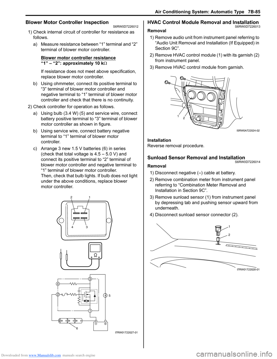
1) Check internal circuit of controller for resistance as
follows.
a) Measure resistance between “1” terminal and “2”
terminal of blower motor controller.
Blower motor controller resistance
“1” – “2”: approximately 10 kΩ
If resistance does not meet above specification,
replace blower motor controller.
b) Using ohmmeter, connect its positive terminal to
“3” terminal of blower motor controller and
negative terminal to “1” terminal of blower motor
controller and check that there is no continuity.
2) Check controller for operation as follows.
a) Using bulb (3.4 W) (5) and service wire, connect
battery positive terminal to “3” terminal of blower
motor controller as shown in figure.
b) Using service wire, connect battery negative
terminal to “1” terminal of blower motor
controller.
c) Arrange 3 new 1.5 V batteries (6) in series
(check that total voltage is 4.5 – 5.0 V) and
connect its positive terminal to “2” terminal of
blower motor controller and negative terminal to
“1” terminal of blower motor controller.
Then, check that bulb lights. If bulb does not light
under the above conditions, replace blower
motor controller.
HVAC Control Module Removal and InstallationS6RW0D7226013
Removal
1) Remove audio unit from instrument panel referring to
“Audio Unit Removal and Installation (If Equipped) in
Section 9C”.
2) Remove HVAC control module (1) with its garnish (2)
from instrument panel.
3) Remove HVAC control module from garnish.
Installation
Reverse removal procedure.
Sunload Sensor Removal and InstallationS6RW0D7226014
Removal
1) Disconnect negative (–) cable at battery.
2) Remove combination meter from instrument panel
referring to “Combination Meter Removal and
Installation in Section 9C”.
3) Remove sunload sensor (1) from instrument panel
by depressing tab and pushing sensor upward from
underneath.
4) Disconnect sunload sensor connector (2).
21
43
3
1 2 4
5
6I7RW01722027-01
12
I5RW0A722024-02
1
2
I7RW01722028-01
Page 1206 of 1556

Downloaded from www.Manualslib.com manuals search engine 9A-39 Wiring Systems:
30 A WIPCOMB switch
Windshield washer motor
Windshield wiper motor
Rear wiper relay
DRL controller
10 A IG1 SIGPower steering control module
A/T relay
Brake light switch
15 A A/B A/B SDM
10 A ABSABS control module
G sensor
10 A TAILCOMB switch
DRL controller
15 A STOP Brake light switch
20 A D/L BCM
15 A 4WD 4WD control module
10 A ST SIG Starting motor relay
15 A S/HSeat heater switch (Driver side)
Seat heater switch (Passenger side)
10 A IG2 SIG Blower fan relay
15 A RR FOG COMB switch
15 A DOMEAudio
BCM
COMB meter
DLC
ECM
Interior light
ICM
TCM
Rear interior light
Luggage compartment light
Main switch (Key switch)
Multi information display
KLS ECM
30 A RR DEFRear defogger relay
Mirror motor (R)
Mirror motor (L)
15 A HORN-HAZHorn relay
Flasher relay
BLANK BLANK BLANK
BLANK BLANK BLANK
30 A P/WPower window main switch
Front power window sub switch
Rear power window sub switch (R)
Rear power window sub switch (L) No. Fuse Description on the cover Protected circuit
Page 1208 of 1556
Downloaded from www.Manualslib.com manuals search engine 9A-41 Wiring Systems:
10 A ABSABS control module
G sensor
BLANK BLANK BLANK
15 A STOP Brake light switch
20 A D/L BCM
BLANK BLANK BLANK
10 A ST SIG Starting motor relay
BLANK BLANK BLANK
10 A IG2 SIG Blower fan relay
10 A TAIL Tail light relay
15 A DOMEAudio
BCM
COMB meter
DLC
ECM
Interior light
ICM
TCM
Rear interior light
Luggage compartment light
Main switch (Key switch)
Multi information display
KLS ECM
30 A RR DEFRear defogger relay
Mirror motor (R)
Mirror motor (L)
15 A HORN-HAZHorn relay
Flasher relay
BLANK BLANK BLANK
BLANK BLANK BLANK
30 A P/WPower window main switch
Front power window sub switch
Rear power window sub switch (R)
Rear power window sub switch (L) No. Fuse Description on the cover Protected circuit
Page 1295 of 1556
Downloaded from www.Manualslib.com manuals search engine Wiring Systems: 9A-128
RED
M
BLU/WHTYEL
BLK/WHTBLK/WHTBLU/WHTBLU/WHT
BLK/WHT
G1555
BRN
J/B
BLK/YEL
2
1G61
11
G65
Fan driver
4 2
1 3
Blower
fan
motor
G2736
1 327
6
FAN
Heater fan switch
42 5
1
3
30ABLW
6
10A
35IG2
SIG
Blower
fan
relay
E323
7
G2729
G309
J/C
1114
B
B
BLK
BLKBLK
BLK
BLU
1
Individual circuit
fuse box (No.1)
ECM
"A-5"BW
I6RW0C910997-02
Page 1297 of 1556
Downloaded from www.Manualslib.com manuals search engine Wiring Systems: 9A-130
G321
3
24
9
29G20
1025
G64
M
162152812127
31
M
2G65
BLK/WHT
GRY/BLUGRY/REDWHTBRN/WHTWHT/BLKORNPNK
WHTYELWHTWHT/BLUBRN/YEL
ORN
ORNORN
BLK/YEL
BLK
BLK/YEL
BLK/YEL
BLU
BLK/WHTGRY
30
4
BLU/REDBLK/WHTBLK
Fan
driver
Diode
#1
Auto
unit Blower
fan
motor
EVAP thermistor
Mode
selecting
actuatorTemperature
control
actuator
10AIG2
SIG
35
10ABACK
21
30ABLW
6
265 14
G63
M
265 142
G255
1G62
G61 G273
1
2
6G27289E3237
1
5V5V
5V5V12V
12V
11
G309
J/C
Individual
circuit
fuse box
(No.1)
B
B
G310
J/C
B
BB
B
G310
J/C
A
AA
BLK
14
BLK
11
Fresh/
Recircle
actuator
G342
1
PNK/BLK
ORN
Room temperature
sensor
5V
J/B
42 5
1
3
Blower fan
relay
22181917
RED/BLK
RED/BLK
RED/BLK
REDGRN/REDGRN
12V
J/C
B
BG306
B
456
2
1G35
Sunlight sensor
ORN
5V
M
I6RW0C910999-02
Page 1479 of 1556
Downloaded from www.Manualslib.com manuals search engine Body Electrical Control System: 10B-6
Connector Layout Diagram of BCM and Junction BlockS6RW0DA202002
BCM and Junction Block Connectors (Viewed from Harness Side)
I6RW0CA20004-01
[A]: Junction block (viewed from BCM side) 2. Junction block 5. Rear wiper relay
[B]: Junction block (viewed from relay side) 3. Blower motor relay 6. Rear end door window defogger relay
1. BCM 4. Horn relay 7. Turn signal and hazard warning relay