2006 SUZUKI SX4 Oil change
[x] Cancel search: Oil changePage 818 of 1556
Downloaded from www.Manualslib.com manuals search engine 5B-6 Manual Transmission/Transaxle:
Manual Transaxle Oil ChangeS6RW0D5206002
1) Before changing or inspecting oil, be sure to stop
engine and lift vehicle horizontally.
2) With vehicle lifted up, check leakage.
If leakage exists, correct it.
NOTE
Whenever vehicle is hoisted for any other
service work than oil change, also be sure to
check for oil leakage.
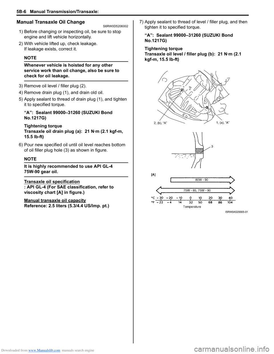
3) Remove oil level / filler plug (2).
4) Remove drain plug (1), and drain old oil.
5) Apply sealant to thread of drain plug (1), and tighten
it to specified torque.
“A”: Sealant 99000–31260 (SUZUKI Bond
No.1217G)
Tightening torque
Transaxle oil drain plug (a): 21 N·m (2.1 kgf-m,
15.5 lb-ft)
6) Pour new specified oil until oil level reaches bottom
of oil filler plug hole (3) as shown in figure.
NOTE
It is highly recommended to use API GL-4
75W-90 gear oil.
Transaxle oil specification
: API GL-4 (For SAE classification, refer to
viscosity chart [A] in figure.)
Manual transaxle oil capacity
Reference: 2.5 liters (5.3/4.4 US/lmp. pt.)7) Apply sealant to thread of level / filler plug, and then
tighten it to specified torque.
“A”: Sealant 99000–31260 (SUZUKI Bond
No.1217G)
Tightening torque
Transaxle oil level / filler plug (b): 21 N·m (2.1
kgf-m, 15.5 lb-ft)
I5RW0A520005-01
Page 819 of 1556

Downloaded from www.Manualslib.com manuals search engine Manual Transmission/Transaxle: 5B-7
Differential Side Oil Seal ReplacementS6RW0D5206003
1) Lift up vehicle and drain transaxle oil.
2) Remove drive shaft assembly and center shaft
referring to “Front Drive Shaft Assembly Removal
and Installation in Section 3A”.
3) Remove oil seal (1) by using special tool.
Special tool
(A): 09913–50121
4) Install a new oil seal (1) by using special tool.
NOTE
• When installing oil seal, face its spring
side inward.
• Install oil seal horizontally to surface of
case.
Special tool
(A): 09913–75810
(B): 09913–75510
Distance between case and right oil seal for 2WD
“a”: 9.5 – 10.5 mm (0.37 – 0.41 in.)
Distance between case and left oil seal
“b”: 0 – 1.0 mm (0 – 0.04 in.)5) Apply grease to oil seal lip and at the same time
check drive shaft where oil seal contacts and make
sure of its smoothness.
“A”: Grease 99000–25011 (SUZUKI Super
Grease A)
6) Insert drive shaft assembly and center shaft referring
to “Front Drive Shaft Assembly Removal and
Installation in Section 3A”.
7) Pour transaxle oil referring to “Manual Transaxle Oil
Change”.
(A)
1I5RW0A520006-02
“b”
“a”
1, “A”
(A)(B)
I5RW0A520051-01
Page 824 of 1556

Downloaded from www.Manualslib.com manuals search engine 5B-12 Manual Transmission/Transaxle:
Manual Transaxle Unit Dismounting and
Remounting
S6RW0D5206010
Dismounting
1) Drain coolant.
2) Remove battery and tray with ECM.
3) Remove air cleaner case and resonator.
4) Remove clutch fluid pipe referring to “Clutch Fluid
Pipe Removal and Installation in Section 5C”.
5) Disconnect back up light switch coupler and undo
wiring harness clamps.
6) Disconnect gear shift and gear select control cables
(1) from transaxle.
7) Remove earth cable from transaxle.
8) Remove water inlet pipe.
9) Remove starting motor referring to “Starting Motor
Dismounting and Remounting in Section 1I”.
10) Remove transaxle to engine bolts (1) of upper side.
11) Drain transaxle oil and transfer oil, if equipped.
12) Remove engine under covers.
13) Remove drive shaft assembly and center shaft
referring to “Front Drive Shaft Assembly Removal
and Installation in Section 3A”.
14) Remove exhaust No.1, No.2 and No.3 pipes
referring to “Exhaust Pipe and Muffler Removal and
Installation in Section 1K”.
15) Remove suspension frame, engine front mounting
member and engine mounting member referring to
“Front Suspension Frame, Stabilizer Bar and/or
Bushing Removal and Installation in Section 2B” and
“Engine Mountings Components in Section 1D”.16) Remove transfer referring to “Transfer Dismounting
and Remounting in Section 3C”, if equipped.
17) Remove clutch housing lower plate.
18) Support transaxle with transmission jack.
19) Remove left mounting (1) and left mounting bracket
(2).
20) Remove stiffener bolts (2), transaxle to engine bolts
(1) and nut of lower side, and then lower transaxle.
Remounting
CAUTION!
• Care should be taken not to scratch oil
seal lip with drive shaft while raising
transaxle.
• Do not hit drive shaft joint with hammer
when installing it into differential gear.
Reverse dismounting procedure for remounting of
transaxle, noting the following points.
• Tighten each bolts and nuts to specified torque
referring to “Manual Transaxle Unit Components” and
“Engine Mountings Components in Section 1D”.
• Set each clamp for wiring securely.
• Fill transaxle oil and transfer oil referring to “Manual
Transaxle Oil Change” and “Transfer Oil Change in
Section 3C”.
• Connect battery and check function of engine, clutch
and transaxle.
1
I5RW0A520011-01
1
I5RW0A520012-01
1
2
I5RW0A520013-01
1
2I5RW0A520014-01
Page 1129 of 1556
Downloaded from www.Manualslib.com manuals search engine Air Bag System: 8B-90
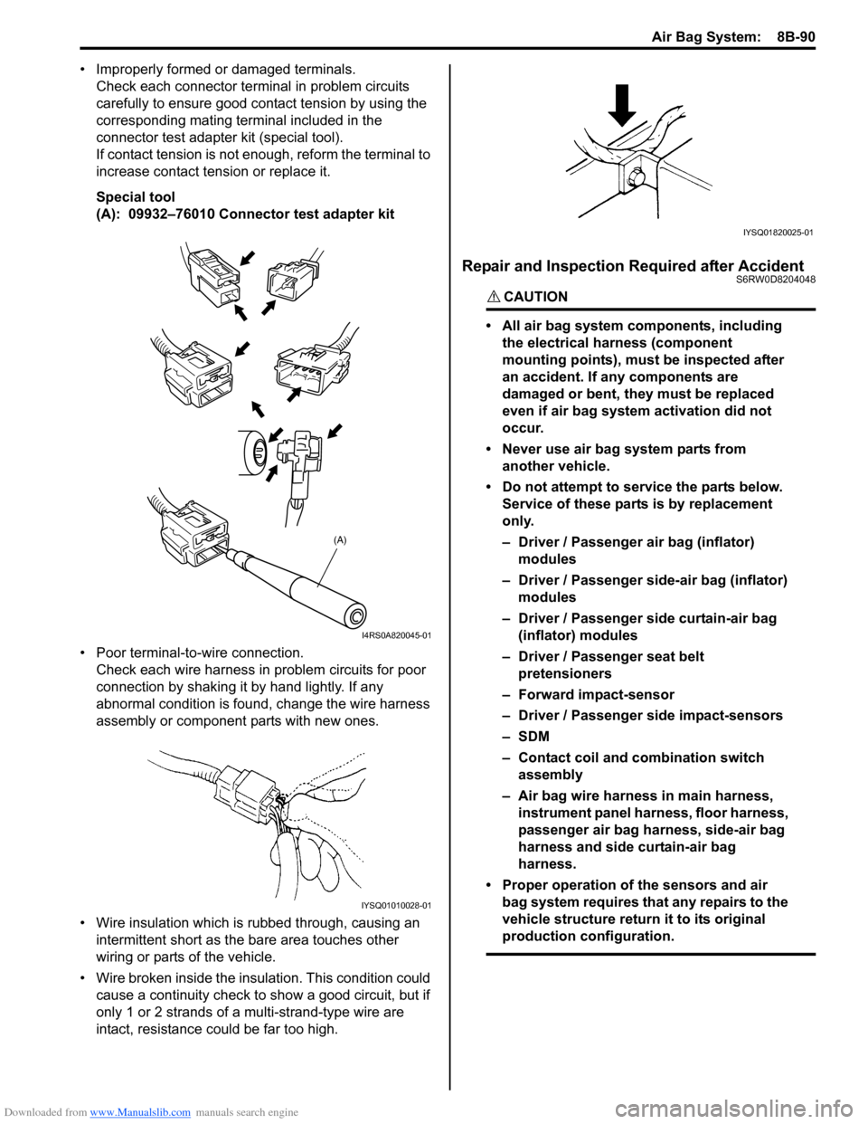
• Improperly formed or damaged terminals.
Check each connector terminal in problem circuits
carefully to ensure good contact tension by using the
corresponding mating terminal included in the
connector test adapter kit (special tool).
If contact tension is not enough, reform the terminal to
increase contact tension or replace it.
Special tool
(A): 09932–76010 Connector test adapter kit
• Poor terminal-to-wire connection.
Check each wire harness in problem circuits for poor
connection by shaking it by hand lightly. If any
abnormal condition is found, change the wire harness
assembly or component parts with new ones.
• Wire insulation which is rubbed through, causing an
intermittent short as the bare area touches other
wiring or parts of the vehicle.
• Wire broken inside the insulation. This condition could
cause a continuity check to show a good circuit, but if
only 1 or 2 strands of a multi-strand-type wire are
intact, resistance could be far too high.
Repair and Inspection Required after AccidentS6RW0D8204048
CAUTION!
• All air bag system components, including
the electrical harness (component
mounting points), must be inspected after
an accident. If any components are
damaged or bent, they must be replaced
even if air bag system activation did not
occur.
• Never use air bag system parts from
another vehicle.
• Do not attempt to service the parts below.
Service of these parts is by replacement
only.
– Driver / Passenger air bag (inflator)
modules
– Driver / Passenger side-air bag (inflator)
modules
– Driver / Passenger side curtain-air bag
(inflator) modules
– Driver / Passenger seat belt
pretensioners
– Forward impact-sensor
– Driver / Passenger side impact-sensors
–SDM
– Contact coil and combination switch
assembly
– Air bag wire harness in main harness,
instrument panel harness, floor harness,
passenger air bag harness, side-air bag
harness and side curtain-air bag
harness.
• Proper operation of the sensors and air
bag system requires that any repairs to the
vehicle structure return it to its original
production configuration.
(A)
I4RS0A820045-01
IYSQ01010028-01
IYSQ01820025-01
Page 1329 of 1556
Downloaded from www.Manualslib.com manuals search engine Lighting Systems: 9B-10
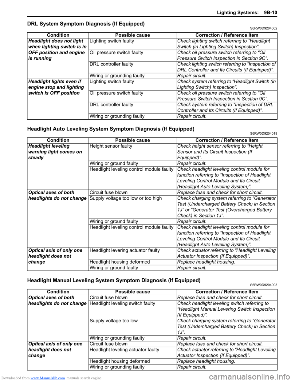
DRL System Symptom Diagnosis (If Equipped)S6RW0D9204002
Headlight Auto Leveling System Symptom Diagnosis (If Equipped)S6RW0D9204019
Headlight Manual Leveling System Symptom Diagnosis (If Equipped)S6RW0D9204003
Condition Possible cause Correction / Reference Item
Headlight does not light
when lighting switch is in
OFF position and engine
is runningLighting switch faultyCheck lighting switch referring to “Headlight
Switch (in Lighting Switch) Inspection”.
Oil pressure switch faultyCheck oil pressure switch referring to “Oil
Pressure Switch Inspection in Section 9C”.
DRL controller faultyCheck lighting switch referring to “Inspection of
DRL Controller and Its Circuits (If Equipped)”.
Wiring or grounding faultyRepair circuit.
Headlight lights even if
engine stop and lighting
switch is OFF positionLighting switch faultyCheck system referring to “Headlight Switch (in
Lighting Switch) Inspection”.
Oil pressure switch faultyCheck oil pressure switch referring to “Oil
Pressure Switch Inspection in Section 9C”.
DRL controller faultyCheck system referring to “Inspection of DRL
Controller and Its Circuits (If Equipped)”.
Wiring or grounding faultyRepair circuit.
Condition Possible cause Correction / Reference Item
Headlight leveling
warning light comes on
steadyHeight sensor faultyCheck height sensor referring to “Height
Sensor and Its Circuit Inspection (If
Equipped)”.
Wiring or ground faultyRepair circuit.
Headlight leveling control module faultyCheck headlight leveling control module for
function referring to “Inspection of Headlight
Leveling Control Module and Its Circuit
(Headlight Auto Leveling System)”.
Optical axes of both
headlights do not changeCircuit fuse blownReplace fuse and check for short circuit.
Supply voltage too low or too highCheck charging system referring to “Generator
Test (Undercharged Battery Check) in Section
1J” or “Generator Test (Overcharged Battery
Check) in Section 1J”.
Wiring or ground faultyRepair circuit.
Headlight leveling control module faultyCheck headlight leveling control module for
function referring to “Inspection of Headlight
Leveling Control Module and Its Circuit
(Headlight Auto Leveling System)”.
Optical axis of only one
headlight does not
changeHeadlight levering actuator faultyCheck actuator referring to “Headlight Leveling
Actuator Inspection (If Equipped)”.
Headlight housing deformedReplace headlight housing.
Wiring or ground faultyRepair circuit.
Condition Possible cause Correction / Reference Item
Optical axes of both
headlights do not changeCircuit fuse blownReplace fuse and check for short circuit.
Headlight leveling switch faultyCheck headlight leveling switch referring to
“Headlight Manual Levering Switch Inspection
(If Equipped)”.
Supply voltage too lowCheck charging system referring to “Generator
Test (Undercharged Battery Check) in Section
1J”.
Wiring or grounding faultyRepair circuit.
Optical axis of only one
headlight does not
changeCircuit fuse blownReplace fuse and check for short circuit.
Headlight leveling actuator faultyCheck actuator referring to “Headlight Leveling
Actuator Inspection (If Equipped)”.
Headlight housing deformedReplace headlight housing.
Wiring or grounding faultyRepair circuit.
Page 1365 of 1556
Downloaded from www.Manualslib.com manuals search engine Instrumentation / Driver Info. / Horn: 9C-13
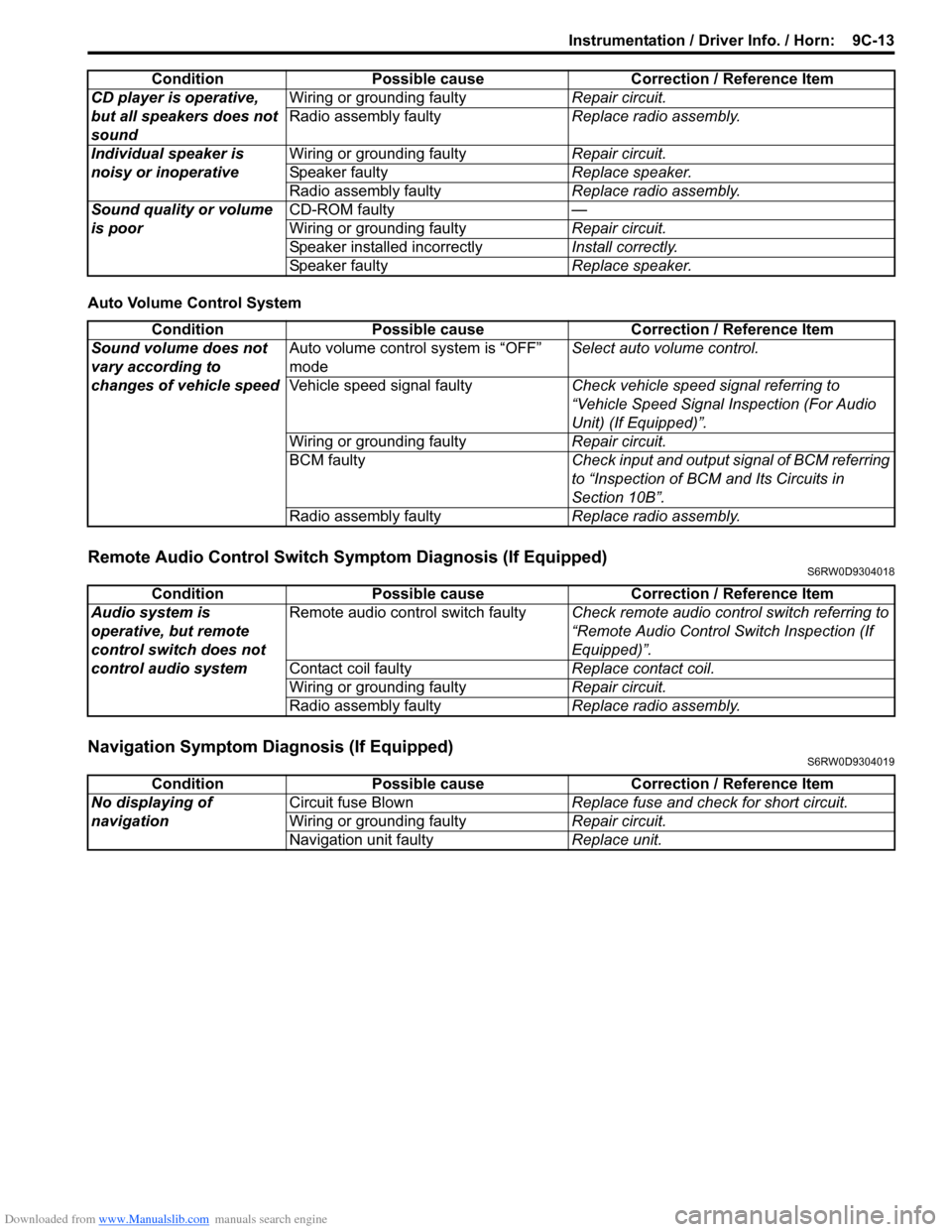
Auto Volume Control System
Remote Audio Control Switch Symptom Diagnosis (If Equipped)S6RW0D9304018
Navigation Symptom Diagnosis (If Equipped)S6RW0D9304019
CD player is operative,
but all speakers does not
soundWiring or grounding faultyRepair circuit.
Radio assembly faultyReplace radio assembly.
Individual speaker is
noisy or inoperativeWiring or grounding faultyRepair circuit.
Speaker faultyReplace speaker.
Radio assembly faultyReplace radio assembly.
Sound quality or volume
is poorCD-ROM faulty—
Wiring or grounding faultyRepair circuit.
Speaker installed incorrectlyInstall correctly.
Speaker faultyReplace speaker. Condition Possible cause Correction / Reference Item
Condition Possible cause Correction / Reference Item
Sound volume does not
vary according to
changes of vehicle speedAuto volume control system is “OFF”
modeSelect auto volume control.
Vehicle speed signal faultyCheck vehicle speed signal referring to
“Vehicle Speed Signal Inspection (For Audio
Unit) (If Equipped)”.
Wiring or grounding faultyRepair circuit.
BCM faultyCheck input and output signal of BCM referring
to “Inspection of BCM and Its Circuits in
Section 10B”.
Radio assembly faultyReplace radio assembly.
Condition Possible cause Correction / Reference Item
Audio system is
operative, but remote
control switch does not
control audio systemRemote audio control switch faultyCheck remote audio control switch referring to
“Remote Audio Control Switch Inspection (If
Equipped)”.
Contact coil faultyReplace contact coil.
Wiring or grounding faultyRepair circuit.
Radio assembly faultyReplace radio assembly.
Condition Possible cause Correction / Reference Item
No displaying of
navigationCircuit fuse BlownReplace fuse and check for short circuit.
Wiring or grounding faultyRepair circuit.
Navigation unit faultyReplace unit.
Page 1367 of 1556
Downloaded from www.Manualslib.com manuals search engine Instrumentation / Driver Info. / Horn: 9C-15
3) Remove center ventilation louver referring to Step 1)
and 2) of “Information Display (Clock) Removal and
Installation”.
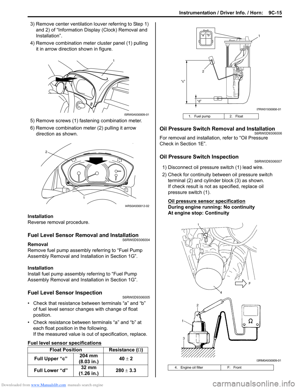
4) Remove combination meter cluster panel (1) pulling
it in arrow direction shown in figure.
5) Remove screws (1) fastening combination meter.
6) Remove combination meter (2) pulling it arrow
direction as shown.
Installation
Reverse removal procedure.
Fuel Level Sensor Removal and InstallationS6RW0D9306004
Removal
Remove fuel pump assembly referring to “Fuel Pump
Assembly Removal and Installation in Section 1G”.
Installation
Install fuel pump assembly referring to “Fuel Pump
Assembly Removal and Installation in Section 1G”.
Fuel Level Sensor InspectionS6RW0D9306005
• Check that resistance between terminals “a” and “b”
of fuel level sensor changes with change of float
position.
• Check resistance between terminals “a” and “b” at
each float position in the following.
If the measured value is out of specification, replace.
Fuel level sensor specifications
Oil Pressure Switch Removal and InstallationS6RW0D9306006
For removal and installation, refer to “Oil Pressure
Check in Section 1E”.
Oil Pressure Switch InspectionS6RW0D9306007
1) Disconnect oil pressure switch (1) lead wire.
2) Check for continuity between oil pressure switch
terminal (2) and cylinder block (3) as shown.
If check result is not as specified, replace oil
pressure switch (1).
Oil pressure sensor specification
During engine running: No continuity
At engine stop: Continuity
Float Position Resistance (Ω)
Full Upper “c”204 mm
(8.03 in.)40 ± 2
Full Lower “d”32 mm
(1.26 in.)280 ± 3.3
1
I5RW0A930009-01
1
2
I4RS0A930012-02
1. Fuel pump 2. Float
4. Engine oil filter F: Front
“c”
“d”
“b” “a”1
2
I7RW01930008-01
I3RM0A930009-01