2006 SUZUKI SX4 generator
[x] Cancel search: generatorPage 667 of 1556

Downloaded from www.Manualslib.com manuals search engine Automatic Transmission/Transaxle: 5A-19
Malfunction Indicator Lamp (MIL) CheckS6RW0D5104003
Refer to the same item in “Malfunction Indicator Lamp (MIL) Check in Section 1A” for checking procedure.
Transmission Warning Light Check (Non-Euro-OBD model)S6RW0D5104053
1) Turn ignition switch ON.
2) Check that transmission warning light lights for about 2 – 4 sec. and then goes OFF.
If anything faulty is found, advance “Transmission Warning Light Circuit Check – Light Does Not Come “ON” at
Ignition Switch ON (Non-Euro-OBD Model)” or “Transmission Warning Light Circuit Check – Light Remains “ON”
at Ignition Switch ON (Non-Euro-OBD Model)”.
DTC TableS6RW0D5104004
NOTE
• There are two types of OBD system depending on the vehicle specification.For identification, refer
to “Precaution on On-Board Diagnostic (OBD) System in Section 1A”.
• For non-Euro-OBD model, some of DTC No. with (*) mark in the following table can not be detected
by TCM depending on vehicle specification and local regulation.
• With the CAN communication OBD generic scan tool, DTC No. with delta (�U) mark in the following
table can not be read.
• A: Driving cycles when MIL lighting and storing DTC in TCM memory for Euro OBD model.
• B: Driving cycles when transmission warning light lighting and storing DTC in TCM memory for non-
Euro-OBD model.
• 1 driving cycle: MIL or transmission warning light lights up when DTC is detected during 1 driving
cycle.
• 2 driving cycles: MIL or transmission warning light lights up when the same DTC is detected also in
the next driving cycle after DTC is detected and stored temporarily in the first driving cycle.
• Driving cycle with (*): MIL or transmission warning light does not light up but TCM detects and
stores DTC.
Also check the following items at engine start, if possible.
• Malfunction indicator lamp ----- Operation “Malfunction Indicator Lamp (MIL) Check”
• Transmission warning light ----- Operation “Transmission Warning Light Check (Non-Euro-
OBD model)”
• Charge warning lamp ----- Operation “Generator Symptom Diagnosis in Section 1J”
• Engine oil pressure warning lamp ----- Operation “Oil Pressure Warning Light Symptom Diagnosis in
Section 9C”
• Engine coolant temp. meter ----- Operation “Engine Coolant Temperature (ECT) Meter
Symptom Diagnosis in Section 9C”
• Other parts that can be checked visuallyInspection item Referring
I5RW0C510009-01
Page 891 of 1556
Downloaded from www.Manualslib.com manuals search engine Power Assisted Steering System: 6C-11
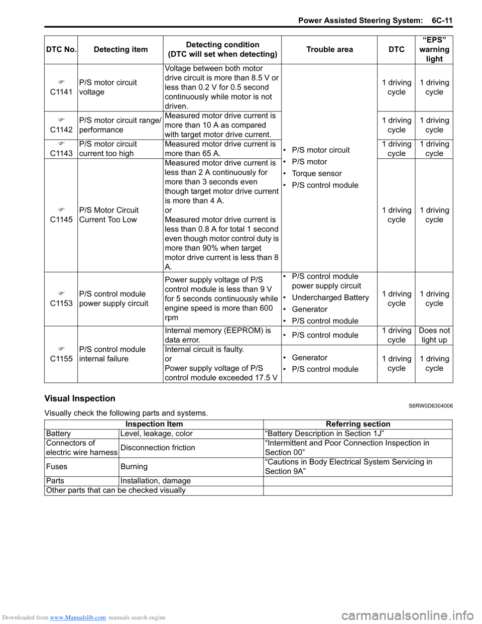
Visual InspectionS6RW0D6304006
Visually check the following parts and systems.�)
C1141P/S motor circuit
voltageVoltage between both motor
drive circuit is more than 8.5 V or
less than 0.2 V for 0.5 second
continuously while motor is not
driven.
• P/S motor circuit
• P/S motor
• Torque sensor
• P/S control module1 driving
cycle1 driving
cycle
�)
C1142P/S motor circuit range/
performanceMeasured motor drive current is
more than 10 A as compared
with target motor drive current.1 driving
cycle1 driving
cycle
�)
C1143P/S motor circuit
current too highMeasured motor drive current is
more than 65 A.1 driving
cycle1 driving
cycle
�)
C1145P/S Motor Circuit
Current Too Low Measured motor drive current is
less than 2 A continuously for
more than 3 seconds even
though target motor drive current
is more than 4 A.
or
Measured motor drive current is
less than 0.8 A for total 1 second
even though motor control duty is
more than 90% when target
motor drive current is less than 8
A.1 driving
cycle1 driving
cycle
�)
C1153P/S control module
power supply circuitPower supply voltage of P/S
control module is less than 9 V
for 5 seconds continuously while
engine speed is more than 600
rpm• P/S control module
power supply circuit
• Undercharged Battery
• Generator
• P/S control module1 driving
cycle1 driving
cycle
�)
C1155P/S control module
internal failureInternal memory (EEPROM) is
data error.• P/S control module1 driving
cycleDoes not
light up
Internal circuit is faulty.
or
Power supply voltage of P/S
control module exceeded 17.5 V• Generator
• P/S control module1 driving
cycle1 driving
cycle DTC No. Detecting itemDetecting condition
(DTC will set when detecting)Trouble area DTC“EPS”
warning
light
Inspection Item Referring section
Battery Level, leakage, color “Battery Description in Section 1J”
Connectors of
electric wire harnessDisconnection friction“Intermittent and Poor Connection Inspection in
Section 00”
Fuses Burning“Cautions in Body Electrical System Servicing in
Section 9A”
Parts Installation, damage
Other parts that can be checked visually
Page 907 of 1556

Downloaded from www.Manualslib.com manuals search engine Power Assisted Steering System: 6C-27
DTC Troubleshooting
DTC C1153: P/S Control Module Power Supply CircuitS6RW0D6304017
Wiring Diagram
DTC Detecting Condition and Trouble AreaStep Action Yes No
1Was “EPS System Check” performed?Go to Step 2. Go to “EPS System
Check”.
2DTC check
Is DTC C1153 and/or C1155 indicated, together?Go to applicable DTC
diag. flow.Go to Step 3.
3Power supply and ground circuit check
1) Check P/S control module power supply and ground
circuit referring to “P/S Control Module Power Supply
and Ground Circuit Check”.
Is it in good condition?Go to Step 4. Repair or replace
defective circuit.
4Motor circuit check
1) With ignition switch turned OFF, disconnect P/S control
module connector No.3 and P/S motor connector.
2) Check P/S control module connector and P/S motor
connector for proper connection.
3) If OK, check for open, short and/or high resistance in
motor circuit between P/S control module and P/S motor.
Refer to “Electrical Circuit Inspection Procedure in
Section 00”.
Are they in good condition?Go to Step 5. Repair motor circuit.
5P/S motor check
1) Check P/S motor referring to “P/S Motor and Its Circuit
Inspection”.
Is P/S motor in good condition?Substitute a known-
good P/S control
module and recheck.Replace the steering
gear case assembly and
recheck.
[A]
123
4567
8
9 11
10 12 13
141516
17 18 1920
1
2
[B]
LT GRN/
BLKE11-1E13-1 GRNGRN
WHT
5
3 6
8
9
7
4 12
12V
E13-2BLK
I6RW0C630009-01
[A]: P/S control module connector No.1 “E11” (viewed from harness side) 3. Junction block assembly 7. “IGN” fuse
[B]: P/S control module connector No.2 “E13” (viewed from harness side) 4. Main fuse 8. “P/S” fuse
1. Main fuse box 5. P/S control module 9. “IG1 SIG” fuse
2. Ignition switch 6. Individual circuit fuse box No.1
DTC detecting condition Trouble area
Power supply voltage of P/S control module is less than 9
V for 5 seconds continuously while engine speed is more
than 600 rpm.
(1 driving cycle detection logic)• P/S control module power supply circuit
• Battery
• Generator
• P/S control module
Page 908 of 1556

Downloaded from www.Manualslib.com manuals search engine 6C-28 Power Assisted Steering System:
DTC Troubleshooting
DTC C1155: P/S Control Module Internal FailureS6RW0D6304018
Wiring Diagram
Refer to “DTC C1153: P/S Control Module Power Supply Circuit”.
DTC Detecting Condition and Trouble Area
DTC TroubleshootingStep Action Yes No
1Was “EPS System Check” performed?Go to Step 2. Go to “EPS System
Check”.
2Battery voltage check
1) Check circuit fuse for P/S control module.
2) If OK, measure voltage between positive (+) battery
terminal and vehicle body ground with engine running.
Is voltage 10 V or more?Go to Step 3. Check charging system
referring to “Generator
Test (Undercharged
Battery Check) in
Section 1J”.
3P/S control module power supply circuit check
Check power supply circuit and ground circuit for P/S control
module referring to “P/S Control Module Power Supply and
Ground Circuit Check”.
Is check result in good condition?Substitute a known-
good P/S control
module and recheck.Repair defective circuit.
DTC detecting condition Trouble area
Internal memory (EEPROM) is data error.
(In this case, “EPS” warning light does not light up)
or
Internal circuit is faulty.
or
Power supply voltage of P/S control module exceeded
17.5 V
(1 driving cycle detection logic)• Generator
• P/S control module
Step Action Yes No
1Was “EPS System Check” performed?Go to Step 2. Go to “EPS System
Check”.
2P/S control module power supply and ground circuit
check
Check power supply circuit and ground circuit for P/S control
module referring to “P/S Control Module Power Supply and
Ground Circuit Check”.
Is check result in good condition?Go to Step 3. Repair or replace
defective circuit.
3Battery voltage check
1) Check voltage between positive (+) battery terminal and
vehicle body ground with engine speed at 3000 rpm.
Is voltage 15.5 V or less?Replace P/S control
module.Check charging system
referring to “Generator
Test (Overcharged
Battery Check) in
Section 1J”.
Page 1065 of 1556
Downloaded from www.Manualslib.com manuals search engine Air Bag System: 8B-26
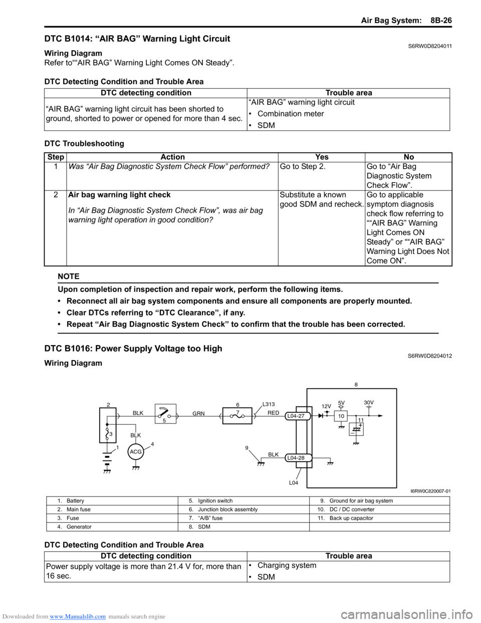
DTC B1014: “AIR BAG” Warning Light CircuitS6RW0D8204011
Wiring Diagram
Refer to““AIR BAG” Warning Light Comes ON Steady”.
DTC Detecting Condition and Trouble Area
DTC Troubleshooting
NOTE
Upon completion of inspection and repair work, perform the following items.
• Reconnect all air bag system components and ensure all components are properly mounted.
• Clear DTCs referring to “DTC Clearance”, if any.
• Repeat “Air Bag Diagnostic System Check” to confirm that the trouble has been corrected.
DTC B1016: Power Supply Voltage too HighS6RW0D8204012
Wiring Diagram
DTC Detecting Condition and Trouble AreaDTC detecting condition Trouble area
“AIR BAG” warning light circuit has been shorted to
ground, shorted to power or opened for more than 4 sec.“AIR BAG” warning light circuit
• Combination meter
•SDM
Step Action Yes No
1Was “Air Bag Diagnostic System Check Flow” performed?Go to Step 2. Go to “Air Bag
Diagnostic System
Check Flow”.
2Air bag warning light check
In “Air Bag Diagnostic System Check Flow”, was air bag
warning light operation in good condition?Substitute a known
good SDM and recheck.Go to applicable
symptom diagnosis
check flow referring to
““AIR BAG” Warning
Light Comes ON
Steady” or ““AIR BAG”
Warning Light Does Not
Come ON”.
BLK
L04
7
RED
GRN L313
98
L04-28
L04-27
1
2
3
BLK
45 BLK6
ACG
10
12V5V30V
11
I6RW0C820007-01
1. Battery 5. Ignition switch 9. Ground for air bag system
2. Main fuse 6. Junction block assembly 10. DC / DC converter
3. Fuse 7. “A/B” fuse 11. Back up capacitor
4. Generator 8. SDM
DTC detecting condition Trouble area
Power supply voltage is more than 21.4 V for, more than
16 sec.• Charging system
•SDM
Page 1066 of 1556
Downloaded from www.Manualslib.com manuals search engine 8B-27 Air Bag System:
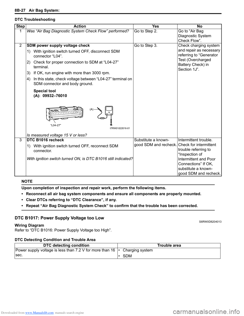
DTC Troubleshooting
NOTE
Upon completion of inspection and repair work, perform the following items.
• Reconnect all air bag system components and ensure all components are properly mounted.
• Clear DTCs referring to “DTC Clearance”, if any.
• Repeat “Air Bag Diagnostic System Check” to confirm that the trouble has been corrected.
DTC B1017: Power Supply Voltage too LowS6RW0D8204013
Wiring Diagram
Refer to “DTC B1016: Power Supply Voltage too High”.
DTC Detecting Condition and Trouble AreaStep Action Yes No
1Was “Air Bag Diagnostic System Check Flow” performed?Go to Step 2. Go to “Air Bag
Diagnostic System
Check Flow”.
2SDM power supply voltage check
1) With ignition switch turned OFF, disconnect SDM
connector “L04”.
2) Check for proper connection to SDM at “L04-27”
terminal.
3) If OK, run engine with more than 3000 rpm.
4) In this state, check voltage between “L04-27” terminal on
SDM connector and body ground.
Special tool
(A): 09932–76010
Is measured voltage 15 V or less?Go to Step 3. Check charging system
and repair as necessary
referring to “Generator
Test (Overcharged
Battery Check) in
Section 1J”.
3DTC B1016 recheck
1) With ignition switch turned OFF, reconnect SDM
connector.
With ignition switch turned ON, is DTC B1016 still indicated?Substitute a known-
good SDM and recheck.Intermittent trouble.
Check for intermittent
trouble referring to
“Inspection of
Intermittent and Poor
Connections” If OK,
substitute a known-
good SDM and recheck.
“L04-27”
(A)
I7RW01822016-01
DTC detecting condition Trouble area
Power supply voltage is less than 7.2 V for more than 16
sec.• Charging system
•SDM
Page 1124 of 1556
Downloaded from www.Manualslib.com manuals search engine 8B-85 Air Bag System:
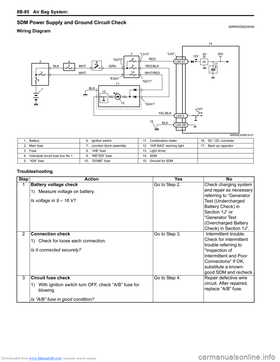
SDM Power Supply and Ground Circuit CheckS6RW0D8204049
Wiring Diagram
Troubleshooting
“L04”14
5
9RED
RED/BLK GRN
YEL/BLK
BLK
8 7
11
12
15
L04-2
L04-28
L04-27
“G241” “G271” “L313”
13
12V
6
1BLK
WHT WHT
WHT/RED 2
34
310 BLK
“G273”
“E324”16
12V5V30V
17
I6RW0C820016-01
1. Battery 6. Ignition switch 11. Combination meter 16. DC / DC converter
2. Main fuse 7. Junction block assembly 12. “AIR BAG” warning light 17. Back up capacitor
3. Fuse 8. “A/B” fuse 13. Light driver
4. Individual circuit fuse box No.1 9. “METER” fuse 14. SDM
5. “IGN” fuse 10. “DOME” fuse 15. Ground for SDM
Step Action Yes No
1Battery voltage check
1) Measure voltage on battery.
Is voltage in 9 – 16 V?Go to Step 2. Check charging system
and repair as necessary
referring to “Generator
Test (Undercharged
Battery Check) in
Section 1J” or
“Generator Test
(Overcharged Battery
Check) in Section 1J”.
2Connection check
1) Check for loose each connection.
Is it connected securely?Go to Step 3. Intermittent trouble.
Check for intermittent
trouble referring to
“Inspection of
Intermittent and Poor
Connections” If OK,
substitute a known-
good SDM and recheck.
3Circuit fuse check
1) With ignition switch turn OFF, check “A/B” fuse for
blowing.
Is “A/B” fuse in good condition?Go to Step 4. Repair defective wire
circuit. After repaired,
replace “A/B” fuse.
Page 1178 of 1556
Downloaded from www.Manualslib.com manuals search engine 9A-11 Wiring Systems:
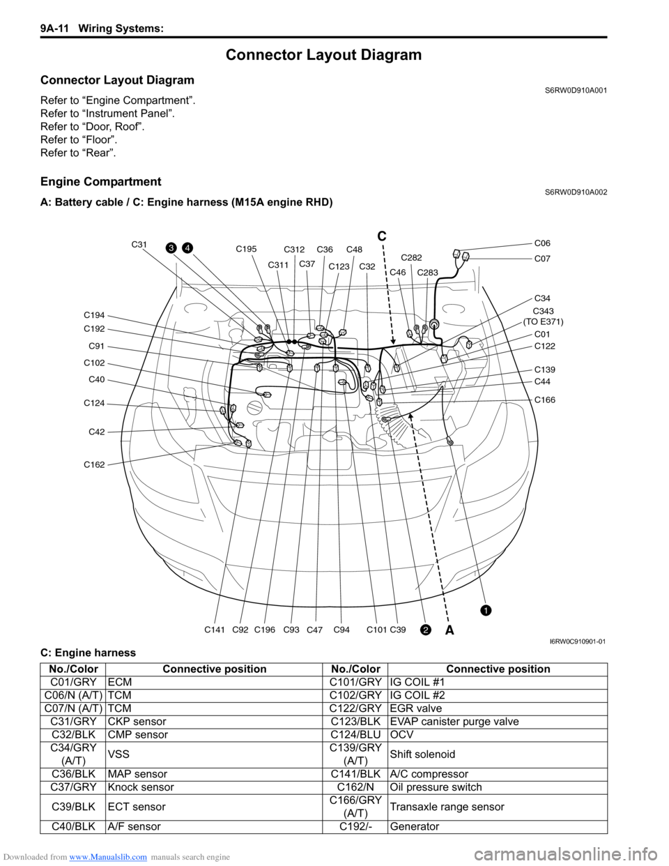
Connector Layout Diagram
Connector Layout DiagramS6RW0D910A001
Refer to “Engine Compartment”.
Refer to “Instrument Panel”.
Refer to “Door, Roof”.
Refer to “Floor”.
Refer to “Rear”.
Engine CompartmentS6RW0D910A002
A: Battery cable / C: Engine harness (M15A engine RHD)
C: Engine harness
C124
C40
C102
C91
C192
C194
C42
C162
C141C196
C195
C93C94C101C39C92
C31
C311C312
C36C48
C37C123
C47C32C282
C283
C343
(TO E371)
C01
C34
C07
C06
C122
C46
C139
C44
C166
43
2
1
C
A
I6RW0C910901-01
No./Color Connective position No./Color Connective position
C01/GRY ECM C101/GRY IG COIL #1
C06/N (A/T) TCM C102/GRY IG COIL #2
C07/N (A/T) TCM C122/GRY EGR valve
C31/GRY CKP sensor C123/BLK EVAP canister purge valve
C32/BLK CMP sensor C124/BLU OCV
C34/GRY
(A/T)VSSC139/GRY
(A/T)Shift solenoid
C36/BLK MAP sensor C141/BLK A/C compressor
C37/GRY Knock sensor C162/N Oil pressure switch
C39/BLK ECT sensorC166/GRY
(A/T)Transaxle range sensor
C40/BLK A/F sensor C192/- Generator