2006 SUZUKI SX4 charging
[x] Cancel search: chargingPage 1329 of 1556
Downloaded from www.Manualslib.com manuals search engine Lighting Systems: 9B-10
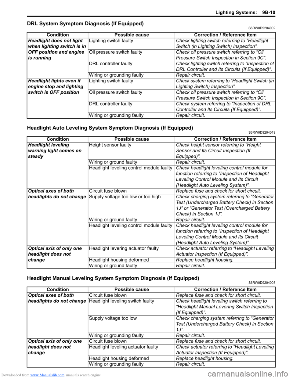
DRL System Symptom Diagnosis (If Equipped)S6RW0D9204002
Headlight Auto Leveling System Symptom Diagnosis (If Equipped)S6RW0D9204019
Headlight Manual Leveling System Symptom Diagnosis (If Equipped)S6RW0D9204003
Condition Possible cause Correction / Reference Item
Headlight does not light
when lighting switch is in
OFF position and engine
is runningLighting switch faultyCheck lighting switch referring to “Headlight
Switch (in Lighting Switch) Inspection”.
Oil pressure switch faultyCheck oil pressure switch referring to “Oil
Pressure Switch Inspection in Section 9C”.
DRL controller faultyCheck lighting switch referring to “Inspection of
DRL Controller and Its Circuits (If Equipped)”.
Wiring or grounding faultyRepair circuit.
Headlight lights even if
engine stop and lighting
switch is OFF positionLighting switch faultyCheck system referring to “Headlight Switch (in
Lighting Switch) Inspection”.
Oil pressure switch faultyCheck oil pressure switch referring to “Oil
Pressure Switch Inspection in Section 9C”.
DRL controller faultyCheck system referring to “Inspection of DRL
Controller and Its Circuits (If Equipped)”.
Wiring or grounding faultyRepair circuit.
Condition Possible cause Correction / Reference Item
Headlight leveling
warning light comes on
steadyHeight sensor faultyCheck height sensor referring to “Height
Sensor and Its Circuit Inspection (If
Equipped)”.
Wiring or ground faultyRepair circuit.
Headlight leveling control module faultyCheck headlight leveling control module for
function referring to “Inspection of Headlight
Leveling Control Module and Its Circuit
(Headlight Auto Leveling System)”.
Optical axes of both
headlights do not changeCircuit fuse blownReplace fuse and check for short circuit.
Supply voltage too low or too highCheck charging system referring to “Generator
Test (Undercharged Battery Check) in Section
1J” or “Generator Test (Overcharged Battery
Check) in Section 1J”.
Wiring or ground faultyRepair circuit.
Headlight leveling control module faultyCheck headlight leveling control module for
function referring to “Inspection of Headlight
Leveling Control Module and Its Circuit
(Headlight Auto Leveling System)”.
Optical axis of only one
headlight does not
changeHeadlight levering actuator faultyCheck actuator referring to “Headlight Leveling
Actuator Inspection (If Equipped)”.
Headlight housing deformedReplace headlight housing.
Wiring or ground faultyRepair circuit.
Condition Possible cause Correction / Reference Item
Optical axes of both
headlights do not changeCircuit fuse blownReplace fuse and check for short circuit.
Headlight leveling switch faultyCheck headlight leveling switch referring to
“Headlight Manual Levering Switch Inspection
(If Equipped)”.
Supply voltage too lowCheck charging system referring to “Generator
Test (Undercharged Battery Check) in Section
1J”.
Wiring or grounding faultyRepair circuit.
Optical axis of only one
headlight does not
changeCircuit fuse blownReplace fuse and check for short circuit.
Headlight leveling actuator faultyCheck actuator referring to “Headlight Leveling
Actuator Inspection (If Equipped)”.
Headlight housing deformedReplace headlight housing.
Wiring or grounding faultyRepair circuit.
Page 1330 of 1556
Downloaded from www.Manualslib.com manuals search engine 9B-11 Lighting Systems:
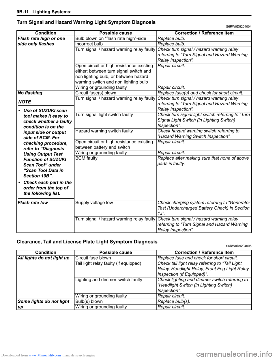
Turn Signal and Hazard Warning Light Symptom DiagnosisS6RW0D9204004
Clearance, Tail and License Plate Light Symptom DiagnosisS6RW0D9204005
Condition Possible cause Correction / Reference Item
Flash rate high or one
side only flashesBulb blown on “flash rate high”-sideReplace bulb.
Incorrect bulbReplace bulb.
Turn signal / hazard warning relay faultyCheck turn signal / hazard warning relay
referring to “Turn Signal and Hazard Warning
Relay Inspection”.
Open circuit or high resistance existing
either; between turn signal switch and
non lighting bulb, or between hazard
warning switch and non lighting bulbRepair circuit.
Wiring or grounding faultyRepair circuit.
No flashing
NOTE
• Use of SUZUKI scan
tool makes it easy to
check whether a faulty
condition is on the
input side or output
side of BCM. For
checking procedure,
refer to “Diagnosis
Using Output Test
Function of SUZUKI
Scan Tool” under
“Scan Tool Data in
Section 10B”.
• Check each part in the
order from the top of
the following list.
Circuit fuse(s) blownReplace fuse(s) and check for short circuit.
Turn signal / hazard warning relay faultyCheck turn signal / hazard warning relay
referring to “Turn Signal and Hazard Warning
Relay Inspection”.
Turn signal light switch faultyCheck turn signal light switch referring to “Turn
Signal Light Switch (in Lighting Switch)
Inspection”.
Hazard warning switch faultyCheck hazard warning switch referring to
“Hazard Warning Switch Inspection”.
Open circuit or high resistance existing
between battery and switchRepair circuit.
Wiring or grounding faultyRepair circuit.
BCM faultyReplace after making sure that none of above
parts is faulty.
Flash rate lowSupply voltage lowCheck charging system referring to “Generator
Test (Undercharged Battery Check) in Section
1J”.
Turn signal / hazard warning relay faultyCheck turn signal / hazard warning relay
referring to “Turn Signal and Hazard Warning
Relay Inspection”.
Condition Possible cause Correction / Reference Item
All lights do not light upCircuit fuse blownReplace fuse and check for short circuit.
Tail light relay faulty (if equipped)Check tail light relay referring to “Tail Light
Relay, Headlight Relay, Front Fog Light Relay
Inspection (If Equipped)”.
Lighting and dimmer switch faultyCheck lighting and dimmer switch referring to
“Headlight Switch (in Lighting Switch)
Inspection”.
Wiring or grounding faultyRepair circuit.
Some lights do not light
upBulb(s) blownReplace bulb(s).
Wiring or grounding faultyRepair circuit.
Page 1354 of 1556
Downloaded from www.Manualslib.com manuals search engine 9C-2 Instrumentation / Driver Info. / Horn:
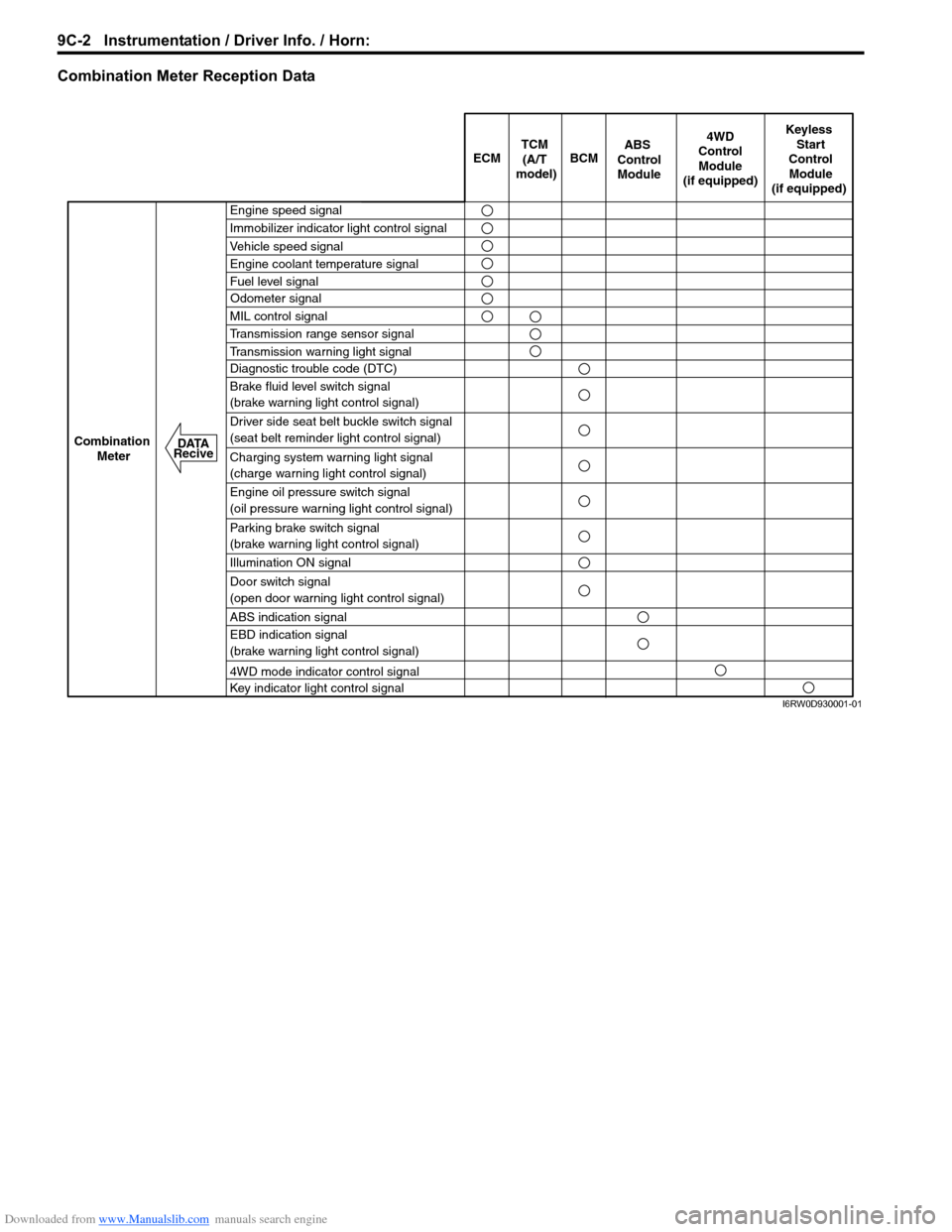
Combination Meter Reception Data
ECM BCM
Keyless
Start
Control
Module
(if equipped)
Combination
Meter4WD
Control
Module
(if equipped)TCM
(A/T
model)
Engine speed signal
Immobilizer indicator light control signal
Vehicle speed signal
Engine coolant temperature signal
Fuel level signal
MIL control signal
Transmission range sensor signal
Transmission warning light signal
Diagnostic trouble code (DTC)
Brake fluid level switch signal
(brake warning light control signal)
Driver side seat belt buckle switch signal
(seat belt reminder light control signal)
Charging system warning light signal
(charge warning light control signal)
Engine oil pressure switch signal
(oil pressure warning light control signal)
Parking brake switch signal
(brake warning light control signal)
Illumination ON signal
Door switch signal
(open door warning light control signal)
ABS indication signal
EBD indication signal
(brake warning light control signal)
4WD mode indicator control signal
Key indicator light control signal
ABS
Control
Module
Odometer signal
DATA
Recive
I6RW0D930001-01
Page 1361 of 1556
Downloaded from www.Manualslib.com manuals search engine Instrumentation / Driver Info. / Horn: 9C-9
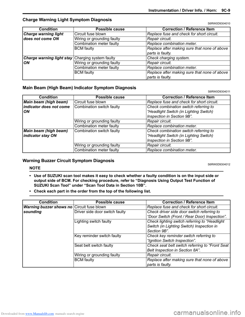
Charge Warning Light Symptom DiagnosisS6RW0D9304010
Main Beam (High Beam) Indicator Symptom DiagnosisS6RW0D9304011
Warning Buzzer Circuit Symptom DiagnosisS6RW0D9304012
NOTE
• Use of SUZUKI scan tool makes it easy to check whether a faulty condition is on the input side or
output side of BCM. For checking procedure, refer to “Diagnosis Using Output Test Function of
SUZUKI Scan Tool” under “Scan Tool Data in Section 10B”.
• Check each part in the order from the top of the following list.
Condition Possible cause Correction / Reference Item
Charge warning light
does not come ONCircuit fuse blownReplace fuse and check for short circuit.
Wiring or grounding faultyRepair circuit.
Combination meter faultyReplace combination meter.
BCM faulty Replace after making sure that none of above
parts is faulty.
Charge warning light stay
ONCharging system faultyCheck charging system.
Wiring or grounding faultyRepair circuit.
Combination meter faultyReplace combination meter.
BCM faulty Replace after making sure that none of above
parts is faulty.
Condition Possible cause Correction / Reference Item
Main beam (high beam)
indicator does not come
ONCircuit fuse blownReplace fuse and check for short circuit.
Combination switch faultyCheck combination switch referring to
“Headlight Switch (in Lighting Switch)
Inspection in Section 9B”.
Wiring or grounding faultyRepair circuit.
Combination meter faultyReplace combination meter.
Main beam (high beam)
indicator stay ONCombination switch faultyCheck combination switch referring to
“Headlight Switch (in Lighting Switch)
Inspection in Section 9B”.
Wiring or grounding faultyRepair circuit.
Combination meter faultyReplace combination meter.
Condition Possible cause Correction / Reference Item
Warning buzzer shows no
soundingCircuit fuse blownReplace fuse and check for short circuit.
Driver side door switch faultyCheck driver side door switch referring to
“Door Switch (Front / Rear Door) Inspection”.
Lighting switch faultyCheck lighting switch referring to “Headlight
Switch (in Lighting Switch) Inspection in
Section 9B”.
Key reminder switch faultyCheck key reminder switch referring to
“Ignition Switch Inspection”.
Seat belt switch faultyCheck seat belt switch referring to “Front Seat
Belt Inspection in Section 8A”.
Wiring or grounding faultyRepair circuit.
BCM faultyReplace after making sure that none of above
parts is faulty.
Page 1474 of 1556
Downloaded from www.Manualslib.com manuals search engine 10B-1 Body Electrical Control System:
Control Systems
Body Electrical Control System
Precautions
Precautions in Diagnosing TroubleS6RW0DA200001
• Diagnostic information stored in BCM memory can be cleared as well as checked by using SUZUKI scan tool.
Before using scan tool, read its Operator’s (Instruction) Manual carefully to have good understanding as to what
functions are available and how to use it.
• Be sure to read “Precautions for Electrical Circuit Service in Section 00” before inspection and observe what is
written there.
• Communication of ECM, TCM (A/T model), ABS control module, 4WD control module (if equipped), keyless start
control module (if equipped), combination meter and BCM is established by CAN (Controller Area Network). For
detail of CAN communication for BCM, refer to “CAN Communication System Description”. Therefore, handle CAN
communication line with care referring to “Precaution for CAN Communication System in Section 00”.
General Description
BCM General DescriptionS6RW0DA201001
The Body electrical Control Module (BCM) is
incorporated in junction block. Do not attempt removal of
BCM from junction block as it may cause contact failure.
The BCM incorporates relays and controllers which are
used for the following systems and controls them.
• Power door lock (if equipped)
• Keyless entry (if equipped)
• Door lock function of keyless start system (if
equipped)
• Rear wiper
• Combination meter
• Interior light• Warning buzzer
• Rear end door window defogger and door mirror
heater (if equipped)
• Rear end door opener (if equipped)
• Theft deterrent light
Also, the BCM has a function to cause the interior light
and open door warning light in the combination meter to
turn off when any door is left open for longer than 15
minutes to reduce wasteful battery consumption.
In addition, it is possible to check operation of actuator
which is controlled by BCM by using the output test
function of SUZUKI scan tool to operate actuator
simulatively.
CAN Communication System DescriptionS6RW0DA201002
Refer to “CAN Communication System Description in Section 1A” for CAN communication system description.
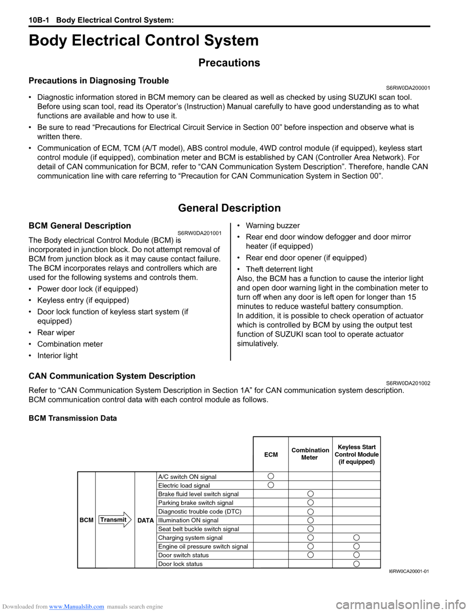
BCM communication control data with each control module as follows.
BCM Transmission Data
A/C switch ON signal
Electric load signal
Brake fluid level switch signal
Parking brake switch signal
Diagnostic trouble code (DTC)
Illumination ON signal
Seat belt buckle switch signal
Charging system signal
Engine oil pressure switch signal
Door switch status
Door lock statusECMKeyless Start
Control Module
(if equipped) Combination
Meter
BCMTransmit
DATA
I6RW0CA20001-01
Page 1490 of 1556
Downloaded from www.Manualslib.com manuals search engine 10B-17 Body Electrical Control System:
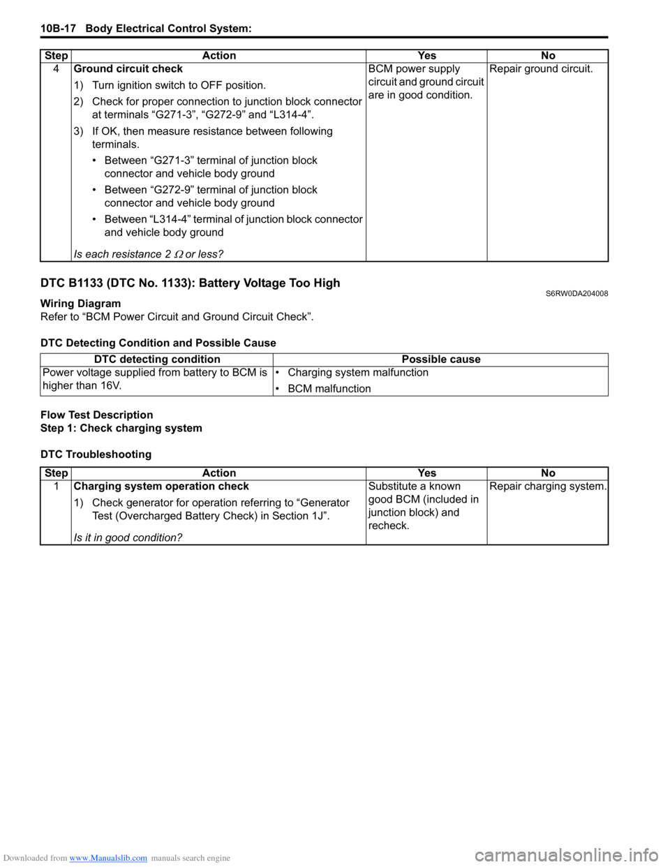
DTC B1133 (DTC No. 1133): Battery Voltage Too HighS6RW0DA204008
Wiring Diagram
Refer to “BCM Power Circuit and Ground Circuit Check”.
DTC Detecting Condition and Possible Cause
Flow Test Description
Step 1: Check charging system
DTC Troubleshooting4Ground circuit check
1) Turn ignition switch to OFF position.
2) Check for proper connection to junction block connector
at terminals “G271-3”, “G272-9” and “L314-4”.
3) If OK, then measure resistance between following
terminals.
• Between “G271-3” terminal of junction block
connector and vehicle body ground
• Between “G272-9” terminal of junction block
connector and vehicle body ground
• Between “L314-4” terminal of junction block connector
and vehicle body ground
Is each resistance 2
Ω or less?BCM power supply
circuit and ground circuit
are in good condition.Repair ground circuit. Step Action Yes No
DTC detecting condition Possible cause
Power voltage supplied from battery to BCM is
higher than 16V.• Charging system malfunction
• BCM malfunction
Step Action Yes No
1Charging system operation check
1) Check generator for operation referring to “Generator
Test (Overcharged Battery Check) in Section 1J”.
Is it in good condition?Substitute a known
good BCM (included in
junction block) and
recheck.Repair charging system.
Page 1529 of 1556
Downloaded from www.Manualslib.com manuals search engine Keyless Start System: 10E-7
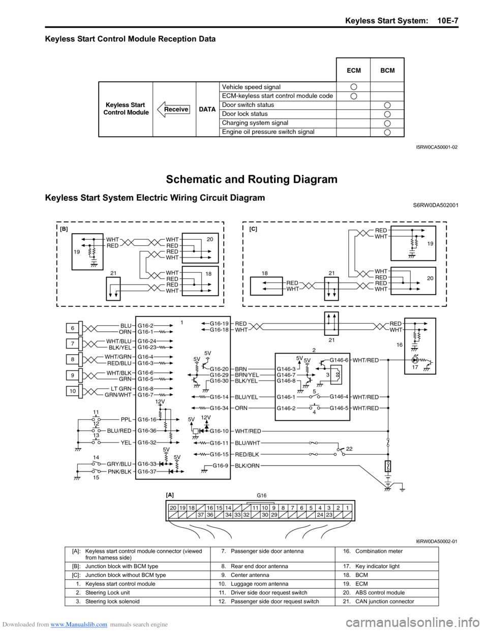
Keyless Start Control Module Reception Data
Schematic and Routing Diagram
Keyless Start System Electric Wiring Circuit DiagramS6RW0DA502001
Vehicle speed signal
ECM-keyless start control module code
Door switch status
Door lock status
Charging system signal
Engine oil pressure switch signalECM BCM
DATA
ReceiveKeyless Start
Control Module
I5RW0CA50001-02
BLK/ORNG16-9
G16-15
G16-14
G16-37G16-33
G16-16
G16-20G16-29G16-30
G16-36
G16-32
G16-10
G16-34
G16-11BLU/WHT
WHT/RED
WHT/RED
PNK/BLKGRY/BLU
BLU/RED
YEL
PPL
RED/BLK
5V5V 5V5V
5V5V
5V12V 12V
G16-2G16-1BLU
ORNWHTREDWHTREDG16-18G16-19
BLU/YEL
ORN
G16-24G16-23
BLK/YEL WHT/BLU
G16-7
GRN/WHTLT GRNG16-8
G16-5G16-6
GRN WHT/BLK
G16-4G16-3 WHT/GRN
RED/BLU
BLK/YELBRN/YELBRNG146-3
G146-1
G146-2G146-5
G146-4
G146-6
G146-7G146-8
WHT/RED
WHT/RED
G16[A]
1 2 3 4 5 6 7 8 9 10 11 14 15 16
36 34 33 32 30 29 24 23 37 18 19 20
WHTRED
WHT
WHT
RED
RED
WHTRED
6
7
8
9
10
11
12
13
14
15118
21
21
2
3
5
419
20
16
17
22
WHTRED
WHTREDWHTRED
18 1920WHTRED
WHTRED
21
[B][C]
I6RW0DA50002-01
[A]: Keyless start control module connector (viewed
from harness side)7. Passenger side door antenna 16. Combination meter
[B]: Junction block with BCM type 8. Rear end door antenna 17. Key indicator light
[C]: Junction block without BCM type 9. Center antenna 18. BCM
1. Keyless start control module 10. Luggage room antenna 19. ECM
2. Steering Lock unit 11. Driver side door request switch 20. ABS control module
3. Steering lock solenoid 12. Passenger side door request switch 21. CAN junction connector