2006 SUZUKI SX4 charging
[x] Cancel search: chargingPage 977 of 1556

Downloaded from www.Manualslib.com manuals search engine Air Conditioning System: Manual Type 7B-37
Specifications
Tightening Torque SpecificationsS6RW0D7217001
NOTE
The specified tightening torque is also described in the following.
“A/C System Major Components Location”
“Compressor Assembly Components”
Reference:
For the tightening torque of fastener not specified in this section, refer to “Fasteners Information in Section 0A”.
Special Tools and Equipment
Recommended Service MaterialS6RW0D7218001
NOTE
Required service material is also described in the following.
“HVAC Unit Components”
“Compressor Assembly Components”
Special ToolS6RW0D7218002
Fastening partTightening torque
Note
N⋅mkgf-mlb-ft
Expansion valve bolt 4.5 0.45 3.5�)
A/C refrigerant pressure sensor 11 1.1 8.0�)
Compressor mounting bolt 25 2.5 18.0�)
Armature plate nut 16 1.6 11.5�)
Relief valve 8 0.8 6.0�)
Material SUZUKI recommended product or Specification Note
Compressor oil MATSUSHITADENKI GU10 P/No.: 99000–99015–
00A�)
Silicon sealant SUZUKI SILICON SEALANT KE-
347W (100g)P/No.: 99000–34220�)
09900–06107 09990–06020
Snap ring pliers (opening
type)Manifold gauge set (R134a)
�) / �) / �) / �) / �)1.Manifold gauge
2.Charging hoses 3.Quick
connector 4.Refrigerant
container tap valve
5.Refrigerant container T
joint 6.Packing sets 7.Case
�)
09990–86012 09991–06310
Gas leak detector Armature plate holder
This kit includes following
items.1. Gas leak detector,
2. Instruction manual, 3.
Filter, 4. Sensor, 5. Dri-sell
battery (size D) �) / �)�) / �)
12
34
5
Page 1053 of 1556
Downloaded from www.Manualslib.com manuals search engine Air Bag System: 8B-14
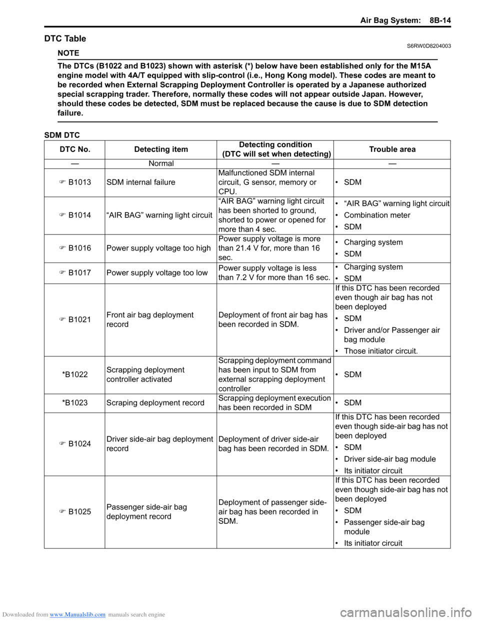
DTC TableS6RW0D8204003
NOTE
The DTCs (B1022 and B1023) shown with asterisk (*) below have been established only for the M15A
engine model with 4A/T equipped with slip-control (i.e., Hong Kong model). These codes are meant to
be recorded when External Scrapping Deployment Controller is operated by a Japanese authorized
special scrapping trader. Therefore, normally these codes will not appear outside Japan. However,
should these codes be detected, SDM must be replaced because the cause is due to SDM detection
failure.
SDM DTC
DTC No. Detecting itemDetecting condition
(DTC will set when detecting)Trouble area
—Normal — —
�) B1013 SDM internal failureMalfunctioned SDM internal
circuit, G sensor, memory or
CPU.•SDM
�) B1014 “AIR BAG” warning light circuit“AIR BAG” warning light circuit
has been shorted to ground,
shorted to power or opened for
more than 4 sec.• “AIR BAG” warning light circuit
• Combination meter
•SDM
�) B1016 Power supply voltage too highPower supply voltage is more
than 21.4 V for, more than 16
sec.• Charging system
•SDM
�) B1017 Power supply voltage too lowPower supply voltage is less
than 7.2 V for more than 16 sec.• Charging system
•SDM
�) B1021Front air bag deployment
recordDeployment of front air bag has
been recorded in SDM.If this DTC has been recorded
even though air bag has not
been deployed
•SDM
• Driver and/or Passenger air
bag module
• Those initiator circuit.
*B1022Scrapping deployment
controller activatedScrapping deployment command
has been input to SDM from
external scrapping deployment
controller•SDM
*B1023 Scraping deployment recordScrapping deployment execution
has been recorded in SDM•SDM
�) B1024Driver side-air bag deployment
recordDeployment of driver side-air
bag has been recorded in SDM.If this DTC has been recorded
even though side-air bag has not
been deployed
•SDM
• Driver side-air bag module
• Its initiator circuit
�) B1025Passenger side-air bag
deployment recordDeployment of passenger side-
air bag has been recorded in
SDM.If this DTC has been recorded
even though side-air bag has not
been deployed
•SDM
• Passenger side-air bag
module
• Its initiator circuit
Page 1065 of 1556
Downloaded from www.Manualslib.com manuals search engine Air Bag System: 8B-26
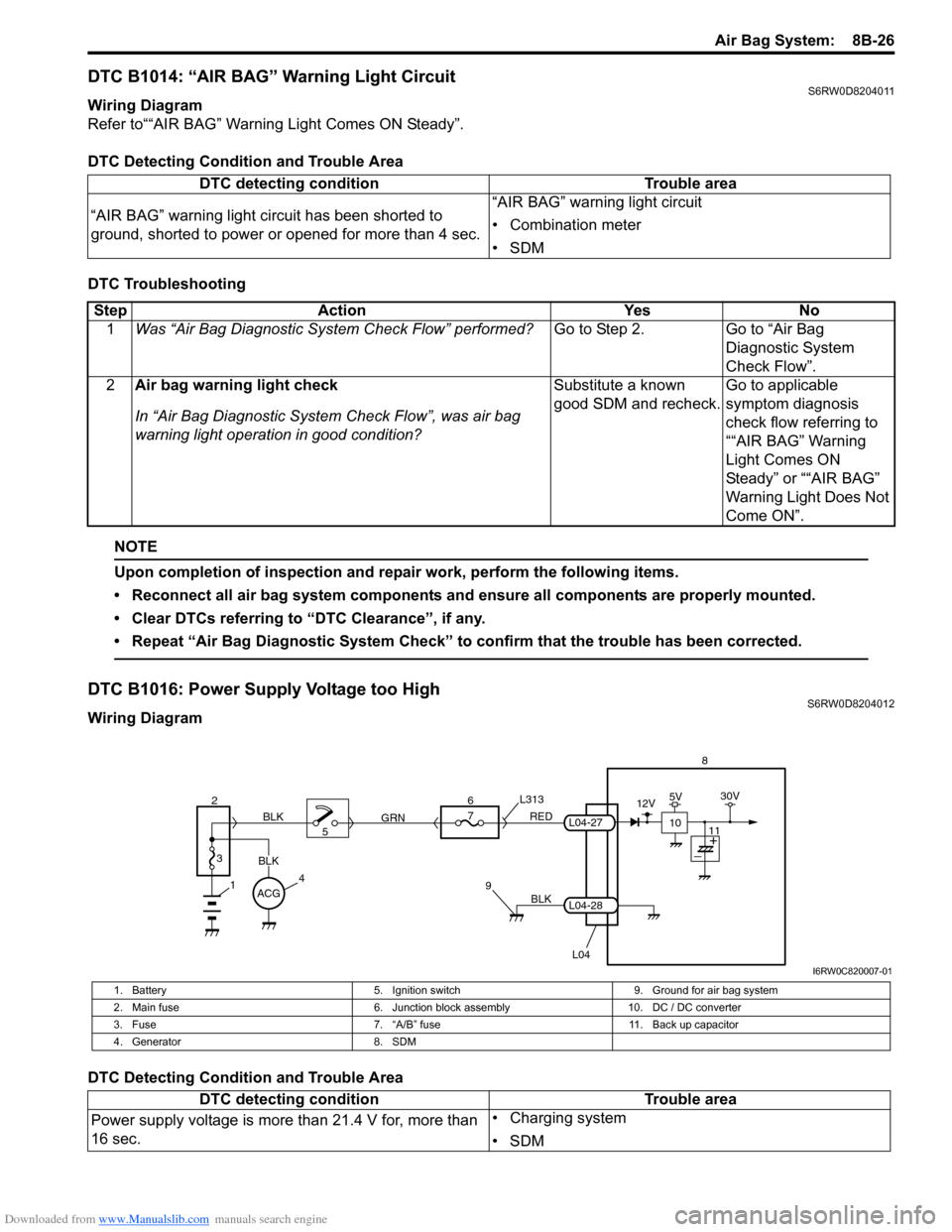
DTC B1014: “AIR BAG” Warning Light CircuitS6RW0D8204011
Wiring Diagram
Refer to““AIR BAG” Warning Light Comes ON Steady”.
DTC Detecting Condition and Trouble Area
DTC Troubleshooting
NOTE
Upon completion of inspection and repair work, perform the following items.
• Reconnect all air bag system components and ensure all components are properly mounted.
• Clear DTCs referring to “DTC Clearance”, if any.
• Repeat “Air Bag Diagnostic System Check” to confirm that the trouble has been corrected.
DTC B1016: Power Supply Voltage too HighS6RW0D8204012
Wiring Diagram
DTC Detecting Condition and Trouble AreaDTC detecting condition Trouble area
“AIR BAG” warning light circuit has been shorted to
ground, shorted to power or opened for more than 4 sec.“AIR BAG” warning light circuit
• Combination meter
•SDM
Step Action Yes No
1Was “Air Bag Diagnostic System Check Flow” performed?Go to Step 2. Go to “Air Bag
Diagnostic System
Check Flow”.
2Air bag warning light check
In “Air Bag Diagnostic System Check Flow”, was air bag
warning light operation in good condition?Substitute a known
good SDM and recheck.Go to applicable
symptom diagnosis
check flow referring to
““AIR BAG” Warning
Light Comes ON
Steady” or ““AIR BAG”
Warning Light Does Not
Come ON”.
BLK
L04
7
RED
GRN L313
98
L04-28
L04-27
1
2
3
BLK
45 BLK6
ACG
10
12V5V30V
11
I6RW0C820007-01
1. Battery 5. Ignition switch 9. Ground for air bag system
2. Main fuse 6. Junction block assembly 10. DC / DC converter
3. Fuse 7. “A/B” fuse 11. Back up capacitor
4. Generator 8. SDM
DTC detecting condition Trouble area
Power supply voltage is more than 21.4 V for, more than
16 sec.• Charging system
•SDM
Page 1066 of 1556
Downloaded from www.Manualslib.com manuals search engine 8B-27 Air Bag System:
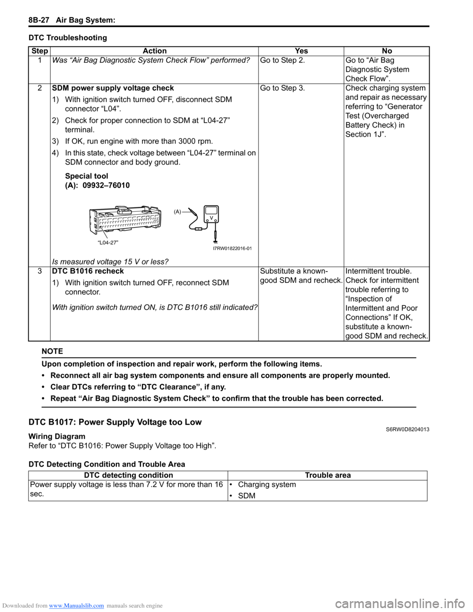
DTC Troubleshooting
NOTE
Upon completion of inspection and repair work, perform the following items.
• Reconnect all air bag system components and ensure all components are properly mounted.
• Clear DTCs referring to “DTC Clearance”, if any.
• Repeat “Air Bag Diagnostic System Check” to confirm that the trouble has been corrected.
DTC B1017: Power Supply Voltage too LowS6RW0D8204013
Wiring Diagram
Refer to “DTC B1016: Power Supply Voltage too High”.
DTC Detecting Condition and Trouble AreaStep Action Yes No
1Was “Air Bag Diagnostic System Check Flow” performed?Go to Step 2. Go to “Air Bag
Diagnostic System
Check Flow”.
2SDM power supply voltage check
1) With ignition switch turned OFF, disconnect SDM
connector “L04”.
2) Check for proper connection to SDM at “L04-27”
terminal.
3) If OK, run engine with more than 3000 rpm.
4) In this state, check voltage between “L04-27” terminal on
SDM connector and body ground.
Special tool
(A): 09932–76010
Is measured voltage 15 V or less?Go to Step 3. Check charging system
and repair as necessary
referring to “Generator
Test (Overcharged
Battery Check) in
Section 1J”.
3DTC B1016 recheck
1) With ignition switch turned OFF, reconnect SDM
connector.
With ignition switch turned ON, is DTC B1016 still indicated?Substitute a known-
good SDM and recheck.Intermittent trouble.
Check for intermittent
trouble referring to
“Inspection of
Intermittent and Poor
Connections” If OK,
substitute a known-
good SDM and recheck.
“L04-27”
(A)
I7RW01822016-01
DTC detecting condition Trouble area
Power supply voltage is less than 7.2 V for more than 16
sec.• Charging system
•SDM
Page 1124 of 1556
Downloaded from www.Manualslib.com manuals search engine 8B-85 Air Bag System:
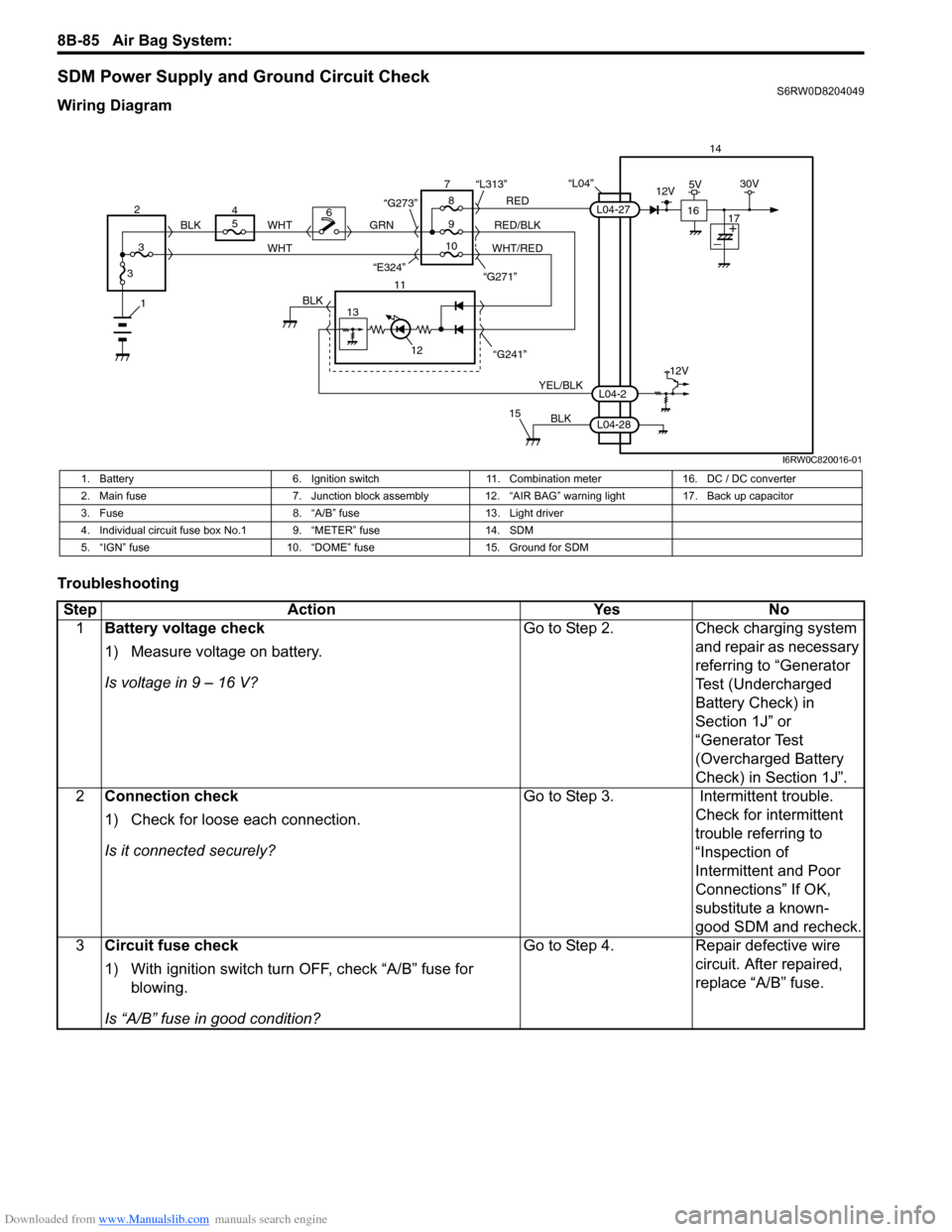
SDM Power Supply and Ground Circuit CheckS6RW0D8204049
Wiring Diagram
Troubleshooting
“L04”14
5
9RED
RED/BLK GRN
YEL/BLK
BLK
8 7
11
12
15
L04-2
L04-28
L04-27
“G241” “G271” “L313”
13
12V
6
1BLK
WHT WHT
WHT/RED 2
34
310 BLK
“G273”
“E324”16
12V5V30V
17
I6RW0C820016-01
1. Battery 6. Ignition switch 11. Combination meter 16. DC / DC converter
2. Main fuse 7. Junction block assembly 12. “AIR BAG” warning light 17. Back up capacitor
3. Fuse 8. “A/B” fuse 13. Light driver
4. Individual circuit fuse box No.1 9. “METER” fuse 14. SDM
5. “IGN” fuse 10. “DOME” fuse 15. Ground for SDM
Step Action Yes No
1Battery voltage check
1) Measure voltage on battery.
Is voltage in 9 – 16 V?Go to Step 2. Check charging system
and repair as necessary
referring to “Generator
Test (Undercharged
Battery Check) in
Section 1J” or
“Generator Test
(Overcharged Battery
Check) in Section 1J”.
2Connection check
1) Check for loose each connection.
Is it connected securely?Go to Step 3. Intermittent trouble.
Check for intermittent
trouble referring to
“Inspection of
Intermittent and Poor
Connections” If OK,
substitute a known-
good SDM and recheck.
3Circuit fuse check
1) With ignition switch turn OFF, check “A/B” fuse for
blowing.
Is “A/B” fuse in good condition?Go to Step 4. Repair defective wire
circuit. After repaired,
replace “A/B” fuse.
Page 1161 of 1556
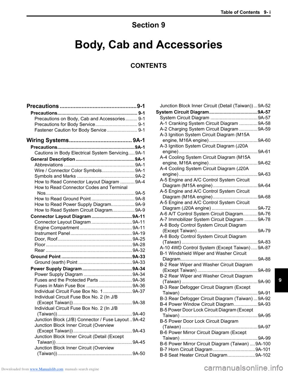
Downloaded from www.Manualslib.com manuals search engine Table of Contents 9- i
9
Section 9
CONTENTS
Body, Cab and Accessories
Precautions ................................................. 9-1
Precautions............................................................. 9-1
Precautions on Body, Cab and Accessories ......... 9-1
Precautions for Body Service ................................ 9-1
Fastener Caution for Body Service ....................... 9-1
Wiring Systems........................................ 9A-1
Precautions........................................................... 9A-1
Cautions in Body Electrical System Servicing..... 9A-1
General Description ............................................. 9A-1
Abbreviations ...................................................... 9A-1
Wire / Connector Color Symbols ......................... 9A-1
Symbols and Marks ............................................ 9A-2
How to Read Connector Layout Diagram ........... 9A-4
How to Read Connector Codes and Terminal
Nos.................................................................... 9A-5
How to Read Ground Point ................................. 9A-8
How to Read Power Supply Diagram.................. 9A-9
How to Read System Circuit Diagram................. 9A-9
Connector Layout Diagram ............................... 9A-11
Connector Layout Diagram ............................... 9A-11
Engine Compartment ........................................ 9A-11
Instrument Panel ............................................... 9A-19
Door, Roof......................................................... 9A-25
Floor .................................................................. 9A-28
Rear .................................................................. 9A-32
Ground Point ...................................................... 9A-33
Ground (earth) Point ......................................... 9A-33
Power Supply Diagram ...................................... 9A-34
Power Supply Diagram ..................................... 9A-34
Fuses and the Protected Parts ......................... 9A-36
Fuses in Main Fuse Box ................................... 9A-36
Individual Circuit Fuse Box No. 1 ...................... 9A-37
Individual Circuit Fuse Box No. 2 (In J/B
(Except Taiwan)) ............................................. 9A-38
Individual Circuit Fuse Box No. 2 (In J/B
(Taiwan)) ......................................................... 9A-40
Junction Block (J/B) Connector / Fuse Layout .. 9A-42
Junction Block Inner Circuit (Overview
(Except Taiwan)) ............................................. 9A-43
Junction Block Inner Circuit (Detail (Except
Taiwan)) .......................................................... 9A-45
Junction Block Inner Circuit (Overview
(Taiwan)) ......................................................... 9A-50Junction Block Inner Circuit (Detail (Taiwan)) ... 9A-52
System Circuit Diagram.....................................9A-57
System Circuit Diagram .................................... 9A-57
A-1 Cranking System Circuit Diagram .............. 9A-58
A-2 Charging System Circuit Diagram .............. 9A-59
A-3 Ignition System Circuit Diagram (M15A
engine, M16A engine) ..................................... 9A-60
A-3 Ignition System Circuit Diagram (J20A
engine) ............................................................ 9A-61
A-4 Cooling System Circuit Diagram (M15A
engine, M16A engine) ..................................... 9A-62
A-4 Cooling System Circuit Diagram (J20A
engine) ............................................................ 9A-63
A-5 Engine and A/C Control System Circuit
Diagram (M15A engine) .................................. 9A-64
A-5 Engine and A/C Control System Circuit
Diagram (M16A engine) .................................. 9A-68
A-5 Engine and A/C Control System Circuit
Diagram (J20A engine) ................................... 9A-72
A-6 A/T Control System Circuit Diagram........... 9A-76
A-7 Immobilizer System Circuit Diagram .......... 9A-78
A-8 Body Control System Circuit Diagram
(Except Taiwan) .............................................. 9A-79
A-8 Body Control System Circuit Diagram
(Taiwan) .......................................................... 9A-83
A-10 4WD Control System (Except Taiwan) ..... 9A-87
B-1 Windshield Wiper and Washer Circuit
Diagram........................................................... 9A-88
B-2 Rear Wiper and Washer Circuit Diagram
(Except Taiwan) .............................................. 9A-89
B-2 Rear Wiper and Washer Circuit Diagram
(Taiwan) .......................................................... 9A-90
B-3 Rear Defogger Circuit Diagram (Except
Taiwan) ........................................................... 9A-91
B-3 Rear Defogger Circuit Diagram (Taiwan) ... 9A-92
B-4 Power Window Circuit Diagram .................. 9A-93
B-5 Power Door Lock Circuit Diagram (Except
Taiwan) ........................................................... 9A-95
B-5 Power Door Lock Circuit Diagram
(Taiwan) .......................................................... 9A-97
B-6 Power Mirror Circuit Diagram (Except
Taiwan) ........................................................... 9A-99
B-6 Power Mirror Circuit Diagram (Taiwan) .... 9A-100
B-7 Horn Circuit Diagram ................................ 9A-101
B-8 Seat Heater Circuit Diagram..................... 9A-102
Page 1224 of 1556
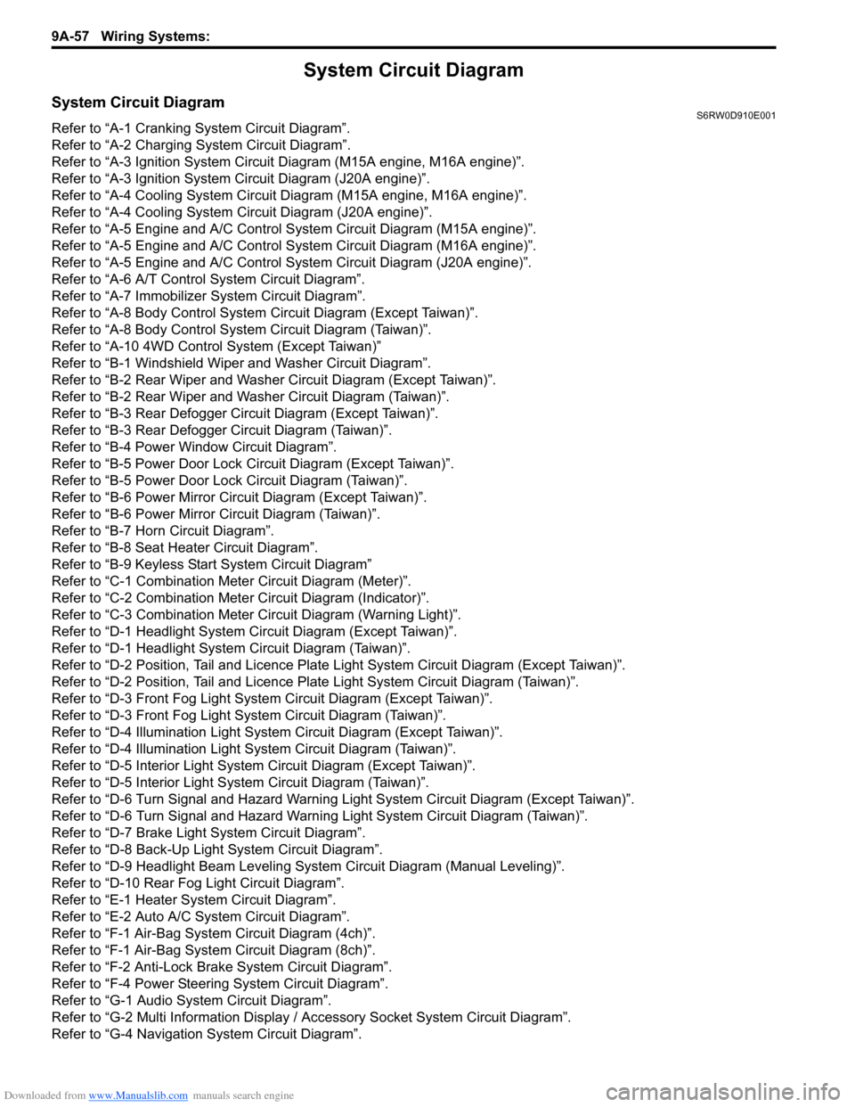
Downloaded from www.Manualslib.com manuals search engine 9A-57 Wiring Systems:
System Circuit Diagram
System Circuit DiagramS6RW0D910E001
Refer to “A-1 Cranking System Circuit Diagram”.
Refer to “A-2 Charging System Circuit Diagram”.
Refer to “A-3 Ignition System Circuit Diagram (M15A engine, M16A engine)”.
Refer to “A-3 Ignition System Circuit Diagram (J20A engine)”.
Refer to “A-4 Cooling System Circuit Diagram (M15A engine, M16A engine)”.
Refer to “A-4 Cooling System Circuit Diagram (J20A engine)”.
Refer to “A-5 Engine and A/C Control System Circuit Diagram (M15A engine)”.
Refer to “A-5 Engine and A/C Control System Circuit Diagram (M16A engine)”.
Refer to “A-5 Engine and A/C Control System Circuit Diagram (J20A engine)”.
Refer to “A-6 A/T Control System Circuit Diagram”.
Refer to “A-7 Immobilizer System Circuit Diagram”.
Refer to “A-8 Body Control System Circuit Diagram (Except Taiwan)”.
Refer to “A-8 Body Control System Circuit Diagram (Taiwan)”.
Refer to “A-10 4WD Control System (Except Taiwan)”
Refer to “B-1 Windshield Wiper and Washer Circuit Diagram”.
Refer to “B-2 Rear Wiper and Washer Circuit Diagram (Except Taiwan)”.
Refer to “B-2 Rear Wiper and Washer Circuit Diagram (Taiwan)”.
Refer to “B-3 Rear Defogger Circuit Diagram (Except Taiwan)”.
Refer to “B-3 Rear Defogger Circuit Diagram (Taiwan)”.
Refer to “B-4 Power Window Circuit Diagram”.
Refer to “B-5 Power Door Lock Circuit Diagram (Except Taiwan)”.
Refer to “B-5 Power Door Lock Circuit Diagram (Taiwan)”.
Refer to “B-6 Power Mirror Circuit Diagram (Except Taiwan)”.
Refer to “B-6 Power Mirror Circuit Diagram (Taiwan)”.
Refer to “B-7 Horn Circuit Diagram”.
Refer to “B-8 Seat Heater Circuit Diagram”.
Refer to “B-9 Keyless Start System Circuit Diagram”
Refer to “C-1 Combination Meter Circuit Diagram (Meter)”.
Refer to “C-2 Combination Meter Circuit Diagram (Indicator)”.
Refer to “C-3 Combination Meter Circuit Diagram (Warning Light)”.
Refer to “D-1 Headlight System Circuit Diagram (Except Taiwan)”.
Refer to “D-1 Headlight System Circuit Diagram (Taiwan)”.
Refer to “D-2 Position, Tail and Licence Plate Light System Circuit Diagram (Except Taiwan)”.
Refer to “D-2 Position, Tail and Licence Plate Light System Circuit Diagram (Taiwan)”.
Refer to “D-3 Front Fog Light System Circuit Diagram (Except Taiwan)”.
Refer to “D-3 Front Fog Light System Circuit Diagram (Taiwan)”.
Refer to “D-4 Illumination Light System Circuit Diagram (Except Taiwan)”.
Refer to “D-4 Illumination Light System Circuit Diagram (Taiwan)”.
Refer to “D-5 Interior Light System Circuit Diagram (Except Taiwan)”.
Refer to “D-5 Interior Light System Circuit Diagram (Taiwan)”.
Refer to “D-6 Turn Signal and Hazard Warning Light System Circuit Diagram (Except Taiwan)”.
Refer to “D-6 Turn Signal and Hazard Warning Light System Circuit Diagram (Taiwan)”.
Refer to “D-7 Brake Light System Circuit Diagram”.
Refer to “D-8 Back-Up Light System Circuit Diagram”.
Refer to “D-9 Headlight Beam Leveling System Circuit Diagram (Manual Leveling)”.
Refer to “D-10 Rear Fog Light Circuit Diagram”.
Refer to “E-1 Heater System Circuit Diagram”.
Refer to “E-2 Auto A/C System Circuit Diagram”.
Refer to “F-1 Air-Bag System Circuit Diagram (4ch)”.
Refer to “F-1 Air-Bag System Circuit Diagram (8ch)”.
Refer to “F-2 Anti-Lock Brake System Circuit Diagram”.
Refer to “F-4 Power Steering System Circuit Diagram”.
Refer to “G-1 Audio System Circuit Diagram”.
Refer to “G-2 Multi Information Display / Accessory Socket System Circuit Diagram”.
Refer to “G-4 Navigation System Circuit Diagram”.
Page 1226 of 1556
Downloaded from www.Manualslib.com manuals search engine 9A-59 Wiring Systems:
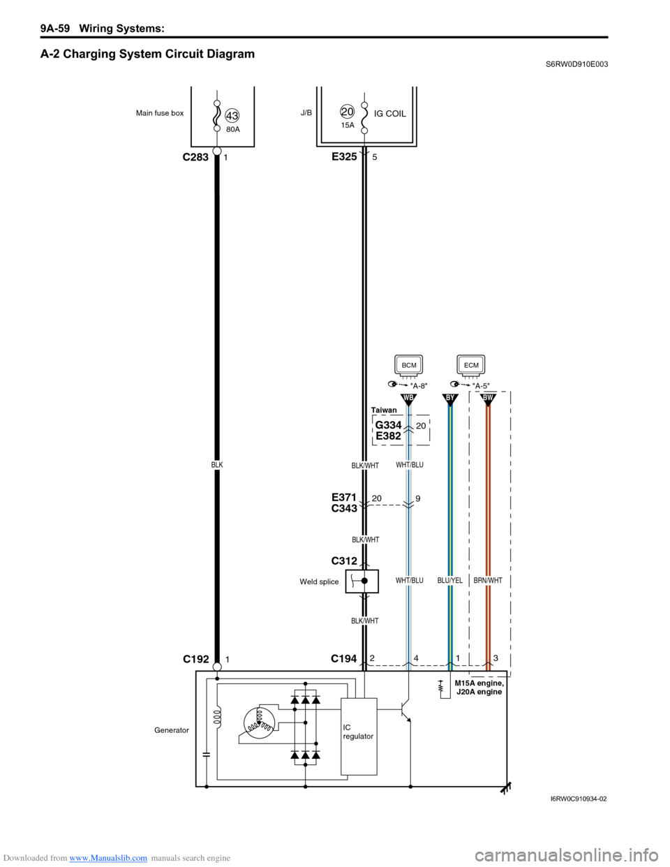
A-2 Charging System Circuit DiagramS6RW0D910E003
20E371
C343
20G334
E382
BLK/WHT
BLK/WHT
BLK/WHT
80A Main fuse box
C192
J/B
1C283
IG COIL4315A
20
GeneratorIC
regulator
1
E3255
C19424
WHT/BLU
WB
BCM
"A-8"
1
BLU/YEL
BY
3
BRN/WHT
BW
ECM
"A-5"
9
WHT/BLUBLK
Weld spliceTaiwan
M15A engine,
J20A engine
C312
I6RW0C910934-02