2006 SUZUKI SX4 Washer
[x] Cancel search: WasherPage 833 of 1556

Downloaded from www.Manualslib.com manuals search engine Manual Transmission/Transaxle: 5B-21
Reassembly
1) Install differential assembly into right case.
2) Join input shaft (5), countershaft (4), low speed gear
shift shaft (2) and high speed gear shift shaft (3)
assemblies all together, then install them into right
case (1) so as not to damage oil seal by input shaft
spline.
NOTE
• Input shaft right bearing on shaft can be
installed into right case (1) by tapping shaft
with plastic hammer.
• Make sure that countershaft is engaged
with final gear while installing.
3) Install 5th & reverse gear shift shaft (1) with 5th &
reverse gear shift guide shaft (2) into right case (5).
Reverse gear shift arm (4) has to be joined with
reverse gear shift lever (3) at the same time.4) Make reverse idler gear (1) with reverse gear shift
lever (2), insert reverse gear shaft (3) and washer (6)
into case (4) through idler gear and then align bolt
hole “a” in shaft with notch “b” in case.
5) Fasten reverse gear shift lever bolts (5) after
applying thread lock cement.
“A”: Thread lock cement 99000–32110 (Thread
Lock Cement Super 1322)
Tightening torque
Reverse gear shift lever bolt (a): 23 N·m (2.3 kgf-
m, 17.0 lb-ft)
NOTE
Check to confirm that reverse gear shift lever
end has clearance “c” to idler gear groove.
Distance between lever end and idler gear shaft
“c”: 0.5 – 1.0 mm (0.02 – 0.04 in.)
I2RH01520080-01
I3RH0A520013-01
I5RW0A520022-02
Page 834 of 1556

Downloaded from www.Manualslib.com manuals search engine 5B-22 Manual Transmission/Transaxle:
6) Clean mating surfaces of both right and left cases,
apply sealant to left case (2) as shown in the figure
by such amount that its section is 1.5 mm (0.059 in.)
in diameter then mate it with right case (1).
“A”: Sealant 99000–31260 (SUZUKI Bond
No.1217G)
7) Tighten case bolts (3) from outside and tighten
another case bolts from clutch housing side to
specified torque.
Tightening torque
Transaxle case bolt (a): 23 N·m (2.3 kgf-m, 17.0
lb-ft)
8) Install reverse shaft bolt (4) to which thread lock
cement has been applied, with aluminum washer
and tighten it to specified torque.
“B”: Sealant 99000–31260 (SUZUKI Bond
No.1217G)
Tightening torque
Reverse shaft bolt (b): 23 N·m (2.3 kgf-m, 17.0
lb-ft)9) Check locating springs (2, 4 and 5) for deterioration
and replace with new ones as necessary.
Locating spring
10) Install steel balls (3) and locating springs (2, 4 and 5)
for respective gear shift shaft and tighten bolts (1) to
which thread lock cement has been applied.
“A”: Thread lock cement 99000–32110 (Thread
Lock Cement Super 1322)
Tightening torque
Gear shift locating bolt (a): 13 N·m (1.3 kgf-m,
9.5 lb-ft)
11) Install new snap ring (1) using special tool.
Special tool
(A): 09900–06107
I5RW0A520023-01
Locating spring free length Standard Service limit
Low speed (2)53.1 mm
(2.091 in.)47.8 mm
(1.881 in.)
High speed (4)45.9 mm
(1.807 in.)41.4 mm
(1.629 in.)
5th & reverse (5)29.9 mm
(1.777 in.)27.0 mm
(1.062 in.)
2. Input shaft
3. Input shaft left bearing
1, (a), “A”
2
3
4
5
I5RW0A520024-02
1 (A)
2
3
I3RH0A520016-01
Page 848 of 1556

Downloaded from www.Manualslib.com manuals search engine 5B-36 Manual Transmission/Transaxle:
Differential ComponentsS6RW0D5206025
Differential Disassembly and ReassemblyS6RW0D5206026
Disassembly
1) Using special tool, remove left bearing (1).
Special tool
(A): 09913–65135
(B): 09913–852302) Using special tool, remove right bearing (1).
Special tool
(A): 09913–65135
(B): 09913–85230
(C): 09940–54950
I5RW0A520043-02
1. Differential pinion washer 6. Differential case : 90 N⋅m (9.0 kgf-m, 65.0 lb-ft)
2. Differential pinion 7. Final gear : Do not reuse.
3. Differential side gear 8. Final gear bolt : Apply transaxle oil.
4. Side gear washer 9. Differential pinion shaft
5. Differential side bearing 10. Differential pinion shaft pin
(B)
(A)
1
I5RW0A520044-01
(A)
1
(B)
(C)
I5RW0A520045-01
Page 849 of 1556

Downloaded from www.Manualslib.com manuals search engine Manual Transmission/Transaxle: 5B-37
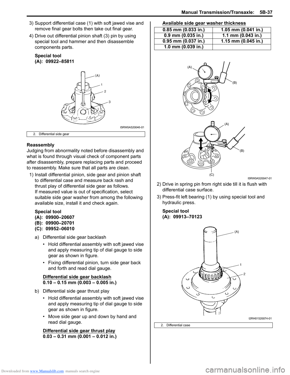
3) Support differential case (1) with soft jawed vise and
remove final gear bolts then take out final gear.
4) Drive out differential pinion shaft (3) pin by using
special tool and hammer and then disassemble
components parts.
Special tool
(A): 09922–85811
Reassembly
Judging from abnormality noted before disassembly and
what is found through visual check of component parts
after disassembly, prepare replacing parts and proceed
to reassembly. Make sure that all parts are clean.
1) Install differential pinion, side gear and pinion shaft
to differential case and measure back rash and
thrust play of differential side gear as follows.
If measured value is out of specification, select
suitable side gear washer from among the following
available size, install it and check again.
Special tool
(A): 09900–20607
(B): 09900–20701
(C): 09952–06010
a) Differential side gear backlash
• Hold differential assembly with soft jawed vise
and apply measuring tip of dial gauge to side
gear as shown in figure.
• Fixing differential pinion, turn side gear back
and forth and read dial gauge.
Differential side gear backlash
0.10 – 0.15 mm (0.003 – 0.005 in.)
b) Differential side gear thrust play
• Hold differential assembly with soft jawed vise
and apply measuring tip of dial gauge to side
gear as shown in figure.
• Move side gear up and down by hand and
read dial gauge.
Differential side gear thrust play
0.03 – 0.31 mm (0.001 – 0.012 in.)Available side gear washer thickness
2) Drive in spring pin from right side till it is flush with
differential case surface.
3) Press-fit left bearing (1) by using special tool and
hydraulic press.
Special tool
(A): 09913–70123
2. Differential side gear
I5RW0A520046-01
0.85 mm (0.033 in.) 1.05 mm (0.041 in.)
0.9 mm (0.035 in.) 1.1 mm (0.043 in.)
0.95 mm (0.037 in.) 1.15 mm (0.045 in.)
1.0 mm (0.039 in.)
2. Differential case
(B)
(B)
(C)
(A)
(A)
I5RW0A520047-01
I2RH01520074-01
Page 915 of 1556

Downloaded from www.Manualslib.com manuals search engine Power Assisted Steering System: 6C-35
Repair Instructions
Steering Gear Case Assembly ComponentsS6RW0D6306001
NOTE
The figure shows left-hand steering vehicle. For right-hand steering vehicle the figure is symmetrical.
8
6
5
9
13
18
17
3
12
7(b)
(b)
(a)
(c)2
1
(e)
(d)
3
(a)
25
6
8
7
9
(b)
(b)
1621
1920
15
1207F
14
4
4
10
11
12(c)
12
(c)
10
11
I6RW0C630010-01
1. Steering gear case 11. Clip 21. O-ring
2. Tie-rod lock washer 12. Steering gear case mounting bolt
: Refer to “Steering Gear Case Assembly Removal and
Installation”. : 75 N⋅m (7.5 kgf-m, 54.5 lb-ft)
3. Tie-rod 13. Steering gear case grommet : 45 N⋅m (4.5 kgf-m, 32.5 lb-ft)
4. Wire 14. Member bracket : 70 N⋅m (7.0 kgf-m, 51.0 lb-ft)
5. Boot 15. Steering rack plunger : Refer to “Steering Rack Plunger Removal and
Installation”.
6. Rack boot clip 16. Steering rack plunger spring : 60 N⋅m (6.0 kgf-m, 43.5 lb-ft)
7. Tie-rod end lock nut 17. Steering rack damper screw
: Apply sealant 99000-31250 to all around thread part of rack
damper screw.: Do not reuse.
8. Tie-rod end 18. Steering rack damper lock nut
9. Tie-rod end nut 19. Washer
10. Boot 20. Spring washer
: Make sure of the direction of installation referring to “Steering
Rack Plunger Removal and Installation”.
Page 919 of 1556

Downloaded from www.Manualslib.com manuals search engine Power Assisted Steering System: 6C-39
7) Unbend bent part of tie-rod lock washer (1).
8) Remove tie-rod (3) from rack (2).
Installation
1) Install tie-rod (1) and new tie-rod lock washer (3) to
rack (2).
2) Hold rack with soft jawed vise and tighten tie-rod to
specified torque.
Tightening torque
Tie-rod (a): 75 N·m (7.5 kgf-m, 54.5 lb-ft)
3) Bend lock washer at 2 places (1) as shown in figure.
4) Apply grease “A” to boot inside as shown in figure.
Position boot properly in grooves of gear case (or
rack side mount) and tie-rod.
After this, check to ensure that boot is free from twist
and dent.
“A”: Grease 99000–25050 (SUZUKI Super
Grease E) 5) Clamp boot with clip and wire. Wire should be new
and should go around the boot twice.
Pull its both ends together by screwdriver or such
and make sure that the wire won’t be crossed. Then
twist the ends 4 – 5 times, the twisted ends should
be bent in the circumferential direction.
NOTE
After clamping, make sure that the boot
installation part is fixed.
If the boot turns easily by hand, tighten with
higher torque to fix it firmly.
6) Install tie-rod end lock nut and tie-rod end to tie-rod.
Position lock nut to marking (1) made in removal.
NOTE
When tie-rod was replaced, measure length
“a” on removed tie-rod and use it on new
replacement tie-rod so as to position lock nut
properly.
7) Install member bracket (1), and then install earth
cable (2) as shown in figure.
Angle “a”
: Within 20°
Tightening torque
Earth cable bolt (a): 4.0 N·m (0.4 kgf-m, 2.8 lb-ft)
3
2
1I5RW0A630021-01
31, (a)
2
I6RW0B630019-01
I4RS0A630035-01
“A”
I7RW01632010-01
IYSQ01630035-01
I3RM0A630052-01
“a”
1
(a)
2
I6RW0C630011-01
Page 920 of 1556

Downloaded from www.Manualslib.com manuals search engine 6C-40 Power Assisted Steering System:
Steering Rack Plunger Removal and InstallationS6RW0D6306009
Removal
1) Loosen lock nut (1) with holding damper screw (2).
2) Remove lock nut (1), rack damper screw (2), rack
plunger spring (3), washer (5), spring washers (6),
O-ring (7) and rack plunger (4).
Installation
1) Install plunger (1), new O-ring (6), washer (4), spring
washers (5) and spring (2) as shown.
NOTE
Do not wipe off grease previously applied to
new plunger.
2) Apply sealant to rack damper screw (3) and tighten
them as follows.
a) Tighten damper screw to 25 N⋅m (2.5 kgf-m, 18.0
lb-ft).
b) Loosen damper screw until 180°.
c) Retighten damper screw to 3.9 N⋅m (0.39 kgf-m,
3.0 lb-ft).
d) After tightening rack damper screw to specified
torque, turn it back by 10° or less.
“A”: Water tight sealant 99000–31250
(SUZUKI Bond No.1207F)
Tightening torque
Rack damper screw (a): Tighten 25 N⋅m (2.5
kgf-m, 18.0 lb-ft) and loosen 180° and then
tighten 3.9 N⋅m (0.39 kgf-m, 3.0 lb-ft) and turn
it back by 10° or less by the specified
procedure.3) Pinion rotation torque should be checked with rack
position centered.
Also, check if rack as a whole moves smoothly.
Special tool
(A): 09944–18220
Tightening torque
Rotation torque of pinion (a): 2.2 N·m (0.22 kgf-
m, 1.5 lb-ft)
4) After adjustment, tighten lock nut to specified torque
with holding damper screw at the position.
Tightening torque
Steering rack damper lock nut: 60 N·m (6.0 kgf-
m, 43.5 lb-ft)Steering Rack Plunger InspectionS6RW0D6306010
NOTE
Do not wipe off grease applied to rack
plunger which is removed.
• Inspect rack plunger (1) for wear or damage.
• Inspect rack plunger spring (2) for deterioration.
If any abnormality is found, replace.
I5RW0A630024-02
I5RW0A630025-03
I3RM0A630055-02
I5RW0A630026-02
Page 1035 of 1556

Downloaded from www.Manualslib.com manuals search engine Seat Belts: 8A-4
Repair Instructions
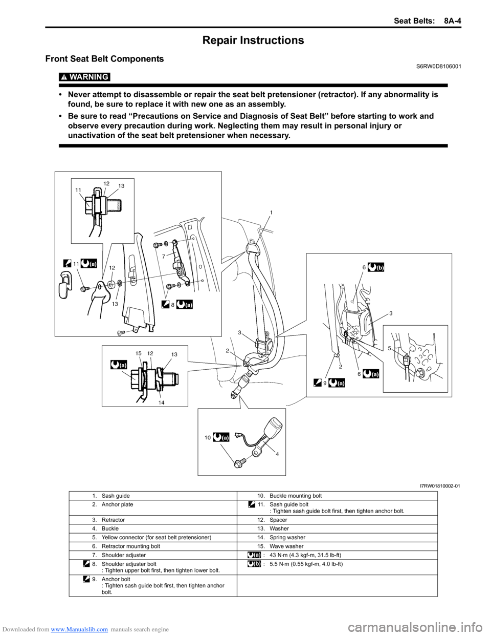
Front Seat Belt ComponentsS6RW0D8106001
WARNING!
• Never attempt to disassemble or repair the seat belt pretensioner (retractor). If any abnormality is
found, be sure to replace it with new one as an assembly.
• Be sure to read “Precautions on Service and Diagnosis of Seat Belt” before starting to work and
observe every precaution during work. Neglecting them may result in personal injury or
unactivation of the seat belt pretensioner when necessary.
I7RW01810002-01
1. Sash guide 10. Buckle mounting bolt
2. Anchor plate 11. Sash guide bolt
: Tighten sash guide bolt first, then tighten anchor bolt.
3. Retractor 12. Spacer
4. Buckle 13. Washer
5. Yellow connector (for seat belt pretensioner) 14. Spring washer
6. Retractor mounting bolt 15. Wave washer
7. Shoulder adjuster : 43 N⋅m (4.3 kgf-m, 31.5 lb-ft)
8. Shoulder adjuster bolt
: Tighten upper bolt first, then tighten lower bolt.: 5.5 N⋅m (0.55 kgf-m, 4.0 lb-ft)
9. Anchor bolt
: Tighten sash guide bolt first, then tighten anchor
bolt.