2006 SUZUKI SX4 Sensors
[x] Cancel search: SensorsPage 1005 of 1556
Downloaded from www.Manualslib.com manuals search engine Air Conditioning System: Automatic Type 7B-65
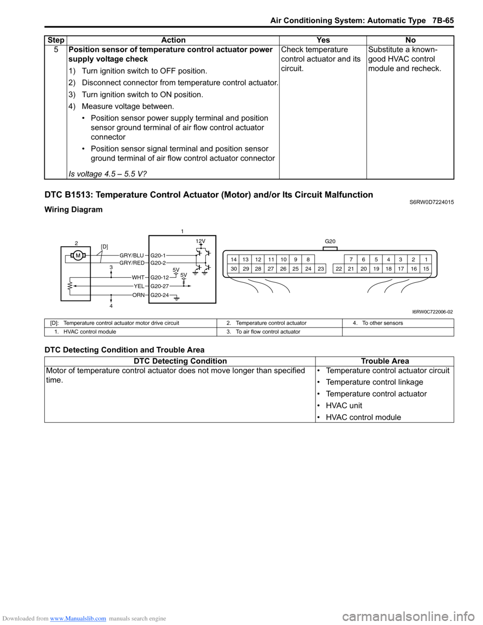
DTC B1513: Temperature Control Actuator (Motor) and/or Its Circuit MalfunctionS6RW0D7224015
Wiring Diagram
DTC Detecting Condition and Trouble Area5Position sensor of temperature control actuator power
supply voltage check
1) Turn ignition switch to OFF position.
2) Disconnect connector from temperature control actuator.
3) Turn ignition switch to ON position.
4) Measure voltage between.
• Position sensor power supply terminal and position
sensor ground terminal of air flow control actuator
connector
• Position sensor signal terminal and position sensor
ground terminal of air flow control actuator connector
Is voltage 4.5 – 5.5 V?Check temperature
control actuator and its
circuit.Substitute a known-
good HVAC control
module and recheck. Step Action Yes No
G20
1 2 3 4 5 6 7 8 9 10 11 12 13 14
15 16 17 18 19 20 21 24 23 22 25 26 27 28 29 30
GRY/BLUGRY/RED
5V5V
12V
ORN
WHT
YEL
G20-12
G20-27
G20-24
G20-1G20-2
2
[D]
3
41
I6RW0C722006-02
[D]: Temperature control actuator motor drive circuit 2. Temperature control actuator 4. To other sensors
1. HVAC control module 3. To air flow control actuator
DTC Detecting Condition Trouble Area
Motor of temperature control actuator does not move longer than specified
time.• Temperature control actuator circuit
• Temperature control linkage
• Temperature control actuator
• HVAC unit
• HVAC control module
Page 1007 of 1556
Downloaded from www.Manualslib.com manuals search engine Air Conditioning System: Automatic Type 7B-67
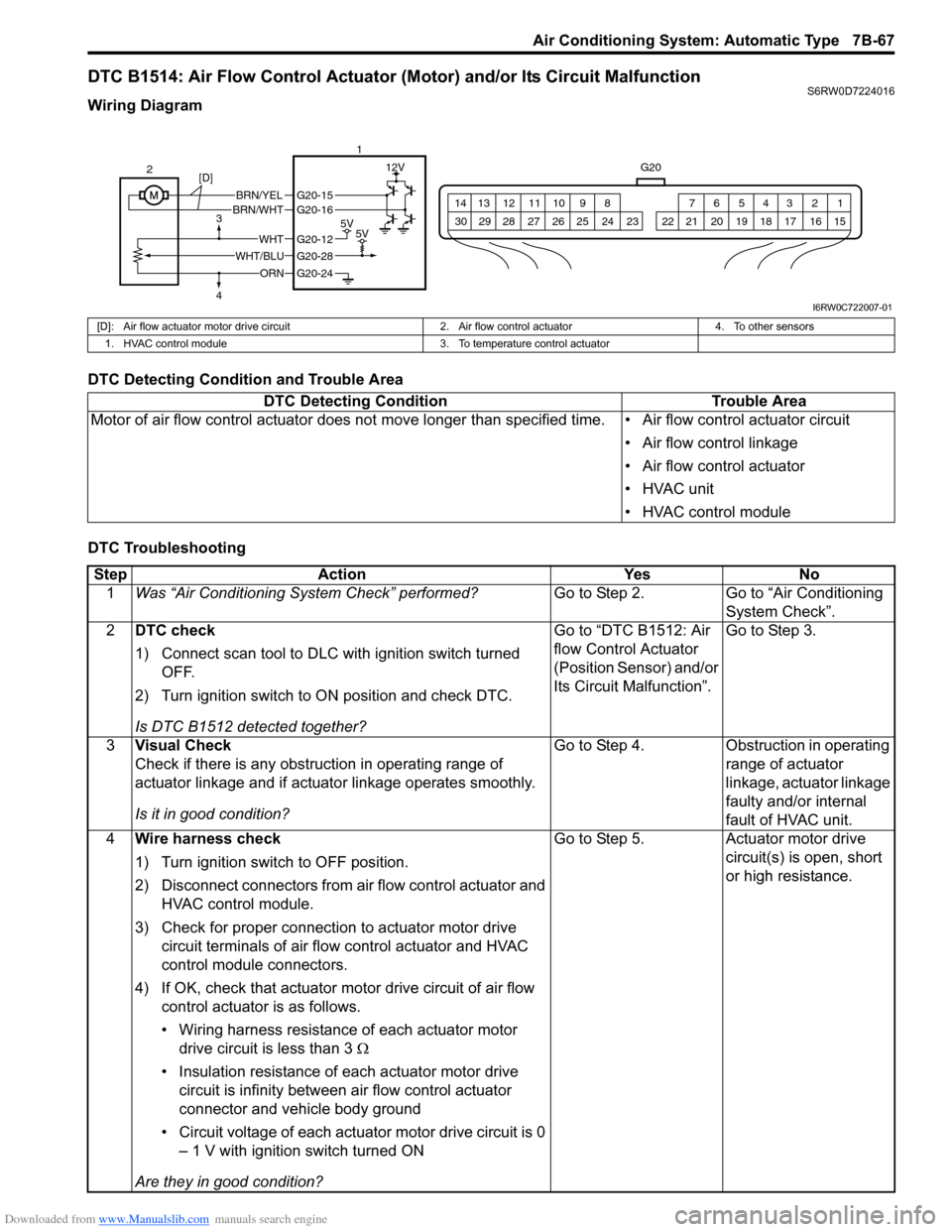
DTC B1514: Air Flow Control Actuator (Motor) and/or Its Circuit MalfunctionS6RW0D7224016
Wiring Diagram
DTC Detecting Condition and Trouble Area
DTC Troubleshooting
G20
1 2 3 4 5 6 7 8 9 10 11 12 13 14
15 16 17 18 19 20 21 24 23 22 25 26 27 28 29 30
BRN/YELBRN/WHT
5V5V
12V
ORN
WHTG20-12
G20-28
G20-24
G20-15G20-16
WHT/BLU 2
3
41
[D]
I6RW0C722007-01
[D]: Air flow actuator motor drive circuit 2. Air flow control actuator 4. To other sensors
1. HVAC control module 3. To temperature control actuator
DTC Detecting Condition Trouble Area
Motor of air flow control actuator does not move longer than specified time. • Air flow control actuator circuit
• Air flow control linkage
• Air flow control actuator
• HVAC unit
• HVAC control module
Step Action Yes No
1Was “Air Conditioning System Check” performed?Go to Step 2. Go to “Air Conditioning
System Check”.
2DTC check
1) Connect scan tool to DLC with ignition switch turned
OFF.
2) Turn ignition switch to ON position and check DTC.
Is DTC B1512 detected together?Go to “DTC B1512: Air
flow Control Actuator
(Position Sensor) and/or
Its Circuit Malfunction”.Go to Step 3.
3Visual Check
Check if there is any obstruction in operating range of
actuator linkage and if actuator linkage operates smoothly.
Is it in good condition?Go to Step 4. Obstruction in operating
range of actuator
linkage, actuator linkage
faulty and/or internal
fault of HVAC unit.
4Wire harness check
1) Turn ignition switch to OFF position.
2) Disconnect connectors from air flow control actuator and
HVAC control module.
3) Check for proper connection to actuator motor drive
circuit terminals of air flow control actuator and HVAC
control module connectors.
4) If OK, check that actuator motor drive circuit of air flow
control actuator is as follows.
• Wiring harness resistance of each actuator motor
drive circuit is less than 3 Ω
• Insulation resistance of each actuator motor drive
circuit is infinity between air flow control actuator
connector and vehicle body ground
• Circuit voltage of each actuator motor drive circuit is 0
– 1 V with ignition switch turned ON
Are they in good condition?Go to Step 5. Actuator motor drive
circuit(s) is open, short
or high resistance.
Page 1017 of 1556
Downloaded from www.Manualslib.com manuals search engine Air Conditioning System: Automatic Type 7B-77
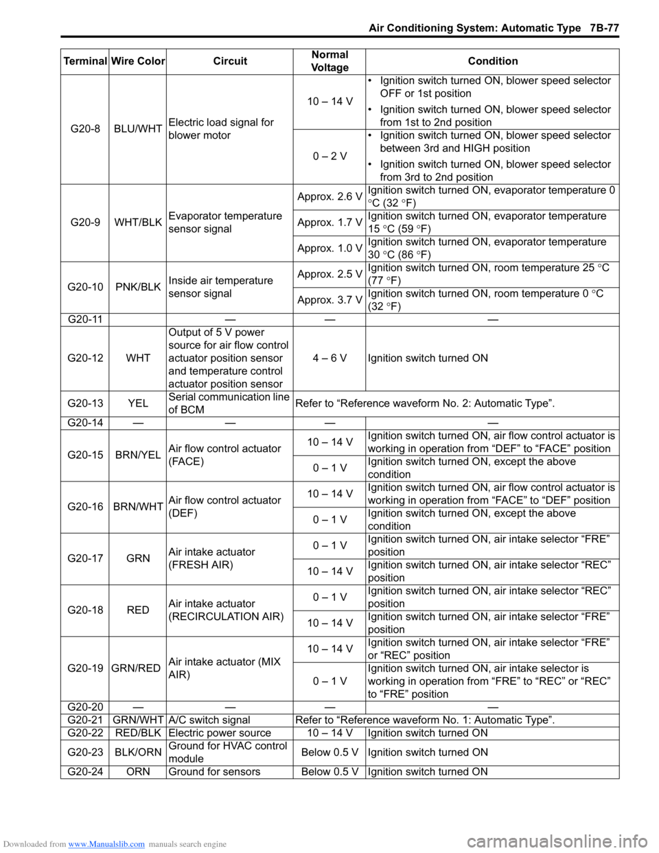
G20-8 BLU/WHTElectric load signal for
blower motor10 – 14 V• Ignition switch turned ON, blower speed selector
OFF or 1st position
• Ignition switch turned ON, blower speed selector
from 1st to 2nd position
0 – 2 V• Ignition switch turned ON, blower speed selector
between 3rd and HIGH position
• Ignition switch turned ON, blower speed selector
from 3rd to 2nd position
G20-9 WHT/BLKEvaporator temperature
sensor signalApprox. 2.6 VIgnition switch turned ON, evaporator temperature 0
°C (32 °F)
Approx. 1.7 VIgnition switch turned ON, evaporator temperature
15 °C (59 °F)
Approx. 1.0 VIgnition switch turned ON, evaporator temperature
30 °C (86 °F)
G20-10 PNK/BLKInside air temperature
sensor signalApprox. 2.5 VIgnition switch turned ON, room temperature 25 °C
(77 °F)
Approx. 3.7 VIgnition switch turned ON, room temperature 0 °C
(32 °F)
G20-11 — — —
G20-12 WHTOutput of 5 V power
source for air flow control
actuator position sensor
and temperature control
actuator position sensor4 – 6 V Ignition switch turned ON
G20-13 YELSerial communication line
of BCMRefer to “Reference waveform No. 2: Automatic Type”.
G20-14 — — — —
G20-15 BRN/YELAir flow control actuator
(FACE)10 – 14 VIgnition switch turned ON, air flow control actuator is
working in operation from “DEF” to “FACE” position
0 – 1 VIgnition switch turned ON, except the above
condition
G20-16 BRN/WHTAir flow control actuator
(DEF)10 – 14 VIgnition switch turned ON, air flow control actuator is
working in operation from “FACE” to “DEF” position
0 – 1 VIgnition switch turned ON, except the above
condition
G20-17 GRNAir intake actuator
(FRESH AIR)0 – 1 VIgnition switch turned ON, air intake selector “FRE”
position
10 – 14 VIgnition switch turned ON, air intake selector “REC”
position
G20-18 REDAir intake actuator
(RECIRCULATION AIR)0 – 1 VIgnition switch turned ON, air intake selector “REC”
position
10 – 14 VIgnition switch turned ON, air intake selector “FRE”
position
G20-19 GRN/REDAir intake actuator (MIX
AIR)10 – 14 VIgnition switch turned ON, air intake selector “FRE”
or “REC” position
0 – 1 VIgnition switch turned ON, air intake selector is
working in operation from “FRE” to “REC” or “REC”
to “FRE” position
G20-20 — — — —
G20-21 GRN/WHT A/C switch signal Refer to “Reference waveform No. 1: Automatic Type”.
G20-22 RED/BLK Electric power source 10 – 14 V Ignition switch turned ON
G20-23 BLK/ORNGround for HVAC control
moduleBelow 0.5 V Ignition switch turned ON
G20-24 ORN Ground for sensors Below 0.5 V Ignition switch turned ON Terminal Wire Color CircuitNormal
Vo l ta g eCondition
Page 1044 of 1556
Downloaded from www.Manualslib.com manuals search engine 8B-5 Air Bag System:
Precautions on Disposal of Air Bag and Seat
Belt Pretensioner
S6RW0D8200003
Do not dispose of the live (undeployed) air bag (inflator)
modules and the live (inactivated) seat belt
pretensioners.
When disposal is necessary, be sure to deploy / activate
the air bag and seat belt pretensioner according to
deployment / activation procedure described in “Air Bag
(Inflator) Module and Seat Belt Pretensioner Disposal”.
WARNING!
Failure to follow proper air bag (inflator)
module and seat belt pretensioner disposal
procedures can result in air bag deployment
and pretensioner activation which could
cause personal injury. Undeployed air bag
(inflator) module and inactivated seat belt
pretensioner must not be disposed of
through normal refuse channels.
The undeployed air bag (inflator) module and
inactivated seat belt pretensioner contain
substances that can cause severe illness or
personal injury if the sealed container is
damaged during disposal.
General Description
Air Bag System ConstructionS6RW0D8201001
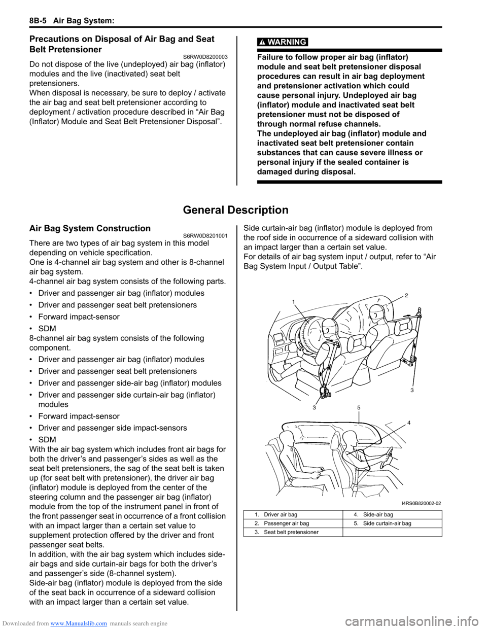
There are two types of air bag system in this model
depending on vehicle specification.
One is 4-channel air bag system and other is 8-channel
air bag system.
4-channel air bag system consists of the following parts.
• Driver and passenger air bag (inflator) modules
• Driver and passenger seat belt pretensioners
• Forward impact-sensor
•SDM
8-channel air bag system consists of the following
component.
• Driver and passenger air bag (inflator) modules
• Driver and passenger seat belt pretensioners
• Driver and passenger side-air bag (inflator) modules
• Driver and passenger side curtain-air bag (inflator)
modules
• Forward impact-sensor
• Driver and passenger side impact-sensors
•SDM
With the air bag system which includes front air bags for
both the driver’s and passenger’s sides as well as the
seat belt pretensioners, the sag of the seat belt is taken
up (for seat belt with pretensioner), the driver air bag
(inflator) module is deployed from the center of the
steering column and the passenger air bag (inflator)
module from the top of the instrument panel in front of
the front passenger seat in occurrence of a front collision
with an impact larger than a certain set value to
supplement protection offered by the driver and front
passenger seat belts.
In addition, with the air bag system which includes side-
air bags and side curtain-air bags for both the driver’s
and passenger’s side (8-channel system).
Side-air bag (inflator) module is deployed from the side
of the seat back in occurrence of a sideward collision
with an impact larger than a certain set value.Side curtain-air bag (inflator) module is deployed from
the roof side in occurrence of a sideward collision with
an impact larger than a certain set value.
For details of air bag system input / output, refer to “Air
Bag System Input / Output Table”.
1. Driver air bag 4. Side-air bag
2. Passenger air bag 5. Side curtain-air bag
3. Seat belt pretensioner
I4RS0B820002-02
Page 1129 of 1556
Downloaded from www.Manualslib.com manuals search engine Air Bag System: 8B-90
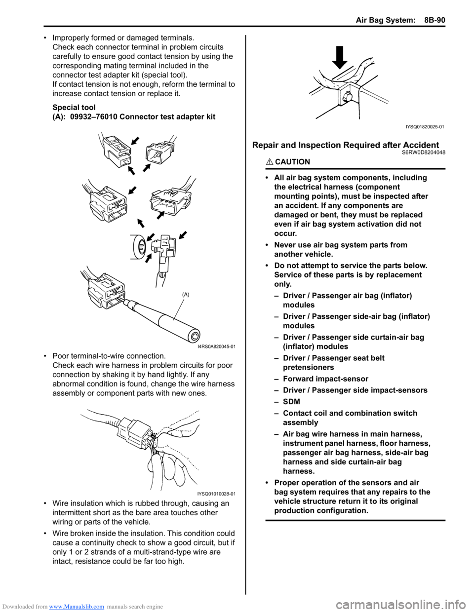
• Improperly formed or damaged terminals.
Check each connector terminal in problem circuits
carefully to ensure good contact tension by using the
corresponding mating terminal included in the
connector test adapter kit (special tool).
If contact tension is not enough, reform the terminal to
increase contact tension or replace it.
Special tool
(A): 09932–76010 Connector test adapter kit
• Poor terminal-to-wire connection.
Check each wire harness in problem circuits for poor
connection by shaking it by hand lightly. If any
abnormal condition is found, change the wire harness
assembly or component parts with new ones.
• Wire insulation which is rubbed through, causing an
intermittent short as the bare area touches other
wiring or parts of the vehicle.
• Wire broken inside the insulation. This condition could
cause a continuity check to show a good circuit, but if
only 1 or 2 strands of a multi-strand-type wire are
intact, resistance could be far too high.
Repair and Inspection Required after AccidentS6RW0D8204048
CAUTION!
• All air bag system components, including
the electrical harness (component
mounting points), must be inspected after
an accident. If any components are
damaged or bent, they must be replaced
even if air bag system activation did not
occur.
• Never use air bag system parts from
another vehicle.
• Do not attempt to service the parts below.
Service of these parts is by replacement
only.
– Driver / Passenger air bag (inflator)
modules
– Driver / Passenger side-air bag (inflator)
modules
– Driver / Passenger side curtain-air bag
(inflator) modules
– Driver / Passenger seat belt
pretensioners
– Forward impact-sensor
– Driver / Passenger side impact-sensors
–SDM
– Contact coil and combination switch
assembly
– Air bag wire harness in main harness,
instrument panel harness, floor harness,
passenger air bag harness, side-air bag
harness and side curtain-air bag
harness.
• Proper operation of the sensors and air
bag system requires that any repairs to the
vehicle structure return it to its original
production configuration.
(A)
I4RS0A820045-01
IYSQ01010028-01
IYSQ01820025-01
Page 1244 of 1556
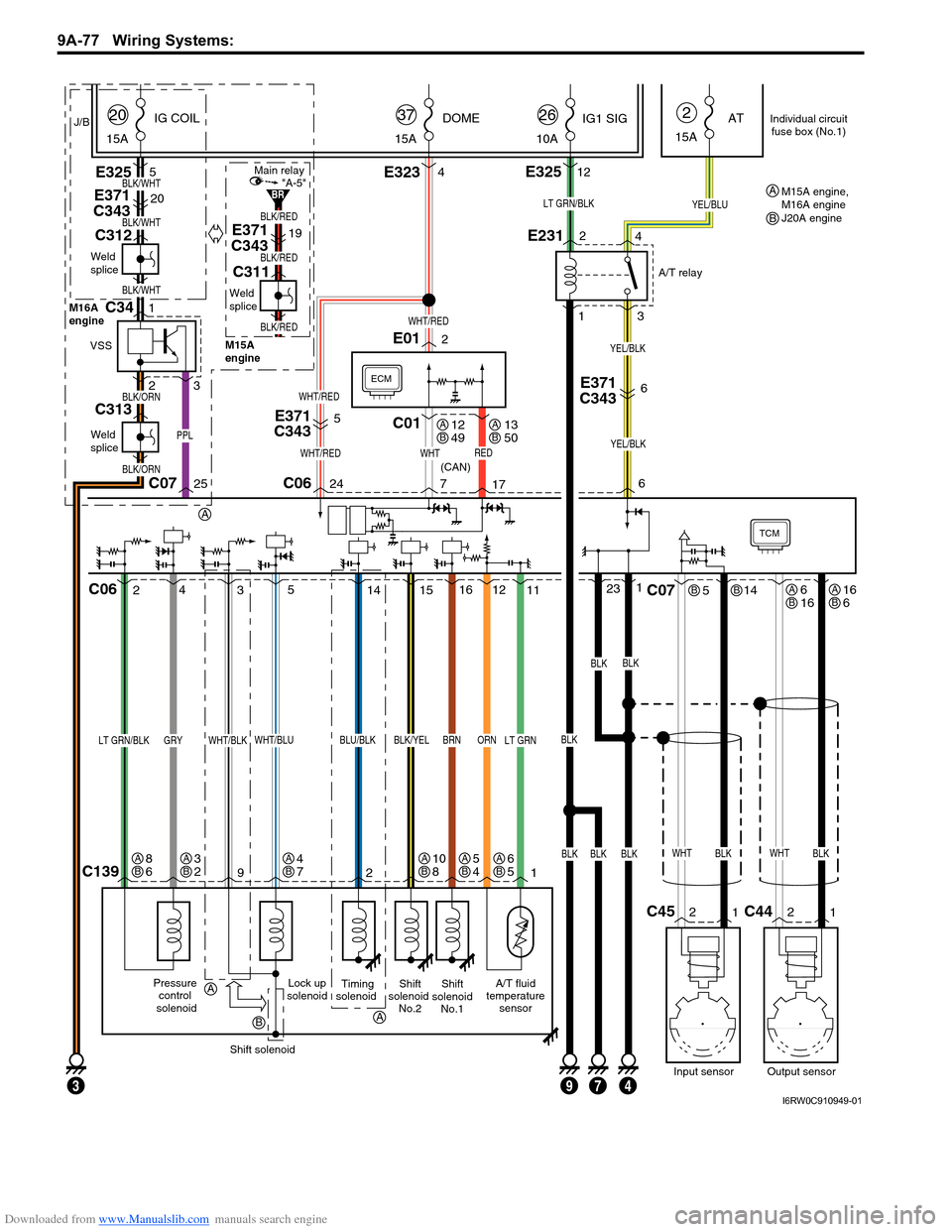
Downloaded from www.Manualslib.com manuals search engine 9A-77 Wiring Systems:
TCM
Lock up
solenoidA/T fluid
temperature
sensorShift
solenoid
No.2Shift
solenoid
No.1
11 12
C1391 2 9
BLK/YELBRNORN
15 4
25
WHT/BLU
Pressure
control
solenoid
LT GRN/BLKGRY
Shift solenoid
LT GRN
ECM
WHTREDWHT/RED
PPL
WHT/RED
BLK/WHT
BLK/RED
BLK/RED
BLK/RED
BLK/WHT
BLK/WHT
5
E371
C343
E371
C34320
E371
C34319
C01
BLKBLKBLK
BLKBLK
E3234E3255
WHT/RED
24 C0625C07717
23116
E012
J/B
15ADOME
37
15AIG COIL
20
15AAT
2
6
3
WHT/BLK
LT GRN/BLK
Timing
solenoid
BLU/BLK
14
WHTBLK
514
2
1C45
Input sensor
C07
WHTBLK
2
1C44
Output sensor
C06
E231
1
3 2
4
YEL/BLU
10AIG1 SIG
26
E32512
BLK
A/T relay
(CAN)
YEL/BLK
7934
E371
C3436
YEL/BLK
Individual circuit
fuse box (No.1)
12
49AB13
50AB
6
16ABBB16
6AB
6
5AB5
4AB4
7AB3
2AB8
6AB10
8AB
A
A
A
B
Weld
splice
M16A
engine
M15A
engine
C312
Weld
splice
C311
BLK/ORN
BLK/ORN
Weld
splice
C313
VSS
1C34
23
"A-5"Main relay
BRM15A engine,
M16A engine
J20A engine A
B
I6RW0C910949-01
Page 1300 of 1556
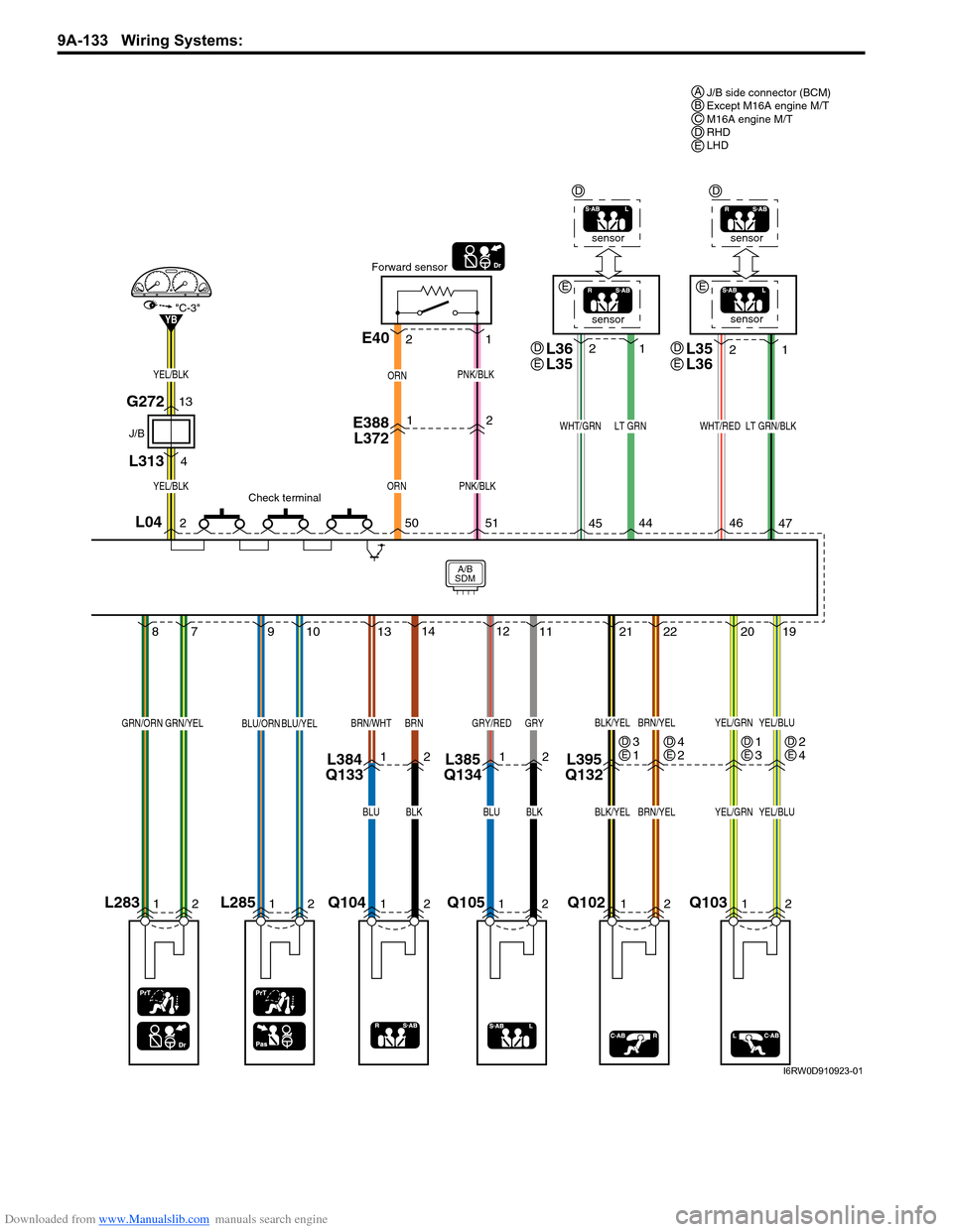
Downloaded from www.Manualslib.com manuals search engine 9A-133 Wiring Systems:
Q102
Q10312
212220
19
BLK/YELBRN/YELYEL/GRNYEL/BLU
BLK/YELBRN/YELYEL/GRNYEL/BLU
12
L395
Q132
1 2
2
454446
47
sensorsensor
LT GRNWHT/GRNWHT/REDLT GRN/BLK
1
2
ORN
YB
E388
L3721
PNK/BLK
E40
Forward sensor
Check terminal
1 2
250
51
ORN
PNK/BLKYEL/BLK
YEL/BLK
"C-3"
J/B
G272
L31313
4
Q105Q10412
A/B
SDM
131412
11
BRN/WHTBRN
12
GRY/REDGRY
BLUBLKBLUBLK
1212L384
Q133L385
Q134
L28512
910
BLU/ORNBLU/YEL
L04
L28312
87
GRN/ORNGRN/YEL
J/B side connector (BCM)
Except M16A engine M/T
M16A engine M/T
RHD
LHD ABCDE
1
3DE4
2DE3
1DE2
4DE
L36
L35D
EE
EL35
L36D
E
sensorsensor
DD
I6RW0D910923-01
Page 1322 of 1556
Downloaded from www.Manualslib.com manuals search engine 9B-3 Lighting Systems:
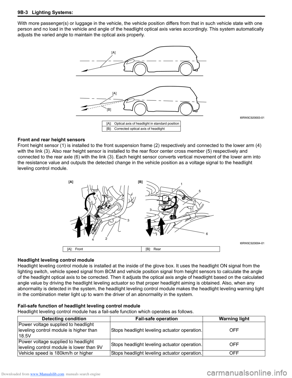
With more passenger(s) or luggage in the vehicle, the vehicle position differs from that in such vehicle state with one
person and no load in the vehicle and angle of the headlight optical axis varies accordingly. This system automatically
adjusts the varied angle to maintain the optical axis properly.
Front and rear height sensors
Front height sensor (1) is installed to the front suspension frame (2) respectively and connected to the lower arm (4)
with the link (3). Also rear height sensor is installed to the rear floor center cross member (5) respectively and
connected to the rear axle (6) with the link (3). Each height sensor converts vertical movement of the lower arm into
the resistance value and outputs the detected change in the vehicle position as a voltage signal to the headlight
leveling control module.
Headlight leveling control module
Headlight leveling control module is installed at the inside of the glove box. It uses the headlight ON signal from the
lighting switch, vehicle speed signal from BCM and vehicle position signal from height sensors to calculate the angle
of the headlight optical axis to be corrected. Then it adjusts the optical axis angle of headlight based on the calculated
angle value by driving the headlight leveling actuator so that proper headlight aiming is obtained. Also, when any
abnormality is detected in the system, the headlight leveling control module makes the headlight leveling warning light
in the combination meter light up to warn the driver of an abnormality in the system.
Fail-safe function of headlight leveling control module
Headlight leveling control module has a fail-safe function which operates as follows.
[A]
[A]
[B]
I6RW0C920003-01
[A]: Optical axis of headlight in standard position
[B]: Corrected optical axis of headlight
1
5
[A] [B]
6
3
1
2
3
4I6RW0C920004-01
[A]: Front [B]: Rear
Detecting condition Fail-safe operation Warning light
Power voltage supplied to headlight
leveling control module is higher than
18.5VStops headlight leveling actuator operation. OFF
Power voltage supplied to headlight
leveling control module is lower than 9VStops headlight leveling actuator operation. OFF
Vehicle speed is 180km/h or higher Stops headlight leveling actuator operation. OFF