2006 SUZUKI SX4 section 1a
[x] Cancel search: section 1aPage 994 of 1556
![SUZUKI SX4 2006 1.G Service Workshop Manual Downloaded from www.Manualslib.com manuals search engine 7B-54 Air Conditioning System: Automatic Type
DTC of A/C System detected by ECM
NOTE
When no DTC is detected, “FRE” [A] and “REC” [B] i SUZUKI SX4 2006 1.G Service Workshop Manual Downloaded from www.Manualslib.com manuals search engine 7B-54 Air Conditioning System: Automatic Type
DTC of A/C System detected by ECM
NOTE
When no DTC is detected, “FRE” [A] and “REC” [B] i](/manual-img/20/7612/w960_7612-993.png)
Downloaded from www.Manualslib.com manuals search engine 7B-54 Air Conditioning System: Automatic Type
DTC of A/C System detected by ECM
NOTE
When no DTC is detected, “FRE” [A] and “REC” [B] indicator lights on HVAC control module flash at
the same time in specific pattern.
Fail-Safe TableS6RW0D7224007
When any of the following malfunctions (DTCs) is detected, fail-safe mode is activated.
However, when HVAC control module detects normal operation of A/C system, fail-safe mode is canceled. DTC No. Detection itemDetecting condition
(DTC will set when detecting)MIL
P0481 Fan 2 Control Circuit
Refer to “Fail-Safe Table in Section 1A”. P0532A/C Refrigerant Pressure
Sensor Circuit Low
P0533A/C Refrigerant Pressure
Sensor Circuit High
H: ON a. About 3 seconds
L: OFF b. About 1 seconds
DTC No. Trouble AreaFail-Safe Operation
When ignition switch is turned ON
after malfunction is already detectedWhen malfunction is detected during
ignition switch is ON
�) B1502Inside air temperature
sensor circuitHVAC control module maintains last
normal value.HVAC control module controls actuators
assuming that inside air temperature is
25 °C (77 °F).
�) B1503A/C evaporator
temperature sensor
circuitHVAC control module assuming that
evaporator temperature is 0 °C (32 °F).• HVAC control module turns off A/C
switch signal.
• HVAC control module controls
actuators assuming that evaporator
temperature is 0 °C (32 °F).
�) B1504 Sunload sensor circuitHVAC control module maintains last
normal value.HVAC control module controls actuators
assuming that amount of sunlight is 0 W/
m
2.
�) B1520Temperature selector
malfunctionHVAC control module maintains last
normal value.HVAC control module controls actuators
assuming that setting of temperature
selector is 25 °C (77 °F) position.
�) B1521Blower speed selector
malfunctionHVAC control module maintains last
normal value.HVAC control module controls actuators
assuming that setting of blower speed
selector is low (1st) position.
�) B1522Air flow selector
malfunctionHVAC control module maintains last
normal value.HVAC control module controls actuators
assuming that setting of air flow selector
is DEF position.
[A]
[A]H
L
H
L [B]
[B]
baaba
baaba
I5RW0A722008-01
Page 1008 of 1556
Downloaded from www.Manualslib.com manuals search engine 7B-68 Air Conditioning System: Automatic Type
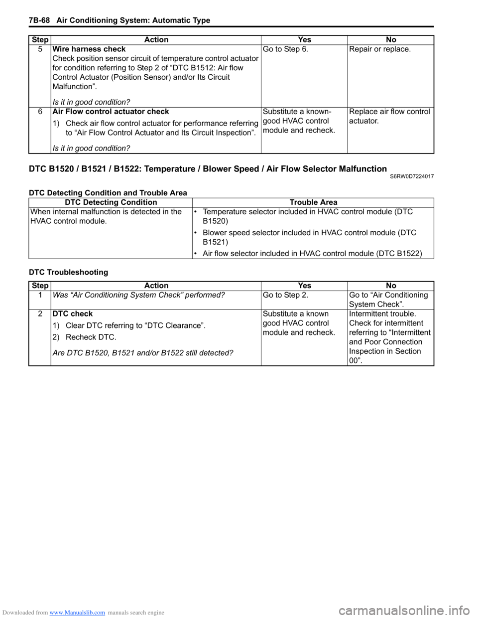
DTC B1520 / B1521 / B1522: Temperature / Blower Speed / Air Flow Selector MalfunctionS6RW0D7224017
DTC Detecting Condition and Trouble Area
DTC Troubleshooting5Wire harness check
Check position sensor circuit of temperature control actuator
for condition referring to Step 2 of “DTC B1512: Air flow
Control Actuator (Position Sensor) and/or Its Circuit
Malfunction”.
Is it in good condition?Go to Step 6. Repair or replace.
6Air Flow control actuator check
1) Check air flow control actuator for performance referring
to “Air Flow Control Actuator and Its Circuit Inspection”.
Is it in good condition?Substitute a known-
good HVAC control
module and recheck.Replace air flow control
actuator. Step Action Yes No
DTC Detecting Condition Trouble Area
When internal malfunction is detected in the
HVAC control module.• Temperature selector included in HVAC control module (DTC
B1520)
• Blower speed selector included in HVAC control module (DTC
B1521)
• Air flow selector included in HVAC control module (DTC B1522)
Step Action Yes No
1Was “Air Conditioning System Check” performed?Go to Step 2. Go to “Air Conditioning
System Check”.
2DTC check
1) Clear DTC referring to “DTC Clearance”.
2) Recheck DTC.
Are DTC B1520, B1521 and/or B1522 still detected?Substitute a known
good HVAC control
module and recheck.Intermittent trouble.
Check for intermittent
referring to “Intermittent
and Poor Connection
Inspection in Section
00”.
Page 1009 of 1556

Downloaded from www.Manualslib.com manuals search engine Air Conditioning System: Automatic Type 7B-69
DTC B1541: Back-Up Power Supply Circuit MalfunctionS6RW0D7224018
Wiring Diagram
DTC Detecting Condition and Trouble Area
NOTE
When checking DTC after connecting battery cable, be sure to turn ignition switch from OFF to ON and
from ON to OFF at least once, or DTC B1541 will be detected.
DTC Troubleshooting
12V5V
WHTG20-7 2
31G201 2 3 4 5 6 7 8 9 10 11 12 13 14
15 16 17 18 19 20 21 24 23 22 25 26 27 28 29 30WHT/RED [B]
I7RW01722011-01
[B]: Back-up power supply circuit 2. Main fuse
1. HVAC control module 3. Circuit fuse
DTC Detecting Condition Trouble Area
• Back-up power supply voltage is lower than specified value continuously.
• When connect battery with vehicle and then, turn ignition switch to ON
position for first time.• Battery voltage supply circuit
• HVAC control module
Step Action Yes No
1Was “Air Conditioning System Check” performed?Go to Step 2. Go to “Air Conditioning
System Check”.
2DTC check
1) Turn ignition switch to ON position for 20 sec. or more.
2) Ignition switch turned OFF and connect scan tool to
DLC.
3) Turn ON ignition switch and check DTC.
Is there DTC B1541?Go to Step 3. Intermittent trouble.
Check for intermittent
referring to “Intermittent
and Poor Connection
Inspection in Section
00”.
3Battery voltage supply circuit check
1) Disconnect connector from HVAC control module with
ignition switch turned OFF.
2) Check for proper connection to back-up power supply
circuit terminal of HVAC control module connector.
3) If OK, measure voltage between back-up power supply
circuit terminal of HVAC control module connector and
vehicle body ground.
Is voltage 10 – 14 V?Substitute a known-
good HVAC control
module and recheck.Back-up power supply
circuit is open or
shorted to ground.
Page 1011 of 1556
Downloaded from www.Manualslib.com manuals search engine Air Conditioning System: Automatic Type 7B-71
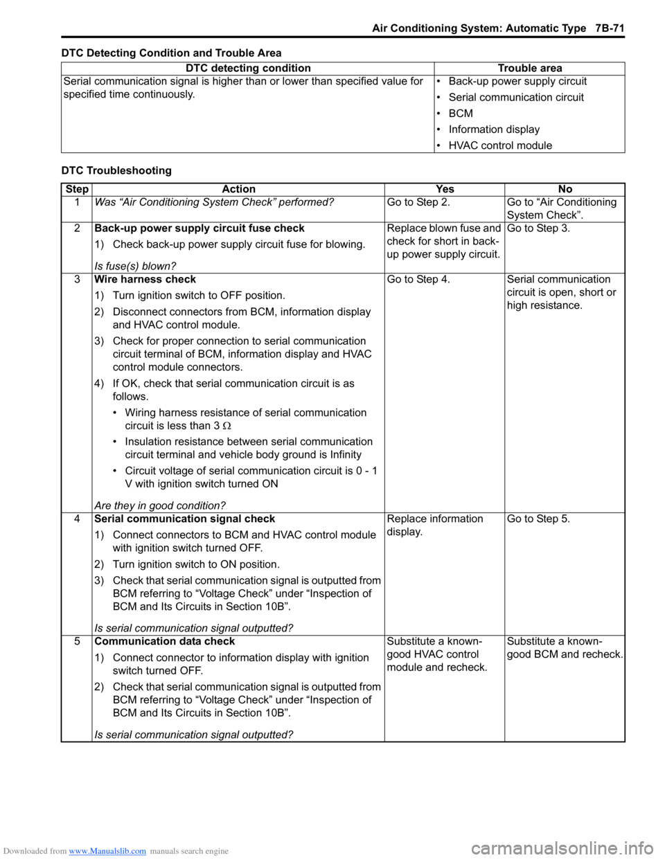
DTC Detecting Condition and Trouble Area
DTC TroubleshootingDTC detecting condition Trouble area
Serial communication signal is higher than or lower than specified value for
specified time continuously.• Back-up power supply circuit
• Serial communication circuit
•BCM
• Information display
• HVAC control module
Step Action Yes No
1Was “Air Conditioning System Check” performed?Go to Step 2. Go to “Air Conditioning
System Check”.
2Back-up power supply circuit fuse check
1) Check back-up power supply circuit fuse for blowing.
Is fuse(s) blown?Replace blown fuse and
check for short in back-
up power supply circuit.Go to Step 3.
3Wire harness check
1) Turn ignition switch to OFF position.
2) Disconnect connectors from BCM, information display
and HVAC control module.
3) Check for proper connection to serial communication
circuit terminal of BCM, information display and HVAC
control module connectors.
4) If OK, check that serial communication circuit is as
follows.
• Wiring harness resistance of serial communication
circuit is less than 3 Ω
• Insulation resistance between serial communication
circuit terminal and vehicle body ground is Infinity
• Circuit voltage of serial communication circuit is 0 - 1
V with ignition switch turned ON
Are they in good condition?Go to Step 4. Serial communication
circuit is open, short or
high resistance.
4Serial communication signal check
1) Connect connectors to BCM and HVAC control module
with ignition switch turned OFF.
2) Turn ignition switch to ON position.
3) Check that serial communication signal is outputted from
BCM referring to “Voltage Check” under “Inspection of
BCM and Its Circuits in Section 10B”.
Is serial communication signal outputted?Replace information
display.Go to Step 5.
5Communication data check
1) Connect connector to information display with ignition
switch turned OFF.
2) Check that serial communication signal is outputted from
BCM referring to “Voltage Check” under “Inspection of
BCM and Its Circuits in Section 10B”.
Is serial communication signal outputted?Substitute a known-
good HVAC control
module and recheck.Substitute a known-
good BCM and recheck.
Page 1012 of 1556
Downloaded from www.Manualslib.com manuals search engine 7B-72 Air Conditioning System: Automatic Type
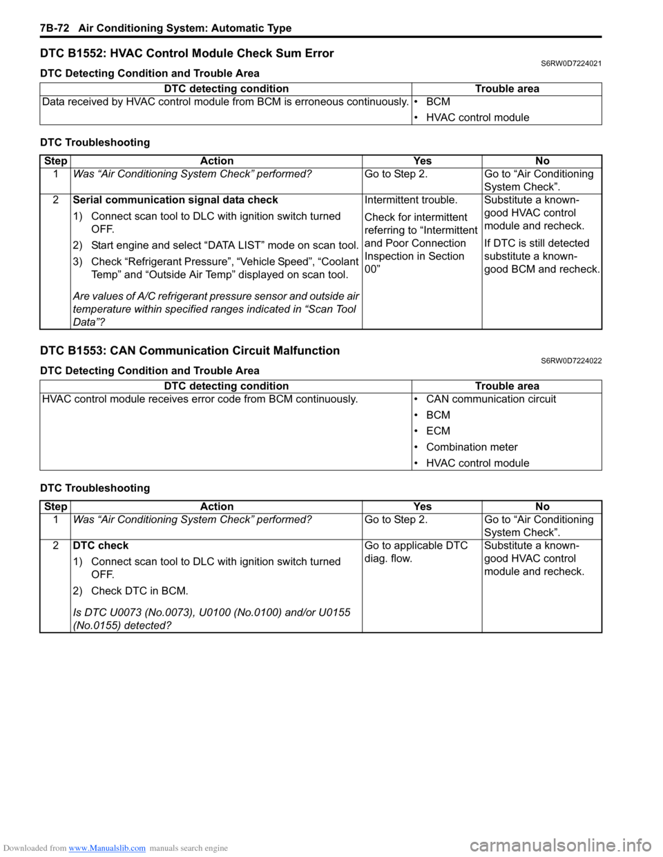
DTC B1552: HVAC Control Module Check Sum ErrorS6RW0D7224021
DTC Detecting Condition and Trouble Area
DTC Troubleshooting
DTC B1553: CAN Communication Circuit MalfunctionS6RW0D7224022
DTC Detecting Condition and Trouble Area
DTC TroubleshootingDTC detecting condition Trouble area
Data received by HVAC control module from BCM is erroneous continuously. • BCM
• HVAC control module
Step Action Yes No
1Was “Air Conditioning System Check” performed?Go to Step 2. Go to “Air Conditioning
System Check”.
2Serial communication signal data check
1) Connect scan tool to DLC with ignition switch turned
OFF.
2) Start engine and select “DATA LIST” mode on scan tool.
3) Check “Refrigerant Pressure”, “Vehicle Speed”, “Coolant
Temp” and “Outside Air Temp” displayed on scan tool.
Are values of A/C refrigerant pressure sensor and outside air
temperature within specified ranges indicated in “Scan Tool
Data”?Intermittent trouble.
Check for intermittent
referring to “Intermittent
and Poor Connection
Inspection in Section
00”Substitute a known-
good HVAC control
module and recheck.
If DTC is still detected
substitute a known-
good BCM and recheck.
DTC detecting condition Trouble area
HVAC control module receives error code from BCM continuously. • CAN communication circuit
•BCM
•ECM
• Combination meter
• HVAC control module
Step Action Yes No
1Was “Air Conditioning System Check” performed?Go to Step 2. Go to “Air Conditioning
System Check”.
2DTC check
1) Connect scan tool to DLC with ignition switch turned
OFF.
2) Check DTC in BCM.
Is DTC U0073 (No.0073), U0100 (No.0100) and/or U0155
(No.0155) detected?Go to applicable DTC
diag. flow.Substitute a known-
good HVAC control
module and recheck.
Page 1015 of 1556
Downloaded from www.Manualslib.com manuals search engine Air Conditioning System: Automatic Type 7B-75
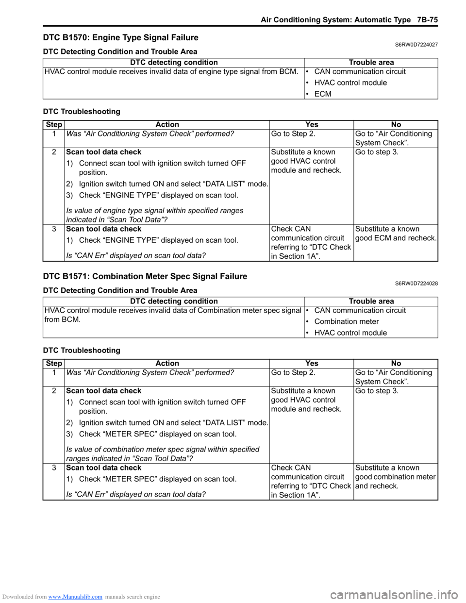
DTC B1570: Engine Type Signal FailureS6RW0D7224027
DTC Detecting Condition and Trouble Area
DTC Troubleshooting
DTC B1571: Combination Meter Spec Signal FailureS6RW0D7224028
DTC Detecting Condition and Trouble Area
DTC TroubleshootingDTC detecting condition Trouble area
HVAC control module receives invalid data of engine type signal from BCM. • CAN communication circuit
• HVAC control module
•ECM
Step Action Yes No
1Was “Air Conditioning System Check” performed?Go to Step 2. Go to “Air Conditioning
System Check”.
2Scan tool data check
1) Connect scan tool with ignition switch turned OFF
position.
2) Ignition switch turned ON and select “DATA LIST” mode.
3) Check “ENGINE TYPE” displayed on scan tool.
Is value of engine type signal within specified ranges
indicated in “Scan Tool Data”?Substitute a known
good HVAC control
module and recheck.Go to step 3.
3Scan tool data check
1) Check “ENGINE TYPE” displayed on scan tool.
Is “CAN Err” displayed on scan tool data?Check CAN
communication circuit
referring to “DTC Check
in Section 1A”.Substitute a known
good ECM and recheck.
DTC detecting condition Trouble area
HVAC control module receives invalid data of Combination meter spec signal
from BCM.• CAN communication circuit
• Combination meter
• HVAC control module
Step Action Yes No
1Was “Air Conditioning System Check” performed?Go to Step 2. Go to “Air Conditioning
System Check”.
2Scan tool data check
1) Connect scan tool with ignition switch turned OFF
position.
2) Ignition switch turned ON and select “DATA LIST” mode.
3) Check “METER SPEC” displayed on scan tool.
Is value of combination meter spec signal within specified
ranges indicated in “Scan Tool Data”?Substitute a known
good HVAC control
module and recheck.Go to step 3.
3Scan tool data check
1) Check “METER SPEC” displayed on scan tool.
Is “CAN Err” displayed on scan tool data?Check CAN
communication circuit
referring to “DTC Check
in Section 1A”.Substitute a known
good combination meter
and recheck.
Page 1019 of 1556
Downloaded from www.Manualslib.com manuals search engine Air Conditioning System: Automatic Type 7B-79
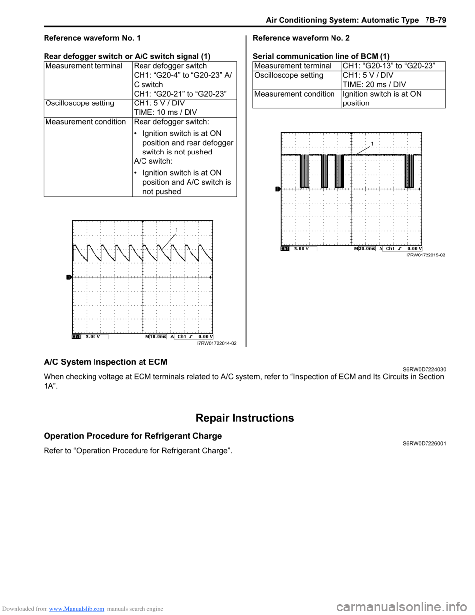
Reference waveform No. 1
Rear defogger switch or A/C switch signal (1)Reference waveform No. 2
Serial communication line of BCM (1)
A/C System Inspection at ECMS6RW0D7224030
When checking voltage at ECM terminals related to A/C system, refer to “Inspection of ECM and Its Circuits in Section
1A”.
Repair Instructions
Operation Procedure for Refrigerant ChargeS6RW0D7226001
Refer to “Operation Procedure for Refrigerant Charge”.Measurement terminal Rear defogger switch
CH1: “G20-4” to “G20-23” A/
C switch
CH1: “G20-21” to “G20-23”
Oscilloscope setting CH1: 5 V / DIV
TIME: 10 ms / DIV
Measurement condition Rear defogger switch:
• Ignition switch is at ON
position and rear defogger
switch is not pushed
A/C switch:
• Ignition switch is at ON
position and A/C switch is
not pushed
I7RW01722014-02
Measurement terminal CH1: “G20-13” to “G20-23”
Oscilloscope setting CH1: 5 V / DIV
TIME: 20 ms / DIV
Measurement condition Ignition switch is at ON
position
I7RW01722015-02
Page 1024 of 1556
Downloaded from www.Manualslib.com manuals search engine 7B-84 Air Conditioning System: Automatic Type
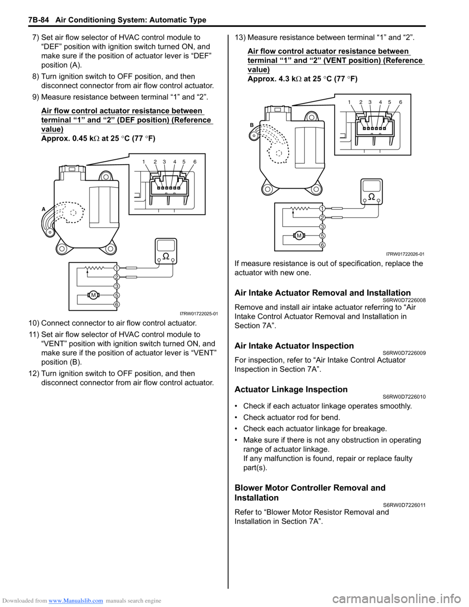
7) Set air flow selector of HVAC control module to
“DEF” position with ignition switch turned ON, and
make sure if the position of actuator lever is “DEF”
position (A).
8) Turn ignition switch to OFF position, and then
disconnect connector from air flow control actuator.
9) Measure resistance between terminal “1” and “2”.
Air flow control actuator resistance between
terminal “1” and “2” (DEF position) (Reference
value)
Approx. 0.45 kΩ at 25 °C (77 °F)
10) Connect connector to air flow control actuator.
11) Set air flow selector of HVAC control module to
“VENT” position with ignition switch turned ON, and
make sure if the position of actuator lever is “VENT”
position (B).
12) Turn ignition switch to OFF position, and then
disconnect connector from air flow control actuator.13) Measure resistance between terminal “1” and “2”.
Air flow control actuator resistance between
terminal “1” and “2” (VENT position) (Reference
value)
Approx. 4.3 kΩ at 25 °C (77 °F)
If measure resistance is out of specification, replace the
actuator with new one.
Air Intake Actuator Removal and InstallationS6RW0D7226008
Remove and install air intake actuator referring to “Air
Intake Control Actuator Removal and Installation in
Section 7A”.
Air Intake Actuator InspectionS6RW0D7226009
For inspection, refer to “Air Intake Control Actuator
Inspection in Section 7A”.
Actuator Linkage InspectionS6RW0D7226010
• Check if each actuator linkage operates smoothly.
• Check actuator rod for bend.
• Check each actuator linkage for breakage.
• Make sure if there is not any obstruction in operating
range of actuator linkage.
If any malfunction is found, repair or replace faulty
part(s).
Blower Motor Controller Removal and
Installation
S6RW0D7226011
Refer to “Blower Motor Resistor Removal and
Installation in Section 7A”.
123456
6
M5
3
2
1 A
I7RW01722025-01
123456
6
M5
3
2
1 B
I7RW01722026-01