2006 SUZUKI SX4 lock
[x] Cancel search: lockPage 1426 of 1556
Downloaded from www.Manualslib.com manuals search engine 9F-15 Security and Locks:
Keyless Entry Receiver and Its Circuit Inspection (If Equipped)S6RW0D9606017
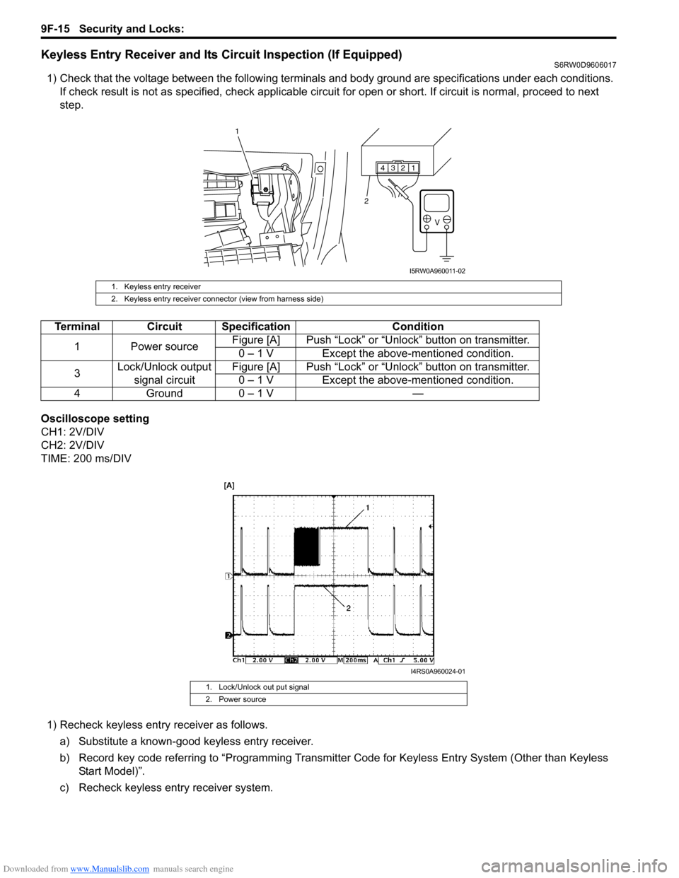
1) Check that the voltage between the following terminals and body ground are specifications under each conditions.
If check result is not as specified, check applicable circuit for open or short. If circuit is normal, proceed to next
step.
Oscilloscope setting
CH1: 2V/DIV
CH2: 2V/DIV
TIME: 200 ms/DIV
1) Recheck keyless entry receiver as follows.
a) Substitute a known-good keyless entry receiver.
b) Record key code referring to “Programming Transmitter Code for Keyless Entry System (Other than Keyless
Start Model)”.
c) Recheck keyless entry receiver system.
1. Keyless entry receiver
2. Keyless entry receiver connector (view from harness side)
Terminal Circuit Specification Condition
1 Power sourceFigure [A] Push “Lock” or “Unlock” button on transmitter.
0 – 1 V Except the above-mentioned condition.
3Lock/Unlock output
signal circuitFigure [A] Push “Lock” or “Unlock” button on transmitter.
0 – 1 V Except the above-mentioned condition.
4 Ground 0 – 1 V —
1. Lock/Unlock out put signal
2. Power source
1 2 3 4
V
2
1
I5RW0A960011-02
I4RS0A960024-01
Page 1427 of 1556
Downloaded from www.Manualslib.com manuals search engine Security and Locks: 9F-16
Specifications
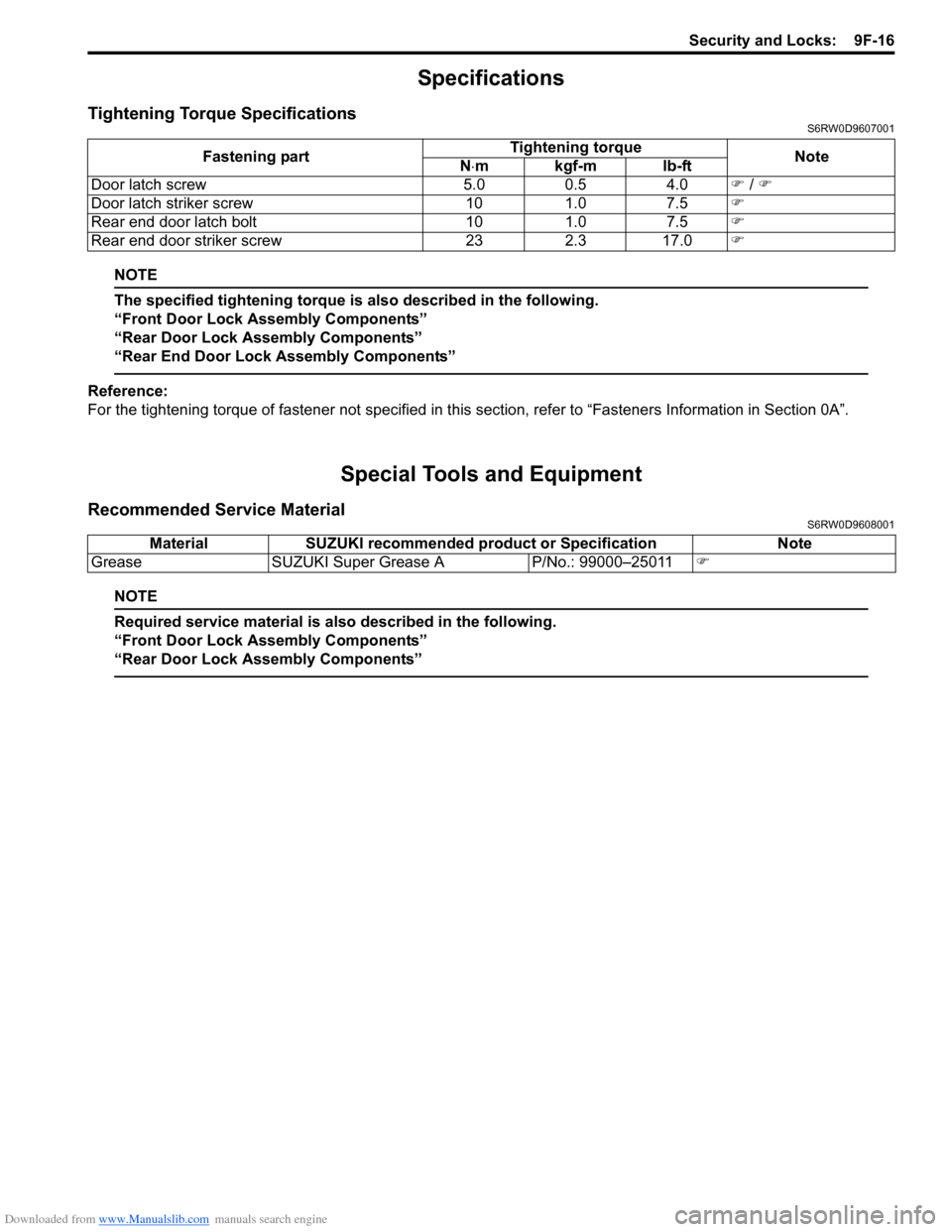
Tightening Torque SpecificationsS6RW0D9607001
NOTE
The specified tightening torque is also described in the following.
“Front Door Lock Assembly Components”
“Rear Door Lock Assembly Components”
“Rear End Door Lock Assembly Components”
Reference:
For the tightening torque of fastener not specified in this section, refer to “Fasteners Information in Section 0A”.
Special Tools and Equipment
Recommended Service MaterialS6RW0D9608001
NOTE
Required service material is also described in the following.
“Front Door Lock Assembly Components”
“Rear Door Lock Assembly Components”
Fastening partTightening torque
Note
N⋅mkgf-mlb-ft
Door latch screw 5.0 0.5 4.0�) / �)
Door latch striker screw 10 1.0 7.5�)
Rear end door latch bolt 10 1.0 7.5�)
Rear end door striker screw 23 2.3 17.0�)
Material SUZUKI recommended product or Specification Note
Grease SUZUKI Super Grease A P/No.: 99000–25011�)
Page 1431 of 1556
Downloaded from www.Manualslib.com manuals search engine Seats: 9G-4
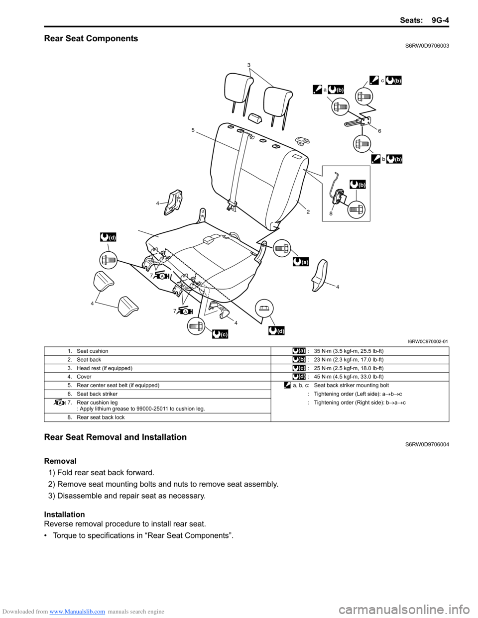
Rear Seat ComponentsS6RW0D9706003
Rear Seat Removal and InstallationS6RW0D9706004
Removal
1) Fold rear seat back forward.
2) Remove seat mounting bolts and nuts to remove seat assembly.
3) Disassemble and repair seat as necessary.
Installation
Reverse removal procedure to install rear seat.
• Torque to specifications in “Rear Seat Components”.
3
5
4
4
4
7
4
2
6
b
c
a
(d)
(a)
(d)
(b)
(b)
(b)
(c)
A
7A
(b)
8
I6RW0C970002-01
1. Seat cushion:35 N⋅m (3.5 kgf-m, 25.5 lb-ft)
2. Seat back:23 N⋅m (2.3 kgf-m, 17.0 lb-ft)
3. Head rest (if equipped):25 N⋅m (2.5 kgf-m, 18.0 lb-ft)
4. Cover:45 N⋅m (4.5 kgf-m, 33.0 lb-ft)
5. Rear center seat belt (if equipped) a, b, c: Seat back striker mounting bolt
6. Seat back striker: Tightening order (Left side): a→b→c
7. Rear cushion leg
: Apply lithium grease to 99000-25011 to cushion leg.: Tightening order (Right side): b→a→c
8. Rear seat back lock
Page 1437 of 1556
Downloaded from www.Manualslib.com manuals search engine Hood / Fenders / Doors: 9J-1
Body, Cab and Accessories
Hood / Fenders / Doors
Repair Instructions
Hood Removal and InstallationS6RW0D9A06001
Removal
CAUTION!
Place cloth to prevent body from any
damage.
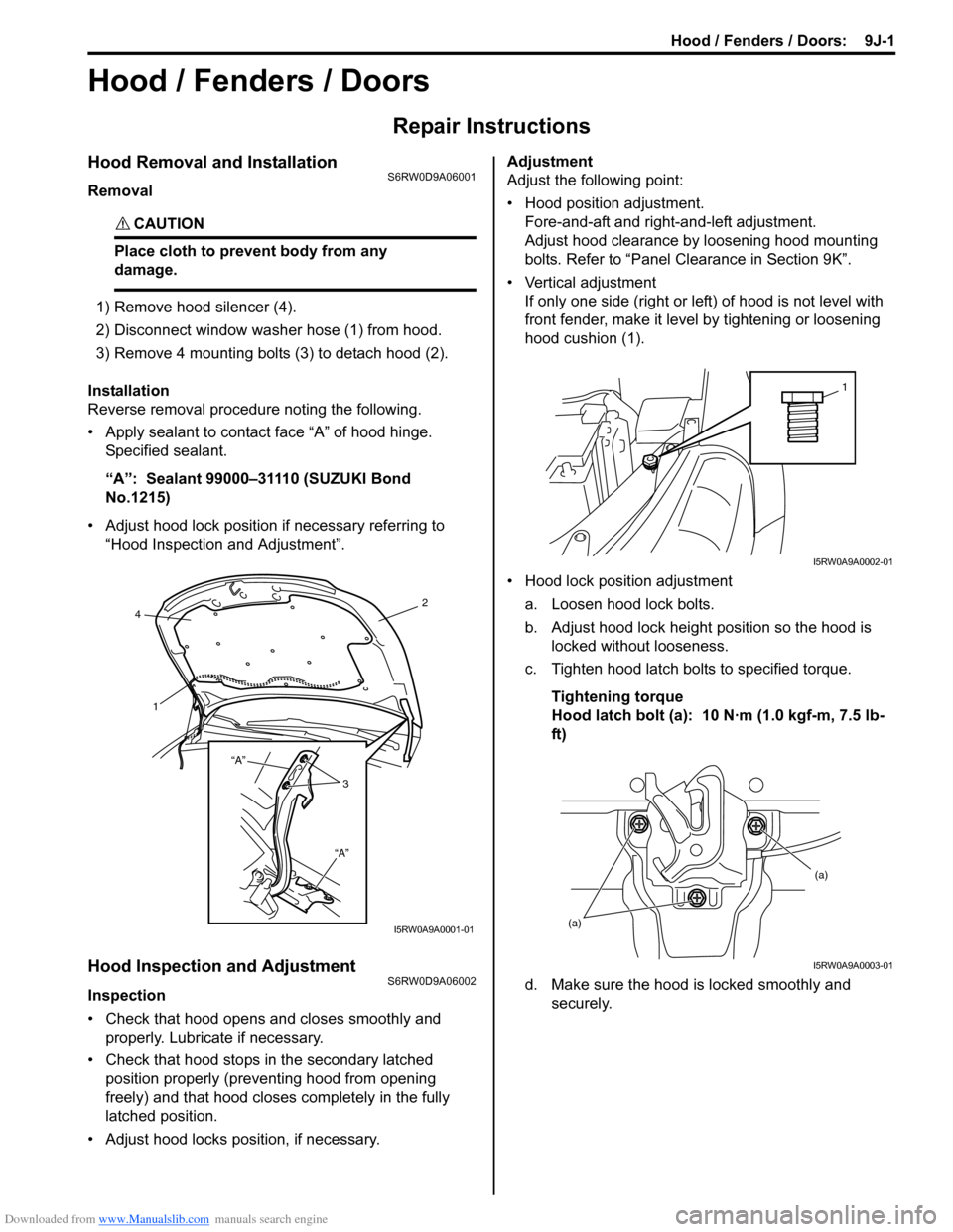
1) Remove hood silencer (4).
2) Disconnect window washer hose (1) from hood.
3) Remove 4 mounting bolts (3) to detach hood (2).
Installation
Reverse removal procedure noting the following.
• Apply sealant to contact face “A” of hood hinge.
Specified sealant.
“A”: Sealant 99000–31110 (SUZUKI Bond
No.1215)
• Adjust hood lock position if necessary referring to
“Hood Inspection and Adjustment”.
Hood Inspection and AdjustmentS6RW0D9A06002
Inspection
• Check that hood opens and closes smoothly and
properly. Lubricate if necessary.
• Check that hood stops in the secondary latched
position properly (preventing hood from opening
freely) and that hood closes completely in the fully
latched position.
• Adjust hood locks position, if necessary.Adjustment
Adjust the following point:
• Hood position adjustment.
Fore-and-aft and right-and-left adjustment.
Adjust hood clearance by loosening hood mounting
bolts. Refer to “Panel Clearance in Section 9K”.
• Vertical adjustment
If only one side (right or left) of hood is not level with
front fender, make it level by tightening or loosening
hood cushion (1).
• Hood lock position adjustment
a. Loosen hood lock bolts.
b. Adjust hood lock height position so the hood is
locked without looseness.
c. Tighten hood latch bolts to specified torque.
Tightening torque
Hood latch bolt (a): 10 N·m (1.0 kgf-m, 7.5 lb-
ft)
d. Make sure the hood is locked smoothly and
securely.
2
4
1
3 “A”
“A”
I5RW0A9A0001-01
1
I5RW0A9A0002-01
(a)(a)
I5RW0A9A0003-01
Page 1440 of 1556
Downloaded from www.Manualslib.com manuals search engine 9J-4 Hood / Fenders / Doors:
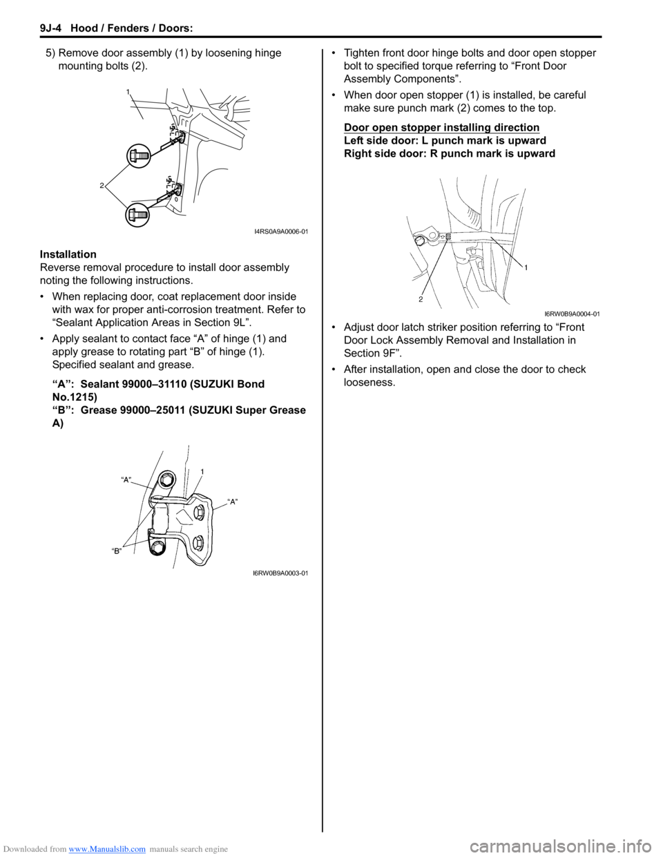
5) Remove door assembly (1) by loosening hinge
mounting bolts (2).
Installation
Reverse removal procedure to install door assembly
noting the following instructions.
• When replacing door, coat replacement door inside
with wax for proper anti-corrosion treatment. Refer to
“Sealant Application Areas in Section 9L”.
• Apply sealant to contact face “A” of hinge (1) and
apply grease to rotating part “B” of hinge (1).
Specified sealant and grease.
“A”: Sealant 99000–31110 (SUZUKI Bond
No.1215)
“B”: Grease 99000–25011 (SUZUKI Super Grease
A) • Tighten front door hinge bolts and door open stopper
bolt to specified torque referring to “Front Door
Assembly Components”.
• When door open stopper (1) is installed, be careful
make sure punch mark (2) comes to the top.
Door open stopper installing direction
Left side door: L punch mark is upward
Right side door: R punch mark is upward
• Adjust door latch striker position referring to “Front
Door Lock Assembly Removal and Installation in
Section 9F”.
• After installation, open and close the door to check
looseness.
1
2
I4RS0A9A0006-01
I6RW0B9A0003-01
I6RW0B9A0004-01
Page 1443 of 1556
Downloaded from www.Manualslib.com manuals search engine Hood / Fenders / Doors: 9J-7
WARNING!
Handling of rear end door balancer (damper)
• Handle balancer carefully. Do not scar or
scratch exposed surface of its piston rod,
and never allow any paint or oil to stick to
its surface.
• Do not turn piston rod with balancer fully
extended.
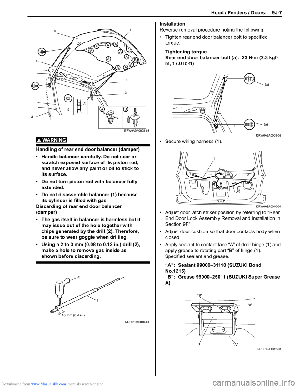
• Do not disassemble balancer (1) because
its cylinder is filled with gas.
Discarding of rear end door balancer
(damper)
• The gas itself in balancer is harmless but it
may issue out of the hole together with
chips generated by the drill (2). Therefore,
be sure to wear goggle when drilling.
• Using a 2 to 3 mm (0.08 to 0.12 in.) drill (2),
make a hole to remove gas inside as
shown before discarding.
Installation
Reverse removal procedure noting the following.
• Tighten rear end door balancer bolt to specified
torque.
Tightening torque
Rear end door balancer bolt (a): 23 N·m (2.3 kgf-
m, 17.0 lb-ft)
• Secure wiring harness (1).
• Adjust door latch striker position by referring to “Rear
End Door Lock Assembly Removal and Installation in
Section 9F”.
• Adjust door cushion so that door contacts body when
closed.
• Apply sealant to contact face “A” of door hinge (1) and
apply grease to rotating part “B” of hinge (1).
Specified sealant and grease.
“A”: Sealant 99000–31110 (SUZUKI Bond
No.1215)
“B”: Grease 99000–25011 (SUZUKI Super Grease
A)
AB
A
A
A
A
AAA
AAA
B
3
5
461
4
2
2
I5RW0A9A0008-03
I2RH019A0010-01
(a)
(a)
I5RW0A9A0009-02
1
I5RW0A9A0010-01
I2RH019A1012-01
Page 1471 of 1556
Downloaded from www.Manualslib.com manuals search engine Table of Contents 10- i
10
Section 10
CONTENTS
Control Systems
Precautions ............................................... 10-1
Precautions........................................................... 10-1
Precautions for Control Systems......................... 10-1
Body Electrical Control System ........... 10B-1
Precautions......................................................... 10B-1
Precautions in Diagnosing Trouble ................... 10B-1
General Description ........................................... 10B-1
BCM General Description ................................. 10B-1
CAN Communication System Description......... 10B-1
Theft Deterrent Light ......................................... 10B-2
Security Alarm Description (If Equipped) .......... 10B-2
Schematic and Routing Diagram ...................... 10B-3
Body Electrical Control System Wiring Circuit
Diagram .......................................................... 10B-3
Connector Layout Diagram of BCM and
Junction Block ................................................. 10B-6
Component Location ......................................... 10B-7
BCM and Related System Component
Location .......................................................... 10B-7
Diagnostic Information and Procedures .......... 10B-8
BCM Self-Diagnosis Function ........................... 10B-8
Body Electrical Control System Check.............. 10B-9
Scan Tool Data ............................................... 10B-11
DTC Table ....................................................... 10B-13
DTC Check ..................................................... 10B-14
DTC Clearance ............................................... 10B-15
BCM Power Circuit and Ground Circuit Check 10B-16
DTC B1133 (DTC No. 1133): Battery Voltage
Too High ....................................................... 10B-17
DTC B1141 / DTC B1142 (No. 1141 / No.
1142) Outside Air Temperature (Ambient
Temp.) Sensor Circuit Malfunction ................ 10B-18
DTC B1150 (No. 1150): Air Bag
Communication Circuit Malfunction .............. 10B-19
DTC B1157 (No. 1157) Air Bag Deployment
Signal Input ................................................... 10B-20
DTC B1170 (No. 1170): EEPROM Access
Error .............................................................. 10B-20
DTC U0073 (No. 0073): Control Module
Communication Bus Off ................................ 10B-20
DTC U0100 (No. 0100): Lost Communication
with ECM....................................................... 10B-20DTC U0101 (No. 0101): Lost Communication
with TCM ....................................................... 10B-20
DTC U0155 (No. 0155): Lost Communication
with Instrument Panel Cluster (IPC) Control
Module .......................................................... 10B-20
DTC U1144 (No. 1144): Lost Communication
with Keyless Start Control Module ................ 10B-20
Inspection of BCM and Its Circuits .................. 10B-21
Repair Instructions ..........................................10B-28
BCM (Included in Junction Block) Removal
and Installation .............................................. 10B-28
Security Alarm Mode Selection Procedure (If
Equipped) ...................................................... 10B-29
Outside Air Temperature Sensor Removal
and Installation .............................................. 10B-29
Outside Air Temperature Sensor Inspection ... 10B-29
Special Tools and Equipment .........................10B-29
Special Tool .................................................... 10B-29
Immobilizer Control System ................. 10C-1
Precautions.........................................................10C-1
Precautions in Diagnosing Troubles .................10C-1
Precaution in Replacing ECM ...........................10C-1
Precaution in Replacing Ignition Key ................10C-1
Precautions in Handling Immobilizer Control
System ............................................................10C-1
General Description ...........................................10C-2
Immobilizer Control System Introduction ..........10C-2
On-Board Diagnostic System Description
(Self-diagnosis Function)................................10C-2
Schematic and Routing Diagram ......................10C-3
Immobilizer Control System Wiring Circuit
Diagram...........................................................10C-3
Component Location .........................................10C-5
Immobilizer Control System Components
Location...........................................................10C-5
Diagnostic Information and Procedures ..........10C-5
Immobilizer Control System Check ...................10C-5
DTC Check........................................................10C-6
DTC Clearance .................................................10C-6
DTC Table .........................................................10C-7
Scan Tool Data .................................................10C-8
Immobilizer Indicator Light Does Not Come
ON with Ignition Switch ON and Engine Stop ..10C-9
Page 1472 of 1556
Downloaded from www.Manualslib.com manuals search engine 10-ii Table of Contents
Immobilizer Indicator Light Remains ON after
Engine Start ..................................................10C-10
DTC P1614: Transponder Response Error .....10C-10
DTC P1615: Steering Lock Unit
Communication Error ....................................10C-11
DTC P1616: Unregistered Keyless Start
Control Module ..............................................10C-12
DTC P1618: Keyless Start Control Module
CAN Communication Error............................10C-13
DTC P1621: Immobilizer Communication
Line Error ......................................................10C-13
DTC P1622: EEPROM Reading / Writing
Error ..............................................................10C-14
DTC P1623: Unregistered Transponder .........10C-14
DTC P1625: Immobilizer Antenna Error..........10C-15
DTC P1636: Immobilizer Information
Registration Failure .......................................10C-15
DTC P1638: Immobilizer Information
Mismatched ...................................................10C-16
Inspection of ICM and Its Circuit .....................10C-17
Repair Instructions ..........................................10C-19
ICM Removal and Installation .........................10C-19
Registration of the Ignition Key .......................10C-19
Procedure after ECM Replacement ................10C-19
Special Tools and Equipment .........................10C-20
Special Tool ....................................................10C-20
Keyless Start System .............................10E-1
General Description ........................................... 10E-1
Keyless Start System Description ..................... 10E-1
Parts and Functions .......................................... 10E-2
Keyless Engine Start Function .......................... 10E-3
Door Lock Function of Keyless Start System .... 10E-4
Operation Area of Remote Controller................ 10E-5
Alarm Function .................................................. 10E-6
CAN Communication System Description......... 10E-6
Schematic and Routing Diagram ...................... 10E-7
Keyless Start System Electric Wiring Circuit
Diagram .......................................................... 10E-7
Diagnostic Information and Procedures .......... 10E-8
Precautions in Diagnosing Troubles ................. 10E-8
Self-Diagnosis Function .................................... 10E-8
Keyless Start System Diagnosis Introduction ... 10E-8
Keyless Start System Check ............................. 10E-9
Customer Questionnaire (Example) ................ 10E-10Key Indicator Light Check ............................... 10E-10
DTC Check...................................................... 10E-11
DTC Table ....................................................... 10E-12
DTC Clearance ............................................... 10E-12
Keyless Start System Symptom Diagnosis ..... 10E-13
Keyless Start System Operation Inspection .... 10E-14
Door Lock Operation (Keyless Start System) . 10E-14
Inspection of Keyless Start Control Module
and Its Circuits .............................................. 10E-14
No DTC Detection After Performing DTC
Check ............................................................ 10E-20
Key Indicator Light Circuit Check (Key
Indicator Light Doesn’t Light when Ignition
Knob Switch is Pushed) ................................ 10E-21
Keyless Start Control Module Power and
Ground Circuit Check .................................... 10E-23
DTC No. 11: Communication Error with
Steering Lock Unit ......................................... 10E-24
DTC No. 13 / No. 14: Release Signal Error
from Steering Lock Unit / Steering Lock Unit
Malfunction .................................................... 10E-25
DTC No. 21 / No. 22: Internal Error of Keyless
Start Control Module (EEPROM Reading
Error) / (EEPROM Writing Error) ................... 10E-25
DTC No. 31: Lost Communication with BCM .. 10E-26
DTC No. 33: Control Module Communication
Bus Off .......................................................... 10E-26
DTC No. 51 / No. 52 / No. 53: Driver Side /
Passenger Side / Rear End Door Request
Switch Failure................................................ 10E-26
Repair Instructions .......................................... 10E-27
Antennas and Request Switches Removal
and Installation .............................................. 10E-27
Front Door (Driver and Passenger Side), Rear
End Door Request Switch Inspection............ 10E-28
Steering Lock Unit Removal and Installation .. 10E-28
Steering Lock Unit Inspection ......................... 10E-28
Front Door Lock Switch Inspection ................. 10E-28
Keyless Start Control Module Removal and
Installation ..................................................... 10E-29
Remote Controller Inspection.......................... 10E-29
Replacement of Remote Controller Battery .... 10E-29
Registration Procedure for Remote Controller
ID Code ......................................................... 10E-30
Keyless Start Registration ............................... 10E-31