2006 SUZUKI SX4 lock
[x] Cancel search: lockPage 1387 of 1556
Downloaded from www.Manualslib.com manuals search engine Glass / Windows / Mirrors: 9E-2
Schematic and Routing Diagram
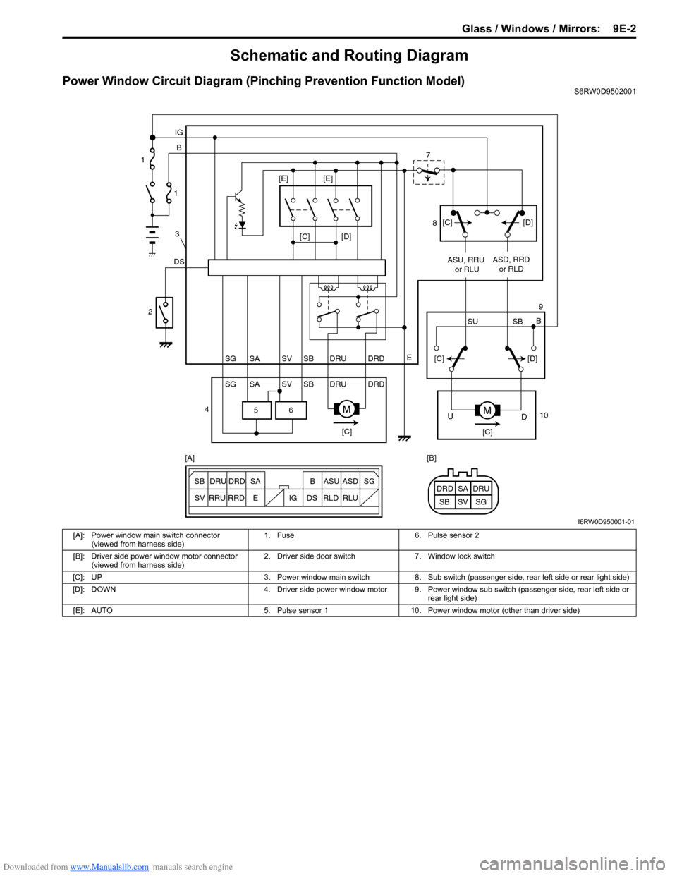
Power Window Circuit Diagram (Pinching Prevention Function Model)S6RW0D9502001
6 5
[C][D]
DSB IG
E
SG SV SBSA DRU DRD
SG SV SBSA DRU DRDASU, RRU
or RLUASD, RRD
or RLD
[C][C]
D U
[C][D]
SU SBB [C][D] [E] [E]
ESG
SV SB SADRU DRD B ASU ASD
RRU
RRDDS IG RLD RLUSG SV SBSA DRU DRD [A] [B] 1
1
3
2
47
8
9
10
I6RW0D950001-01
[A]: Power window main switch connector
(viewed from harness side)1. Fuse 6. Pulse sensor 2
[B]: Driver side power window motor connector
(viewed from harness side)2. Driver side door switch 7. Window lock switch
[C]: UP 3. Power window main switch 8. Sub switch (passenger side, rear left side or rear light side)
[D]: DOWN 4. Driver side power window motor 9. Power window sub switch (passenger side, rear left side or
rear light side)
[E]: AUTO 5. Pulse sensor 1 10. Power window motor (other than driver side)
Page 1404 of 1556
Downloaded from www.Manualslib.com manuals search engine 9E-19 Glass / Windows / Mirrors:
Rear End Door Window Defogger Relay
Inspection
S6RW0D9506018
1) Disconnect negative (–) cable from battery.
2) Remove junction block for inspection of rear end
door window defogger relay.
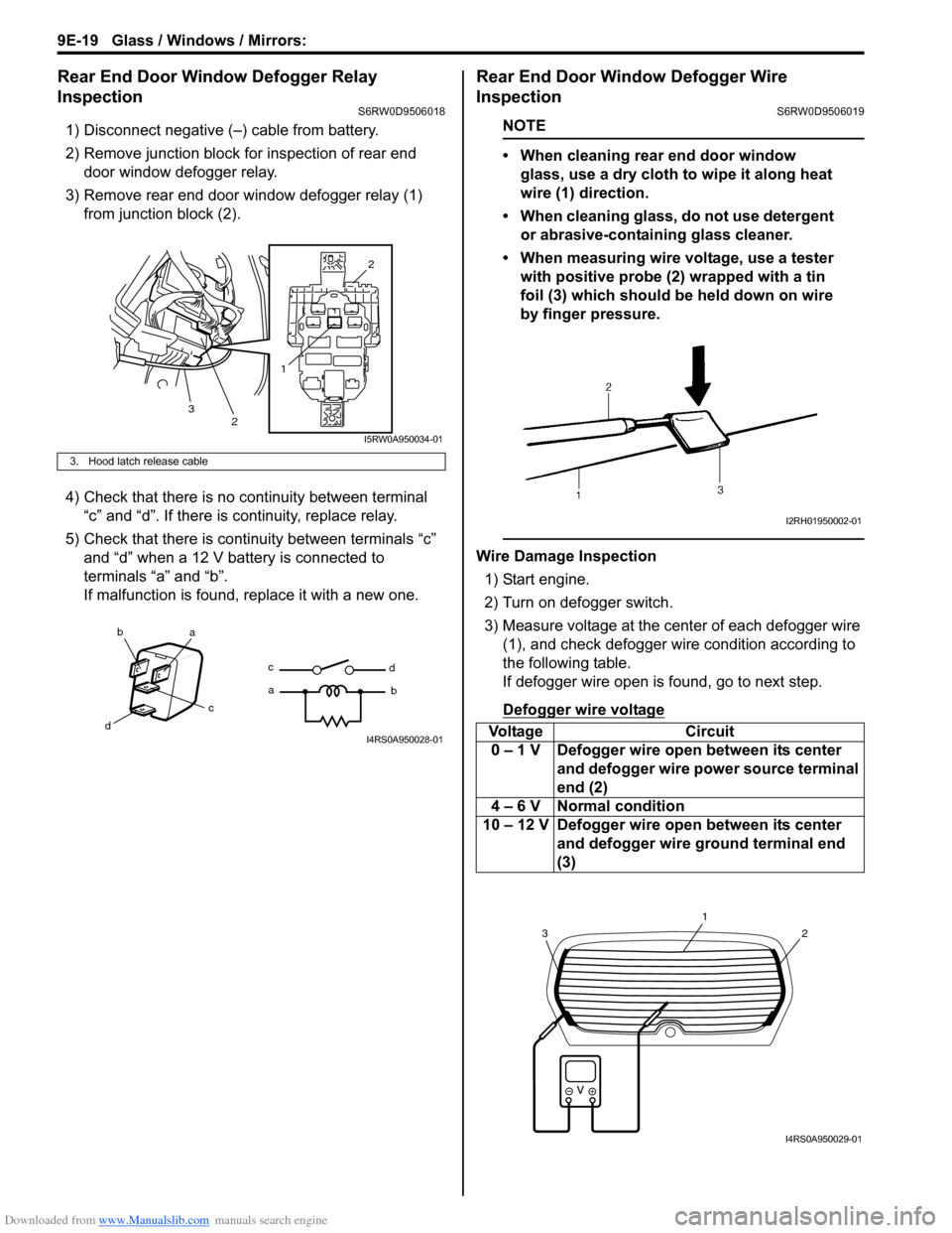
3) Remove rear end door window defogger relay (1)
from junction block (2).
4) Check that there is no continuity between terminal
“c” and “d”. If there is continuity, replace relay.
5) Check that there is continuity between terminals “c”
and “d” when a 12 V battery is connected to
terminals “a” and “b”.
If malfunction is found, replace it with a new one.
Rear End Door Window Defogger Wire
Inspection
S6RW0D9506019
NOTE
• When cleaning rear end door window
glass, use a dry cloth to wipe it along heat
wire (1) direction.
• When cleaning glass, do not use detergent
or abrasive-containing glass cleaner.
• When measuring wire voltage, use a tester
with positive probe (2) wrapped with a tin
foil (3) which should be held down on wire
by finger pressure.
Wire Damage Inspection
1) Start engine.
2) Turn on defogger switch.
3) Measure voltage at the center of each defogger wire
(1), and check defogger wire condition according to
the following table.
If defogger wire open is found, go to next step.
Defogger wire voltage
3. Hood latch release cable
12
2
3
I5RW0A950034-01
ba
c
dc
ad
bI4RS0A950028-01Voltage Circuit
0 – 1 V Defogger wire open between its center
and defogger wire power source terminal
end (2)
4 – 6 V Normal condition
10 – 12 V Defogger wire open between its center
and defogger wire ground terminal end
(3)
I2RH01950002-01
2
1
3
I4RS0A950029-01
Page 1412 of 1556
Downloaded from www.Manualslib.com manuals search engine 9F-1 Security and Locks:
Body, Cab and Accessories
Security and Locks
General Description
Key Coding ConstructionS6RW0D9601001
Key Usage and Identification
Key is used for ignition and door lock cylinders. Key is cut on both edges to make them reversible.
Key identification is obtained from five character key code stamped on key code tag. Using this key code, key code
cutting combination can be determined from a code list (available to owners of key cutting equipment from suppliers).
Rear End Door Opener System DescriptionS6RW0D9601002
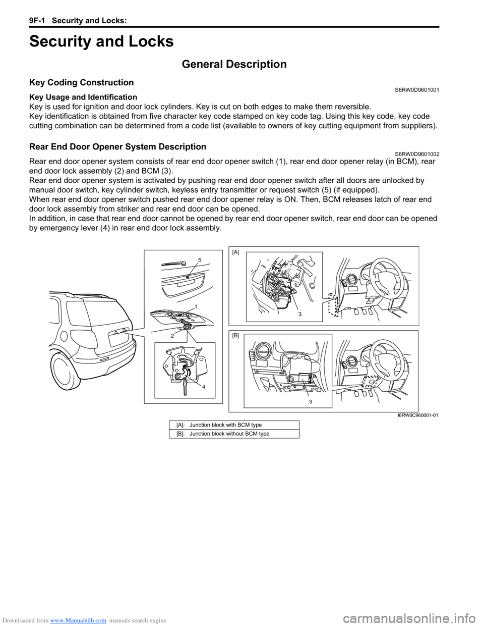
Rear end door opener system consists of rear end door opener switch (1), rear end door opener relay (in BCM), rear
end door lock assembly (2) and BCM (3).
Rear end door opener system is activated by pushing rear end door opener switch after all doors are unlocked by
manual door switch, key cylinder switch, keyless entry transmitter or request switch (5) (if equipped).
When rear end door opener switch pushed rear end door opener relay is ON. Then, BCM releases latch of rear end
door lock assembly from striker and rear end door can be opened.
In addition, in case that rear end door cannot be opened by rear end door opener switch, rear end door can be opened
by emergency lever (4) in rear end door lock assembly.
4
2
1
5
3
[A]
[B]
3
I6RW0C960001-01
[A]: Junction block with BCM type
[B]: Junction block without BCM type
Page 1413 of 1556
Downloaded from www.Manualslib.com manuals search engine Security and Locks: 9F-2
Component Location
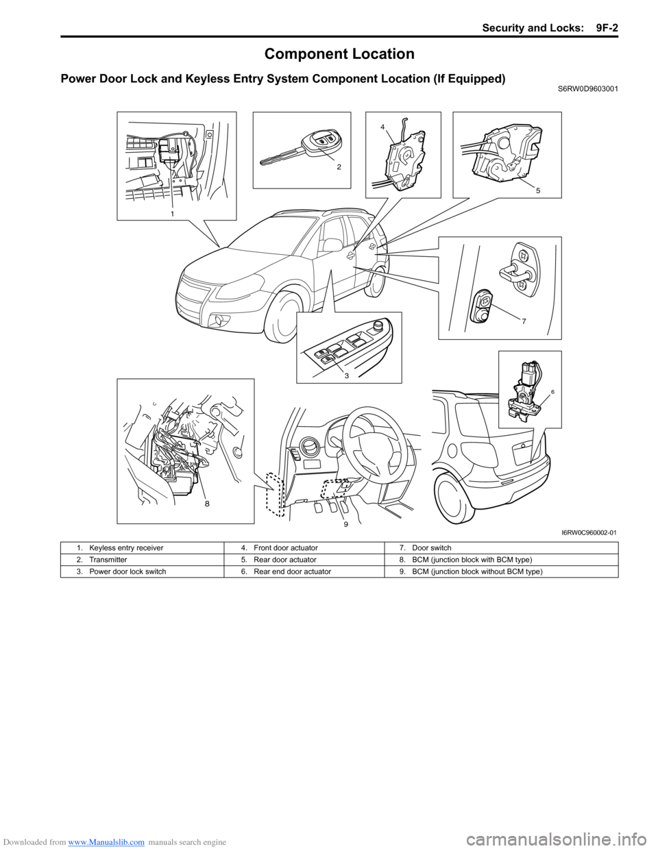
Power Door Lock and Keyless Entry System Component Location (If Equipped)S6RW0D9603001
3
7
4
5
6
1
2
8
9I6RW0C960002-01
1. Keyless entry receiver 4. Front door actuator 7. Door switch
2. Transmitter 5. Rear door actuator 8. BCM (junction block with BCM type)
3. Power door lock switch 6. Rear end door actuator 9. BCM (junction block without BCM type)
Page 1414 of 1556
Downloaded from www.Manualslib.com manuals search engine 9F-3 Security and Locks:
Diagnostic Information and Procedures
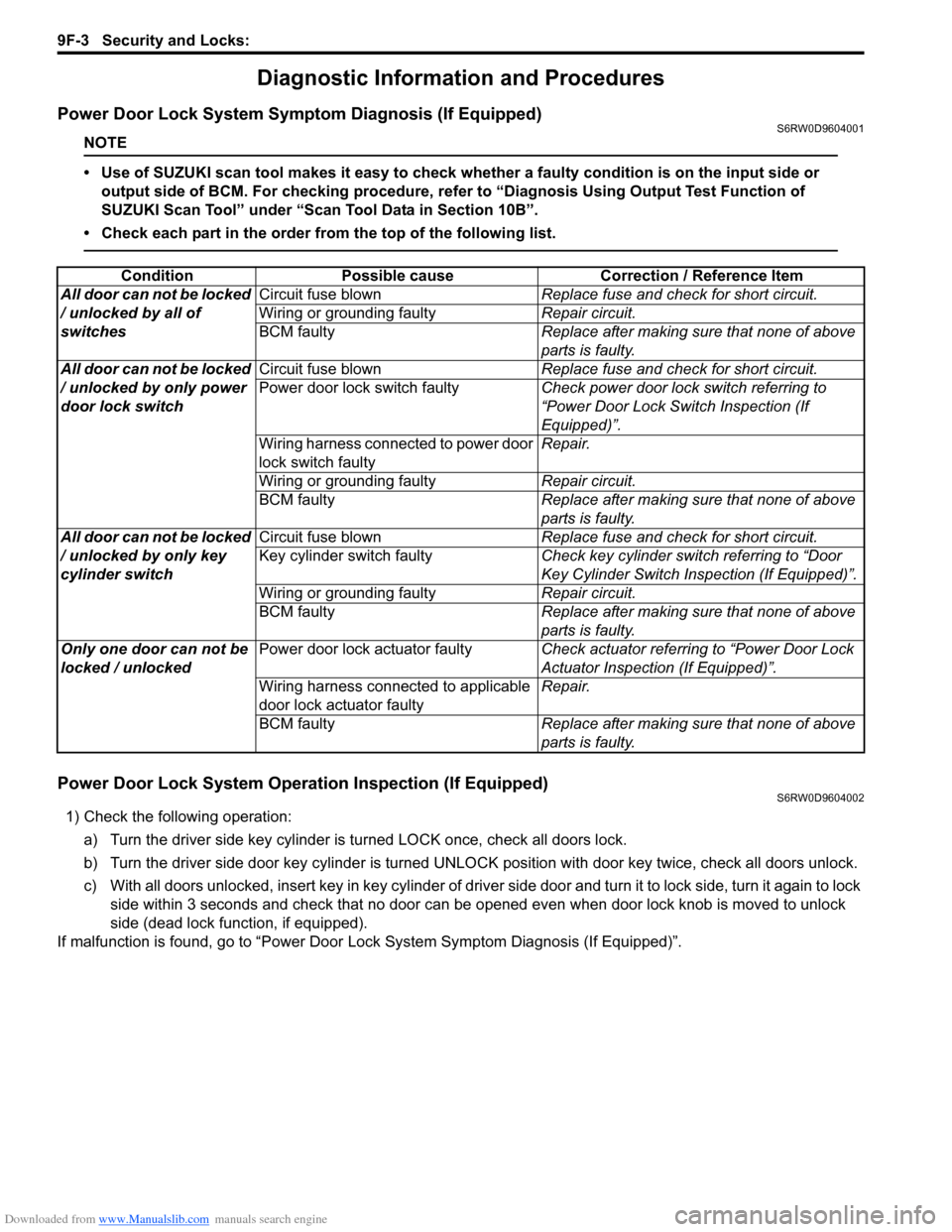
Power Door Lock System Symptom Diagnosis (If Equipped)S6RW0D9604001
NOTE
• Use of SUZUKI scan tool makes it easy to check whether a faulty condition is on the input side or
output side of BCM. For checking procedure, refer to “Diagnosis Using Output Test Function of
SUZUKI Scan Tool” under “Scan Tool Data in Section 10B”.
• Check each part in the order from the top of the following list.
Power Door Lock System Operation Inspection (If Equipped)S6RW0D9604002
1) Check the following operation:
a) Turn the driver side key cylinder is turned LOCK once, check all doors lock.
b) Turn the driver side door key cylinder is turned UNLOCK position with door key twice, check all doors unlock.
c) With all doors unlocked, insert key in key cylinder of driver side door and turn it to lock side, turn it again to lock
side within 3 seconds and check that no door can be opened even when door lock knob is moved to unlock
side (dead lock function, if equipped).
If malfunction is found, go to “Power Door Lock System Symptom Diagnosis (If Equipped)”. Condition Possible cause Correction / Reference Item
All door can not be locked
/ unlocked by all of
switchesCircuit fuse blownReplace fuse and check for short circuit.
Wiring or grounding faultyRepair circuit.
BCM faultyReplace after making sure that none of above
parts is faulty.
All door can not be locked
/ unlocked by only power
door lock switchCircuit fuse blownReplace fuse and check for short circuit.
Power door lock switch faultyCheck power door lock switch referring to
“Power Door Lock Switch Inspection (If
Equipped)”.
Wiring harness connected to power door
lock switch faultyRepair.
Wiring or grounding faultyRepair circuit.
BCM faultyReplace after making sure that none of above
parts is faulty.
All door can not be locked
/ unlocked by only key
cylinder switchCircuit fuse blownReplace fuse and check for short circuit.
Key cylinder switch faultyCheck key cylinder switch referring to “Door
Key Cylinder Switch Inspection (If Equipped)”.
Wiring or grounding faultyRepair circuit.
BCM faultyReplace after making sure that none of above
parts is faulty.
Only one door can not be
locked / unlockedPower door lock actuator faultyCheck actuator referring to “Power Door Lock
Actuator Inspection (If Equipped)”.
Wiring harness connected to applicable
door lock actuator faultyRepair.
BCM faultyReplace after making sure that none of above
parts is faulty.
Page 1415 of 1556
Downloaded from www.Manualslib.com manuals search engine Security and Locks: 9F-4
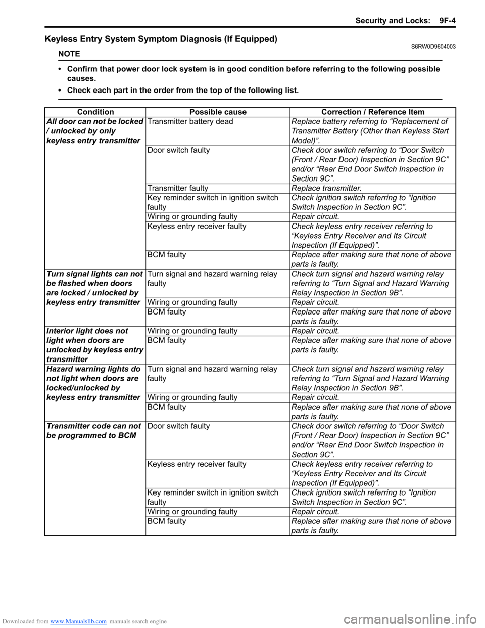
Keyless Entry System Symptom Diagnosis (If Equipped)S6RW0D9604003
NOTE
• Confirm that power door lock system is in good condition before referring to the following possible
causes.
• Check each part in the order from the top of the following list.
Condition Possible cause Correction / Reference Item
All door can not be locked
/ unlocked by only
keyless entry transmitterTransmitter battery deadReplace battery referring to “Replacement of
Transmitter Battery (Other than Keyless Start
Model)”.
Door switch faultyCheck door switch referring to “Door Switch
(Front / Rear Door) Inspection in Section 9C”
and/or “Rear End Door Switch Inspection in
Section 9C”.
Transmitter faultyReplace transmitter.
Key reminder switch in ignition switch
faultyCheck ignition switch referring to “Ignition
Switch Inspection in Section 9C”.
Wiring or grounding faultyRepair circuit.
Keyless entry receiver faultyCheck keyless entry receiver referring to
“Keyless Entry Receiver and Its Circuit
Inspection (If Equipped)”.
BCM faultyReplace after making sure that none of above
parts is faulty.
Turn signal lights can not
be flashed when doors
are locked / unlocked by
keyless entry transmitterTurn signal and hazard warning relay
faultyCheck turn signal and hazard warning relay
referring to “Turn Signal and Hazard Warning
Relay Inspection in Section 9B”.
Wiring or grounding faultyRepair circuit.
BCM faultyReplace after making sure that none of above
parts is faulty.
Interior light does not
light when doors are
unlocked by keyless entry
transmitterWiring or grounding faultyRepair circuit.
BCM faultyReplace after making sure that none of above
parts is faulty.
Hazard warning lights do
not light when doors are
locked/unlocked by
keyless entry transmitterTurn signal and hazard warning relay
faultyCheck turn signal and hazard warning relay
referring to “Turn Signal and Hazard Warning
Relay Inspection in Section 9B”.
Wiring or grounding faultyRepair circuit.
BCM faultyReplace after making sure that none of above
parts is faulty.
Transmitter code can not
be programmed to BCMDoor switch faultyCheck door switch referring to “Door Switch
(Front / Rear Door) Inspection in Section 9C”
and/or “Rear End Door Switch Inspection in
Section 9C”.
Keyless entry receiver faultyCheck keyless entry receiver referring to
“Keyless Entry Receiver and Its Circuit
Inspection (If Equipped)”.
Key reminder switch in ignition switch
faultyCheck ignition switch referring to “Ignition
Switch Inspection in Section 9C”.
Wiring or grounding faultyRepair circuit.
BCM faultyReplace after making sure that none of above
parts is faulty.
Page 1416 of 1556
Downloaded from www.Manualslib.com manuals search engine 9F-5 Security and Locks:
Keyless Entry System Operation Inspection (If
Equipped)
S6RW0D9604004
NOTE
When performing the this inspection, make
sure to have any of the door once opened /
closed after the ignition key has been
removed from the ignition key cylinder.
1) Confirm that power door lock system operates
normally, refer to “Power Door Lock System
Operation Inspection (If Equipped)”.
2) All doors are closed and unlocked.
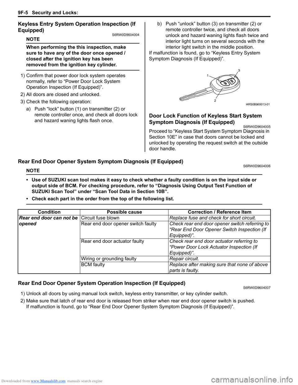
3) Check the following operation:
a) Push “lock” button (1) on transmitter (2) or
remote controller once, and check all doors lock
and hazard waning lights flash once.b) Push “unlock” button (3) on transmitter (2) or
remote controller twice, and check all doors
unlock and hazard waning lights flash twice and
interior light turns on several seconds with the
interior light switch in the middle position.
If malfunction is found, go to “Keyless Entry System
Symptom Diagnosis (If Equipped)”.
Door Lock Function of Keyless Start System
Symptom Diagnosis (If Equipped)
S6RW0D9604005
Proceed to “Keyless Start System Symptom Diagnosis in
Section 10E” in case that doors cannot be locked and
unlocked by operating the request switch at the outside
door handle.
Rear End Door Opener System Symptom Diagnosis (If Equipped)S6RW0D9604006
NOTE
• Use of SUZUKI scan tool makes it easy to check whether a faulty condition is on the input side or
output side of BCM. For checking procedure, refer to “Diagnosis Using Output Test Function of
SUZUKI Scan Tool” under “Scan Tool Data in Section 10B”.
• Check each part in the order from the top of the following list.
Rear End Door Opener System Operation Inspection (If Equipped)S6RW0D9604007
1) Unlock all doors by using manual lock switch, keyless entry transmitter, or key cylinder switch.
2) Make sure that latch of rear end door is released from striker when rear end door opener switch is pushed.
If malfunction is found, go to “Rear End Door Opener System Symptom Diagnosis (If Equipped)”.
1
3
2I4RS0B960013-01
Condition Possible cause Correction / Reference Item
Rear end door can not be
openedCircuit fuse blownReplace fuse and check for short circuit.
Rear end door opener switch faultyCheck rear end door opener switch referring to
“Rear End Door Opener Switch Inspection (If
Equipped)”.
Rear end door actuator faultyCheck rear end door actuator referring to
“Power Door Lock Actuator Inspection (If
Equipped)”.
Wiring or grounding faultyRepair circuit.
BCM faultyReplace after making sure that none of above
parts is faulty.
Page 1417 of 1556
Downloaded from www.Manualslib.com manuals search engine Security and Locks: 9F-6
Repair Instructions
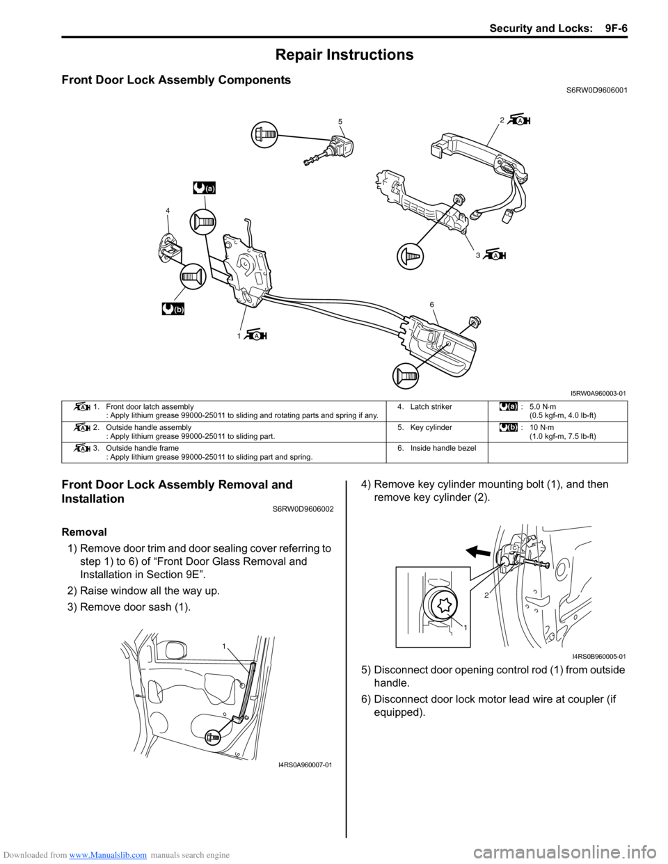
Front Door Lock Assembly ComponentsS6RW0D9606001
Front Door Lock Assembly Removal and
Installation
S6RW0D9606002
Removal
1) Remove door trim and door sealing cover referring to
step 1) to 6) of “Front Door Glass Removal and
Installation in Section 9E”.
2) Raise window all the way up.
3) Remove door sash (1).4) Remove key cylinder mounting bolt (1), and then
remove key cylinder (2).
5) Disconnect door opening control rod (1) from outside
handle.
6) Disconnect door lock motor lead wire at coupler (if
equipped).
(a)
(b)
5
3
6
1 4
2
I5RW0A960003-01
1. Front door latch assembly
: Apply lithium grease 99000-25011 to sliding and rotating parts and spring if any.4. Latch striker : 5.0 N⋅m
(0.5 kgf-m, 4.0 lb-ft)
2. Outside handle assembly
: Apply lithium grease 99000-25011 to sliding part.5. Key cylinder : 10 N⋅m
(1.0 kgf-m, 7.5 lb-ft)
3. Outside handle frame
: Apply lithium grease 99000-25011 to sliding part and spring.6. Inside handle bezel
1
I4RS0A960007-01
12
I4RS0B960005-01