2006 SUZUKI SX4 wheel sensor
[x] Cancel search: wheel sensorPage 465 of 1556

Downloaded from www.Manualslib.com manuals search engine Rear Suspension: 2C-6
Rear Axle Removal and InstallationS6RW0D2306007
CAUTION!
Do not drop brake fluid onto painted surface.
Painted surfaces will be damaged.
Removal
1) Hoist vehicle and remove exhaust center pipe and
muffler.
2) Disconnect rear height sensor link (if equipped) from
rear axle referring to “Height Sensor Removal and
Installation (If Equipped) in Section 9B”.
3) Remove rear wheel, rear brake drum and rear wheel
hub referring to “Removal” under “Rear Wheel Hub
Assembly Removal and Installation”.
4) Disconnect brake pipe (1) from brake flexible hoses
(2) and remove E-rings (3).
5) Remove coil springs referring to “Rear Coil Spring
Removal and Installation”.
6) Disconnect wheel speed sensor clamp (1) and
parking brake cable nuts (2) from rear axle.
7) While supporting rear axle at both ends, remove rear
axle bolts and then remove rear axle from chassis by
lowering floor jack gradually.
8) Remove brake pipes from rear axle, if necessary.Installation
CAUTION!
Never reuse rear axle bolts and rear wheel
hub mounting bolts.
1) Install brake pipes to rear axle, if removed.
2) Using floor jacks, install rear axle and new rear axle
bolts (1) and tighten bolts temporarily.
3) Install coil spring referring to “Rear Coil Spring
Removal and Installation”.
4) Install rear wheel hub and wheel speed sensor
referring to “Installation” under “Rear Wheel Hub
Assembly Removal and Installation”.
5) Connect brake flexible hoses (1) to bracket on rear
axle with E-ring (2) and tighten brake pipe flare nuts
(3) to specified torque.
Tightening torque
Brake pipe flare nut (a): 16 N·m (1.6 kgf-m, 11.5
lb-ft)
1 3
2
I5RW0A230013-01
2
1
I5RW0A230015-01
1
I5RW0A230017-01
2
1
3,(a)
I5RW0A230019-01
Page 466 of 1556

Downloaded from www.Manualslib.com manuals search engine 2C-7 Rear Suspension:
6) Connect rear height sensor link (if equipped) to rear
axle referring to “Height Sensor Removal and
Installation (If Equipped) in Section 9B”.
7) Install exhaust center pipe and muffler.
8) After installing removed parts, bleed air from brake
system referring to “Air Bleeding of Brake System in
Section 4A”. And then adjust parking brake cable
referring to “Parking Brake Inspection and
Adjustment in Section 4D”.
9) Install wheel and tighten wheel nuts to specified
torque.
Tightening torque
Wheel nut: 85 N·m (8.5 kgf-m, 61.5 lb-ft)
10) Lower hoist and bounce vehicle up and down
several times to stabilize suspension.
11) Tightening shock absorber lower nuts and rear axle
bolts to specified torque.
NOTE
When tightening these nuts and bolts, be
sure that vehicle is not on hoist and in
unloaded condition.
Tightening torque
Rear shock absorber lower nut: 90 N·m (9.0 kgf-
m, 65.0 lb-ft)
Rear axle bolt: 73 N·m (7.3 kgf-m, 53.0 lb-ft)
12) Perform brake test (foot brake and parking brake).
13) Check each installed parts for brake fluid leakage.
Rear Axle and Coil Spring InspectionS6RW0D2306009
• Inspect for cracks, deformation or damage.
• Inspect bushing for damage, wear or breakage.
Replace any defective part.
Rear Axle Bush InspectionS6RW0D2306010
Inspect for cracks, deformation or damage. If necessary,
replace rear axle assembly.
Rear Wheel Disc, Bolt and Bearing InspectionS6RW0D2306011
• Check tightness of wheel nuts and, if necessary,
retighten to specified torque.
• Check wheel disc deformation, damage, crack and
etc.
Replace defective disc with new one.
• Check installation face inside of wheel disc for rust.
As rust affects adversely, remove it thoroughly.
Tightening torque
Wheel nut: 85 N·m (8.5 kgf-m, 61.5 lb-ft)
• Check wear of wheel bearings. When measuring
thrust play, apply a dial gauge to axle shaft center.
When the thrust play exceeds limit, replace bearing.
Rear wheel bearing thrust play
Limit: 0.1 mm (0.004 in.)
• Check noise and smooth rotation of wheel by rotating
wheel. If it is defective, replace bearing.
(a)I5RW0A230022-01
I3RM0A230049-01
I3RM0A230050-01
Page 467 of 1556

Downloaded from www.Manualslib.com manuals search engine Rear Suspension: 2C-8
Rear Wheel Hub Assembly Removal and
Installation
S6RW0D2306012
CAUTION!
Do not allow brake fluid to get on painted
surfaces. Painted surface will be damaged.
Removal
1) Hoist vehicle. Then remove rear wheel and brake
drum.
2) For 4WD model, remove rear drive shaft referring to
“Rear Drive Shaft Assembly Removal and
Installation in Section 3A”.
3) Remove rear brake shoe.
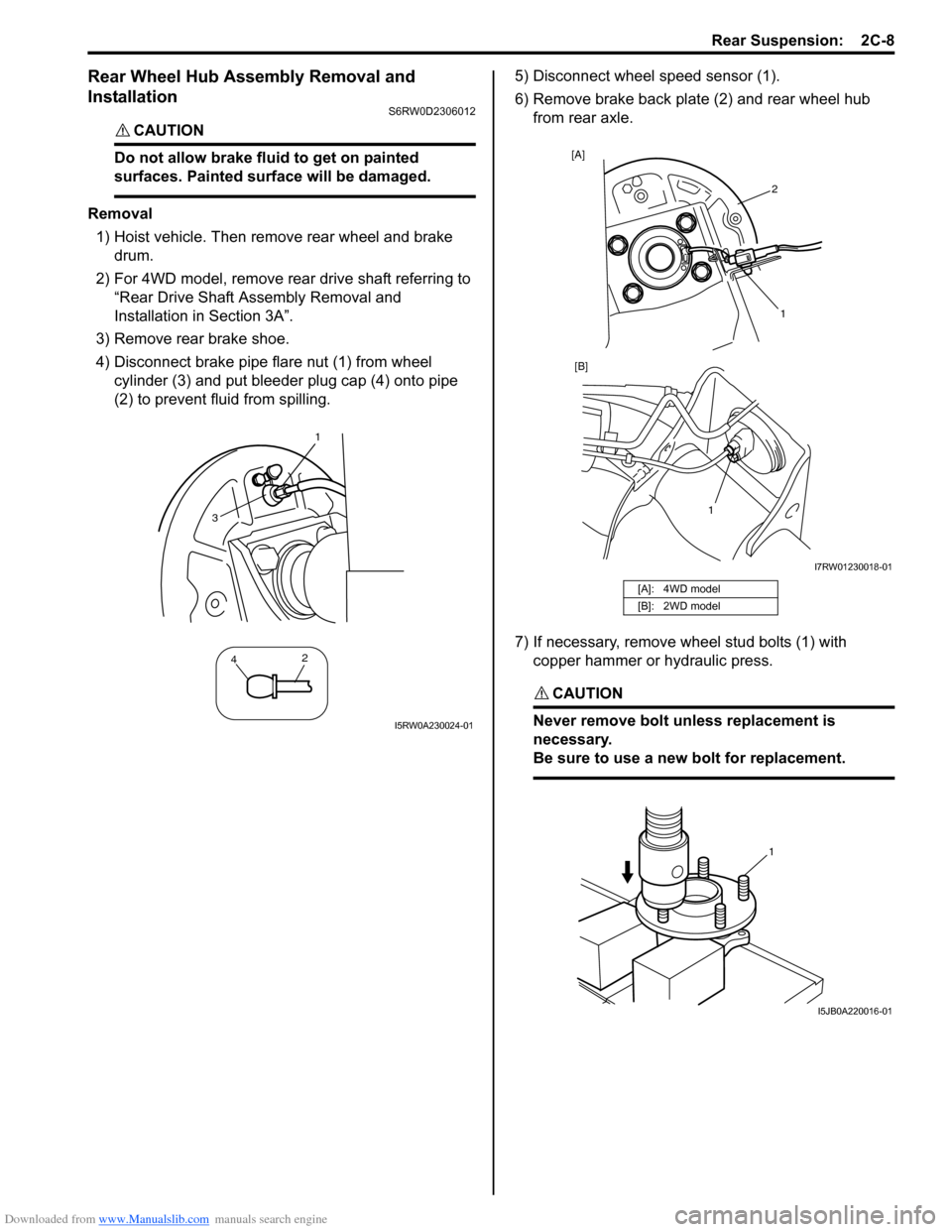
4) Disconnect brake pipe flare nut (1) from wheel
cylinder (3) and put bleeder plug cap (4) onto pipe
(2) to prevent fluid from spilling.5) Disconnect wheel speed sensor (1).
6) Remove brake back plate (2) and rear wheel hub
from rear axle.
7) If necessary, remove wheel stud bolts (1) with
copper hammer or hydraulic press.
CAUTION!
Never remove bolt unless replacement is
necessary.
Be sure to use a new bolt for replacement.
1
42
3
I5RW0A230024-01
[A]: 4WD model
[B]: 2WD model
2 [A]
1 [B]
1
I7RW01230018-01
1
I5JB0A220016-01
Page 468 of 1556

Downloaded from www.Manualslib.com manuals search engine 2C-9 Rear Suspension:
Installation
1) Insert wheel stud bolt (1) in hub hole. Rotate wheel
stud bolt slowly to assure that serrations are aligned
with those made by original bolt.
2) Install brake back plate, rear wheel hub and new rear
wheel hub bolts and then tighten rear wheel hub
mounting bolts to specified torque.
CAUTION!
Use new rear wheel hub mounting bolts.
Tightening torque
Rear wheel hub mounting bolt: 73 N·m (7.3 kgf-
m, 53.0 lb-ft)
3) For 4WD model, install rear drive shaft referring to
“Rear Drive Shaft Assembly Removal and
Installation in Section 3A”.
CAUTION!
Never reuse rear drive shaft nut.
Tightening torque
Drive shaft nut (a): 175 N·m (17.5 kgf-m, 127.0
lb-ft)4) Connect wheel speed sensor and tighten wheel
speed sensor bolt (2WD model) to specified torque.
Tightening torque
Wheel speed sensor bolt : 11 N·m (1.1 kgf-m, 8.0
lb-ft)
5) Connect brake pipe (1) to wheel cylinder and tighten
brake pipe flare nut to specified torque.
Tightening torque
Brake pipe flare nut (a): 16 N·m (1.6 kgf-m, 11.5
lb-ft)
6) Install brake drum referring to Step 1) and 2) of
“Installation” under “Rear Brake Drum Removal and
Installation in Section 4C”.
7) Fill reservoir with brake fluid and bleed brake
system. For bleeding operation, see “Air Bleeding of
Brake System in Section 4A”.
8) Install wheel and tighten wheel nuts to specified
torque.
Tightening torque
Wheel nut: 85 N·m (8.5 kgf-m, 61.5 lb-ft)
9) Upon completion of all jobs, depress brake pedal
with about 300 N (30 kg, 66 lbs) load at least 3 times
so as to obtain proper drum-to-shoe clearance.
Adjust parking brake cable. For adjustment, see
“Parking Brake Inspection and Adjustment in Section
4D”.
10) Check to ensure that brake drum is free from
dragging and proper braking is obtained.
11) Perform brake test (foot brake and parking brake).
12) Check each installed part for fluid leakage.
1
I5JB0A220017-01
1,(a)
1
I7RW01230012-01
(a)
1
I5RW0A230018-01
Page 469 of 1556

Downloaded from www.Manualslib.com manuals search engine Rear Suspension: 2C-10
Specifications
Tightening Torque SpecificationsS6RW0D2307001
NOTE
The specified tightening torque is also described in the following.
“Rear Suspension Components”
Reference:
For the tightening torque of fastener not specified in this section, refer to “Fasteners Information in Section 0A”. Fastening partTightening torque
Note
N⋅mkgf-mlb-ft
Wheel nut 85 8.5 61.5�) / �) / �) / �) / �)
Rear shock absorber upper nut 30 3.0 22.0�)
Rear shock absorber lower nut 90 9.0 65.0�) / �) / �)
Rear axle bolt 73 7.3 53.0�) / �)
Brake pipe flare nut 16 1.6 11.5�) / �)
Rear wheel hub mounting bolt 73 7.3 53.0�)
Drive shaft nut 175 17.5 127.0�)
Wheel speed sensor bolt 11 1.1 8.0�)
Page 482 of 1556

Downloaded from www.Manualslib.com manuals search engine 3A-3 Drive Shaft / Axle: Front
Front Drive Shaft Assembly On-Vehicle
Inspection
S6RW0D3116002
• Check boots for breakage or deterioration.
• Check wheel side joint for rattle or smooth rotation.
• Check differential side (or center shaft side) joint for
smooth rotation.
If any abnormality is found, replace.
Front Drive Shaft Assembly Removal and
Installation
S6RW0D3116003
Removal
1) Hoist vehicle and remove front wheel.
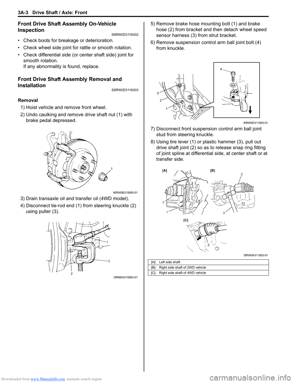
2) Undo caulking and remove drive shaft nut (1) with
brake pedal depressed.
3) Drain transaxle oil and transfer oil (4WD model).
4) Disconnect tie-rod end (1) from steering knuckle (2)
using puller (3).5) Remove brake hose mounting bolt (1) and brake
hose (2) from bracket and then detach wheel speed
sensor harness (3) from strut bracket.
6) Remove suspension control arm ball joint bolt (4)
from knuckle.
7) Disconnect front suspension control arm ball joint
stud from steering knuckle.
8) Using tire lever (1) or plastic hammer (3), pull out
drive shaft joint (2) so as to release snap ring fitting
of joint spline at differential side, at center shaft or at
transfer side.
I6RW0B310005-01
I3RM0A310003-01
[A]: Left side shaft
[B]: Right side shaft of 2WD vehicle
[C]: Right side shaft of 4WD vehicle
I6RW0D311003-01
I5RW0A311003-01
Page 499 of 1556

Downloaded from www.Manualslib.com manuals search engine Differential: 3B-2
General Description
Rear Differential DescriptionS6RW0D3201001
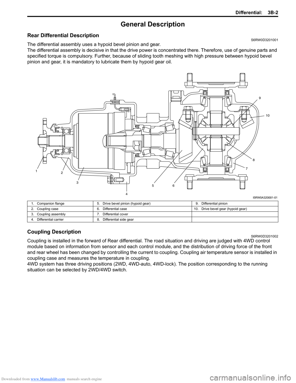
The differential assembly uses a hypoid bevel pinion and gear.
The differential assembly is decisive in that the drive power is concentrated there. Therefore, use of genuine parts and
specified torque is compulsory. Further, because of sliding tooth meshing with high pressure between hypoid bevel
pinion and gear, it is mandatory to lubricate them by hypoid gear oil.
Coupling DescriptionS6RW0D3201002
Coupling is installed in the forward of Rear differential. The road situation and driving are judged with 4WD control
module based on information from sensor and each control module, and the distribution of driving force of the front
and rear wheel has been changed by controlling the current to coupling. Coupling air temperature sensor is installed in
coupling case and measures the temperature in coupling.
4WD system has three driving positions (2WD, 4WD-auto, 4WD-lock). The position corresponding to the running
situation can be selected by 2WD/4WD switch.
1
2
3
4567810 9
I5RW0A320001-01
1. Companion flange 5. Drive bevel pinion (hypoid gear) 9. Differential pinion
2. Coupling case 6. Differential case 10. Drive bevel gear (hypoid gear)
3. Coupling assembly 7. Differential cover
4. Differential carrier 8. Differential side gear
Page 510 of 1556

Downloaded from www.Manualslib.com manuals search engine 3B-13 Differential:
Scan Tool DataS6RW0D3204009
Scan Tool Data Definitions
Accel pedal Pos (Accelerator pedal position) (%)
Accelerator pedal opening ratio detected by signal on
CAN communication line fed from ECM.
Engine Speed (RPM)
This parameter indicates engine revolution calculated by
4WD control module.
4WD mode (2WD / AUTO / LOCK / ABS mode / Yaw
cont / ESP® req)
This parameter indicates 4WD mode according to 2WD/
4WD switch signal status detected by 4WD control
module.
4WD current (A)
This parameter indicates input current of coupling
assembly.
Battery voltage (V)
This parameter indicates battery voltage detected by
4WD control module.Coupling temp (°C, °F)
Coupling temperature detected by coupling air
temperature sensor installed in coupling assembly.
Wheel speed (F), Wheel speed (R) (km/h, mph)
Wheel speed is an ABS / ESP® control module internal
parameter. It is computed by reference pulses from the
wheel speed sensor.
F-R Wheel speed diff (Front-rear wheel speed
differential) (rpm)
This parameter indicates rotation difference between
front wheel and rear wheel detected by 4WD control
module.
4WD duty (%)
This parameter indicates operation rate of coupling
assembly. Scan tool data Vehicle conditionNormal condition / reference
values
�) Accel pedal PosIgnition switch ON after
warmed up engineAccelerator pedal released 0 – 5%
Accelerator pedal depressed
fully90 – 100%
�) Engine speed At engine idle speed Engine idle speed is display
�) 4WD mode2WD/4WD switch selected to 2WD position 2WD
2WD/4WD switch selected to AUTO position AUTO
2WD/4WD switch selected to LOCK position LOCK
ABS operating ABS mode
Ignition switch ON and engine stop Relay off
Stability control operating Yaw cont
ESP® operating ESP® mode
�) 4WD current Engine running 0 – 200 mA
�) Battery voltage At engine idle speed 10 – 14 V
�) Coupling temp Engine running –40 °C – 100 °C (–40 °F – 212 °F)
�) Wheel speed (F) Vehicle stop 0 km/h, 0 MPH
�) Wheel speed (R) Vehicle stop 0 km/h, 0 MPH
�) F-R Wheel speed
DiffVehicle stop 0 rpm
�) 4WD dutyIgnition switch ON and 2WD/4WD switch selected to
2WD position0%