2006 SUZUKI SX4 warning lights
[x] Cancel search: warning lightsPage 1475 of 1556
Downloaded from www.Manualslib.com manuals search engine Body Electrical Control System: 10B-2
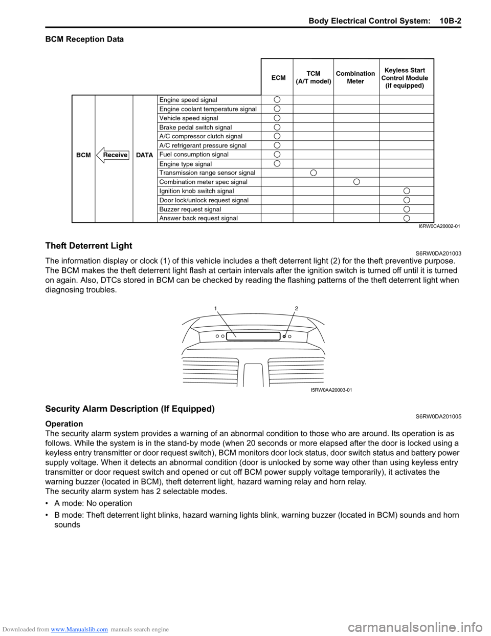
BCM Reception Data
Theft Deterrent LightS6RW0DA201003
The information display or clock (1) of this vehicle includes a theft deterrent light (2) for the theft preventive purpose.
The BCM makes the theft deterrent light flash at certain intervals after the ignition switch is turned off until it is turned
on again. Also, DTCs stored in BCM can be checked by reading the flashing patterns of the theft deterrent light when
diagnosing troubles.
Security Alarm Description (If Equipped)S6RW0DA201005
Operation
The security alarm system provides a warning of an abnormal condition to those who are around. Its operation is as
follows. While the system is in the stand-by mode (when 20 seconds or more elapsed after the door is locked using a
keyless entry transmitter or door request switch), BCM monitors door lock status, door switch status and battery power
supply voltage. When it detects an abnormal condition (door is unlocked by some way other than using keyless entry
transmitter or door request switch and opened or cut off BCM power supply voltage temporarily), it activates the
warning buzzer (located in BCM), theft deterrent light, hazard warning relay and horn relay.
The security alarm system has 2 selectable modes.
• A mode: No operation
• B mode: Theft deterrent light blinks, hazard warning lights blink, warning buzzer (located in BCM) sounds and horn
sounds
Engine speed signal
Vehicle speed signal Engine coolant temperature signal
Brake pedal switch signal
A/C refrigerant pressure signal
Fuel consumption signal A/C compressor clutch signal
Engine type signal
Transmission range sensor signal
Combination meter spec signal
Ignition knob switch signal
Door lock/unlock request signal
Buzzer request signal
Answer back request signal DATA BCM
Receive
Combination
Meter TCM
(A/T model)Keyless Start
Control Module
(if equipped) ECM
I6RW0CA20002-01
12
I5RW0AA20003-01
Page 1511 of 1556
Downloaded from www.Manualslib.com manuals search engine Immobilizer Control System: 10C-9
Immobilizer Indicator Light Does Not Come ON with Ignition Switch ON and Engine StopS6RW0DA304006
Wiring Diagram
Refer to “Immobilizer Control System Wiring Circuit Diagram”.
Circuit Description
When the ignition switch is turned ON, ECM transmits the indication ON signal to the combination meter to turn ON the
immobilizer indicator light in case that there is not any problem with the immobilizer control system. Then, the
combination meter turns ON the light. When the engine is started up, ECM transmits the indication OFF signal to the
combination meter to turn OFF the light. Then, the combination meter turns OFF the immobilizer indicator light.
However, in case that there is some trouble with the immobilizer control system, the immobilizer indicator light flashes
ON and OFF when the ignition switch is turned ON.
Troubleshooting
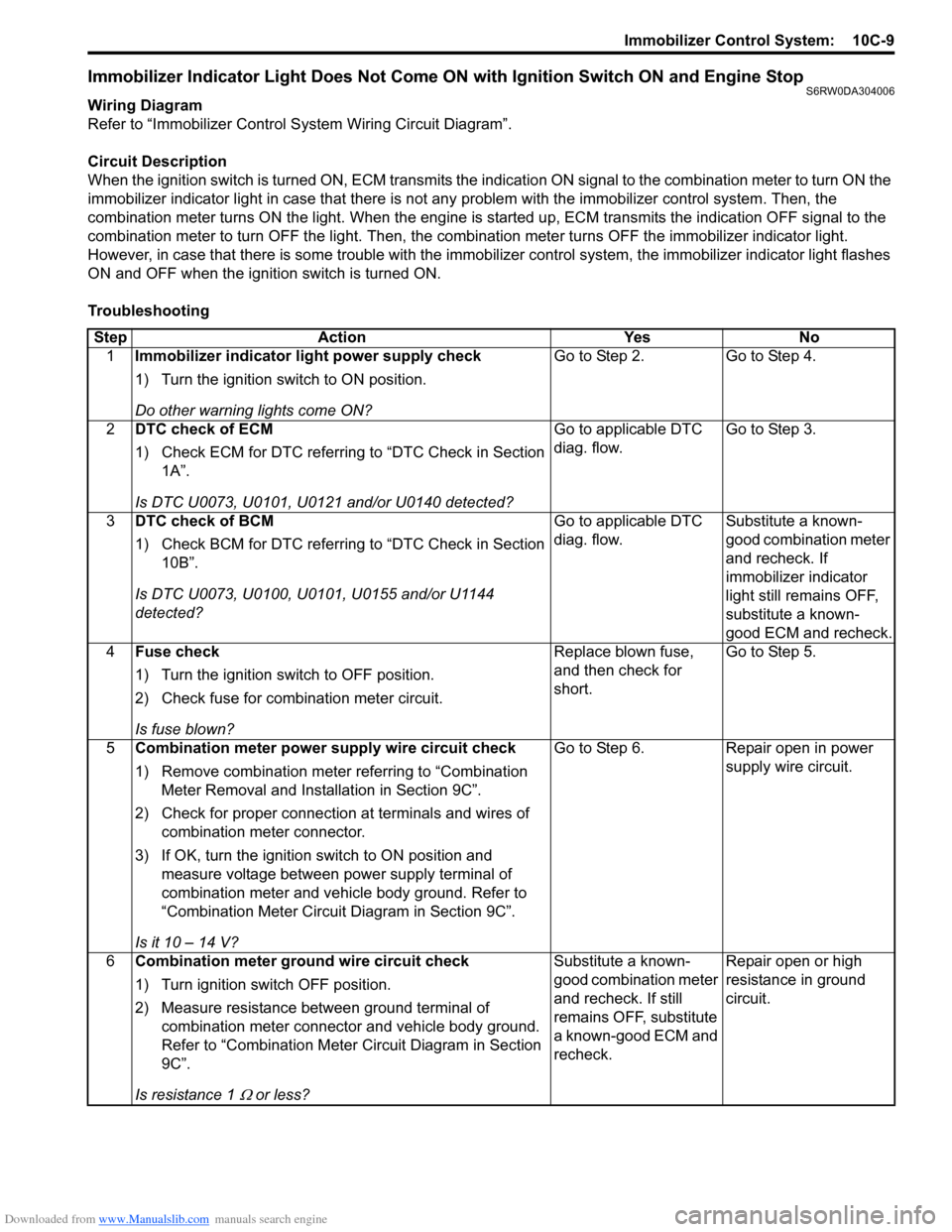
Step Action Yes No
1Immobilizer indicator light power supply check
1) Turn the ignition switch to ON position.
Do other warning lights come ON?Go to Step 2. Go to Step 4.
2DTC check of ECM
1) Check ECM for DTC referring to “DTC Check in Section
1A”.
Is DTC U0073, U0101, U0121 and/or U0140 detected?Go to applicable DTC
diag. flow.Go to Step 3.
3DTC check of BCM
1) Check BCM for DTC referring to “DTC Check in Section
10B”.
Is DTC U0073, U0100, U0101, U0155 and/or U1144
detected?Go to applicable DTC
diag. flow.Substitute a known-
good combination meter
and recheck. If
immobilizer indicator
light still remains OFF,
substitute a known-
good ECM and recheck.
4Fuse check
1) Turn the ignition switch to OFF position.
2) Check fuse for combination meter circuit.
Is fuse blown?Replace blown fuse,
and then check for
short.Go to Step 5.
5Combination meter power supply wire circuit check
1) Remove combination meter referring to “Combination
Meter Removal and Installation in Section 9C”.
2) Check for proper connection at terminals and wires of
combination meter connector.
3) If OK, turn the ignition switch to ON position and
measure voltage between power supply terminal of
combination meter and vehicle body ground. Refer to
“Combination Meter Circuit Diagram in Section 9C”.
Is it 10 – 14 V?Go to Step 6. Repair open in power
supply wire circuit.
6Combination meter ground wire circuit check
1) Turn ignition switch OFF position.
2) Measure resistance between ground terminal of
combination meter connector and vehicle body ground.
Refer to “Combination Meter Circuit Diagram in Section
9C”.
Is resistance 1
Ω or less?Substitute a known-
good combination meter
and recheck. If still
remains OFF, substitute
a known-good ECM and
recheck.Repair open or high
resistance in ground
circuit.
Page 1524 of 1556
Downloaded from www.Manualslib.com manuals search engine 10E-2 Keyless Start System:
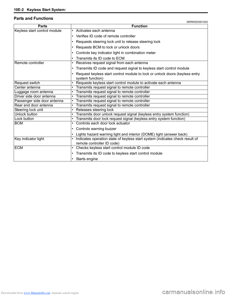
Parts and FunctionsS6RW0DA501002
Parts Function
Keyless start control module • Activates each antenna
• Verifies ID code of remote controller
• Requests steering lock unit to release steering lock
• Requests BCM to lock or unlock doors
• Controls key indicator light in combination meter
• Transmits its ID code to ECM
Remote controller • Receives request signal from each antenna
• Transmits ID code and request signal to keyless start control module
• Request keyless start control module to lock or unlock doors (keyless entry
system function)
Request switch • Requests keyless start control module to activate each antenna
Center antenna • Transmits request signal to remote controller
Luggage room antenna • Transmits request signal to remote controller
Driver side door antenna • Transmits request signal to remote controller
Passenger side door antenna • Transmits request signal to remote controller
Rear end door antenna • Transmits request signal to remote controller
Steering lock unit • Releases steering lock
Unlock button • Transmits door unlock request signal (keyless entry system function)
Lock button • Transmits door lock request signal (keyless entry system function)
BCM • Controls each door lock actuator
• Controls warning buzzer
• Lights hazard warning light and interior (DOME) light (answer back)
Key indicator light • Indicates operation state of keyless start system (indicates check result of
remote controller ID code)
ECM • Checks keyless start control module ID code
• Transmits its ID code to keyless start control module
• Starts engine
Page 1542 of 1556
Downloaded from www.Manualslib.com manuals search engine 10E-20 Keyless Start System:
No DTC Detection After Performing DTC CheckS6RW0DA504014
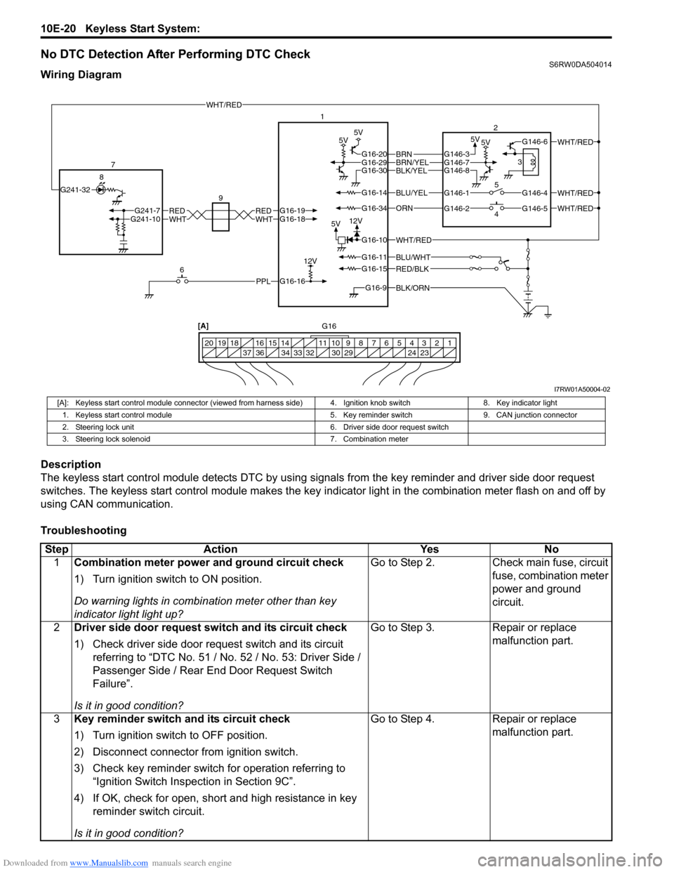
Wiring Diagram
Description
The keyless start control module detects DTC by using signals from the key reminder and driver side door request
switches. The keyless start control module makes the key indicator light in the combination meter flash on and off by
using CAN communication.
Troubleshooting
BLK/ORNG16-9
G16-15
G16-14
G16-16
G16-20G16-29G16-30
G16-10
G16-34
G16-11BLU/WHT
WHT/RED
WHT/RED
WHT/RED
PPL
RED/BLK
5V5V 5V5V
5V12V
12VWHTREDWHTREDG16-18G16-19G241-10G241-7
BLU/YEL
ORN
BLK/YELBRN/YELBRNG146-3
G146-1
G146-2G146-5
G146-4
G146-6
G146-7G146-8
WHT/RED
WHT/RED
G241-32
6 7
81
2
4 53
20 12 3 4 5 6 7 8 9 10 11 14 15 16
36 34 33 32 30 29 24 23 37 18 19
[A]
9
G16
I7RW01A50004-02
[A]: Keyless start control module connector (viewed from harness side) 4. Ignition knob switch 8. Key indicator light
1. Keyless start control module 5. Key reminder switch 9. CAN junction connector
2. Steering lock unit 6. Driver side door request switch
3. Steering lock solenoid 7. Combination meter
Step Action Yes No
1Combination meter power and ground circuit check
1) Turn ignition switch to ON position.
Do warning lights in combination meter other than key
indicator light light up?Go to Step 2. Check main fuse, circuit
fuse, combination meter
power and ground
circuit.
2Driver side door request switch and its circuit check
1) Check driver side door request switch and its circuit
referring to “DTC No. 51 / No. 52 / No. 53: Driver Side /
Passenger Side / Rear End Door Request Switch
Failure”.
Is it in good condition?Go to Step 3. Repair or replace
malfunction part.
3Key reminder switch and its circuit check
1) Turn ignition switch to OFF position.
2) Disconnect connector from ignition switch.
3) Check key reminder switch for operation referring to
“Ignition Switch Inspection in Section 9C”.
4) If OK, check for open, short and high resistance in key
reminder switch circuit.
Is it in good condition?Go to Step 4. Repair or replace
malfunction part.
Page 1544 of 1556
Downloaded from www.Manualslib.com manuals search engine 10E-22 Keyless Start System:
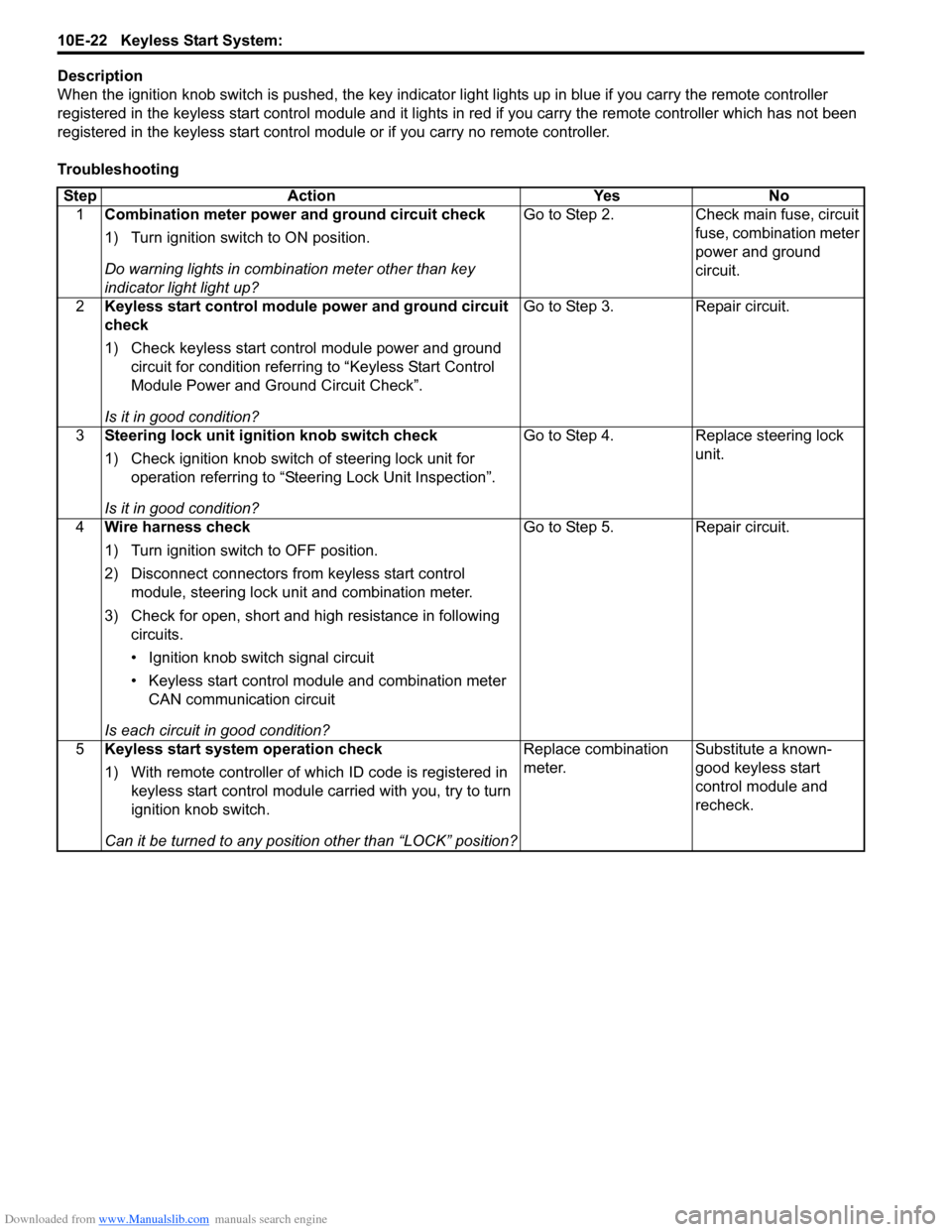
Description
When the ignition knob switch is pushed, the key indicator light lights up in blue if you carry the remote controller
registered in the keyless start control module and it lights in red if you carry the remote controller which has not been
registered in the keyless start control module or if you carry no remote controller.
Troubleshooting
Step Action Yes No
1Combination meter power and ground circuit check
1) Turn ignition switch to ON position.
Do warning lights in combination meter other than key
indicator light light up?Go to Step 2. Check main fuse, circuit
fuse, combination meter
power and ground
circuit.
2Keyless start control module power and ground circuit
check
1) Check keyless start control module power and ground
circuit for condition referring to “Keyless Start Control
Module Power and Ground Circuit Check”.
Is it in good condition?Go to Step 3. Repair circuit.
3Steering lock unit ignition knob switch check
1) Check ignition knob switch of steering lock unit for
operation referring to “Steering Lock Unit Inspection”.
Is it in good condition?Go to Step 4. Replace steering lock
unit.
4Wire harness check
1) Turn ignition switch to OFF position.
2) Disconnect connectors from keyless start control
module, steering lock unit and combination meter.
3) Check for open, short and high resistance in following
circuits.
• Ignition knob switch signal circuit
• Keyless start control module and combination meter
CAN communication circuit
Is each circuit in good condition?Go to Step 5. Repair circuit.
5Keyless start system operation check
1) With remote controller of which ID code is registered in
keyless start control module carried with you, try to turn
ignition knob switch.
Can it be turned to any position other than “LOCK” position?Replace combination
meter.Substitute a known-
good keyless start
control module and
recheck.