2006 SUZUKI SX4 warning lights
[x] Cancel search: warning lightsPage 656 of 1556

Downloaded from www.Manualslib.com manuals search engine 5A-8 Automatic Transmission/Transaxle:
On-Board Diagnostic System DescriptionS6RW0D5101005
NOTE
There are two types of OBD system
depending on the vehicle specification.For
identification, refer to “Precaution on On-
Board Diagnostic (OBD) System in Section
1A”.
For automatic transaxle control system, TCM has the
following functions.
• For Euro OBD model, when the ignition switch is
turned ON with the engine at a stop, MIL (1) turns ON
to check the bulb of the MIL.
• For Euro OBD model, when TCM detects a
malfunction in A/T control system TCM desires turning
on MIL and stores malfunction DTC in TCM memory.
(If it detects that continuously 3 driving cycles are
normal after detecting a malfunction, however, it
makes MIL turn OFF although DTC stored in its
memory will remain.)
• For Euro OBD model, it is possible to communicate
with TCM through data link connector (DLC) (2) by
using not only SUZUKI scan tool (3) but also CAN
communication OBD generic scan tool. (Diagnostic
information can be checked and erased by using scan
tool.)
• For non-Euro-OBD model, when ignition switch is
turned ON and no malfunction in A/T control system is
detected, transmission warning light (4) lights for
about 2 seconds after ignition switch is turned ON and
then goes OFF for bulb check.• For non-Euro-OBD model, when TCM detects a
malfunction in A/T control system, it indicates
transmission warning light (4) and stores malfunction
DTC in its memory.
• For information about the following items, refer to “On-
Board Diagnostic System Description in Section 1A”.
– Warm-up cycle
– Driving cycle
– 2 driving cycle detection logic
– Pending DTC
– Freeze frame date
1
3 2
4
I6RW0B510001-01
Page 667 of 1556

Downloaded from www.Manualslib.com manuals search engine Automatic Transmission/Transaxle: 5A-19
Malfunction Indicator Lamp (MIL) CheckS6RW0D5104003
Refer to the same item in “Malfunction Indicator Lamp (MIL) Check in Section 1A” for checking procedure.
Transmission Warning Light Check (Non-Euro-OBD model)S6RW0D5104053
1) Turn ignition switch ON.
2) Check that transmission warning light lights for about 2 – 4 sec. and then goes OFF.
If anything faulty is found, advance “Transmission Warning Light Circuit Check – Light Does Not Come “ON” at
Ignition Switch ON (Non-Euro-OBD Model)” or “Transmission Warning Light Circuit Check – Light Remains “ON”
at Ignition Switch ON (Non-Euro-OBD Model)”.
DTC TableS6RW0D5104004
NOTE
• There are two types of OBD system depending on the vehicle specification.For identification, refer
to “Precaution on On-Board Diagnostic (OBD) System in Section 1A”.
• For non-Euro-OBD model, some of DTC No. with (*) mark in the following table can not be detected
by TCM depending on vehicle specification and local regulation.
• With the CAN communication OBD generic scan tool, DTC No. with delta (�U) mark in the following
table can not be read.
• A: Driving cycles when MIL lighting and storing DTC in TCM memory for Euro OBD model.
• B: Driving cycles when transmission warning light lighting and storing DTC in TCM memory for non-
Euro-OBD model.
• 1 driving cycle: MIL or transmission warning light lights up when DTC is detected during 1 driving
cycle.
• 2 driving cycles: MIL or transmission warning light lights up when the same DTC is detected also in
the next driving cycle after DTC is detected and stored temporarily in the first driving cycle.
• Driving cycle with (*): MIL or transmission warning light does not light up but TCM detects and
stores DTC.
Also check the following items at engine start, if possible.
• Malfunction indicator lamp ----- Operation “Malfunction Indicator Lamp (MIL) Check”
• Transmission warning light ----- Operation “Transmission Warning Light Check (Non-Euro-
OBD model)”
• Charge warning lamp ----- Operation “Generator Symptom Diagnosis in Section 1J”
• Engine oil pressure warning lamp ----- Operation “Oil Pressure Warning Light Symptom Diagnosis in
Section 9C”
• Engine coolant temp. meter ----- Operation “Engine Coolant Temperature (ECT) Meter
Symptom Diagnosis in Section 9C”
• Other parts that can be checked visuallyInspection item Referring
I5RW0C510009-01
Page 689 of 1556

Downloaded from www.Manualslib.com manuals search engine Automatic Transmission/Transaxle: 5A-41
Transmission Warning Light Circuit Check – Light Remains “ON” at Ignition Switch ON (Non-Euro-
OBD Model)
S6RW0D5104054
Troubleshooting
Transmission Warning Light Circuit Check – Light Does Not Come “ON” at Ignition Switch ON (Non-
Euro-OBD Model)
S6RW0D5104055
TroubleshootingNon operate TCC (lock-
up) systemFaulty torque converterReplace.
Excessive “N”
→ “D” time
lagFaulty oil pumpInspect. If NG, replace.
Faulty forward clutchInspect. If NG, replace.
Faulty one-way No.2 clutchInspect. If NG, replace.
Leakage from “D” range fluid pressure
circuitOverhaul or replace valve body assembly.
Excessive “N”
→ “R” time
lagFaulty oil pumpInspect. If NG, replace.
Faulty reverse clutchInspect. If NG, replace.
Faulty 1st and reverse brakeInspect. If NG, replace.
Leakage from “R” range fluid pressure
circuitOverhaul or replace valve body assembly.
Poor engine brake in
downshift to “2” rangeFaulty O/D and 2nd coast brakeInspect. If NG, replace.
Poor engine brake in
downshift to “L” rangeFaulty 1st and reverse brakeInspect. If NG, replace. Condition Possible cause Correction / Reference Item
Step Action Yes No
1Diagnostic Trouble Code (DTC) Check
1) Check DTC referring to “DTC Check”.
Is there any DTC(s)?Perform DTC Flow to
repair and retry.Substitute a known-
good TCM and recheck.
If OK, substitute a
known-good
combination meter and
recheck.
Step Action Yes No
1Combination Meter Power Supply Check
1) Turn ignition switch ON.
Does other indicator / warning lights in combination meter
comes ON?Go to Step 2. Repair combination
meter power supply
circuit referring to
“Combination Meter
Circuit Diagram in
Section 9C”.
2 1) TCM power and ground circuit check referring to “TCM
Power and Ground Circuit Check”.
Is it in good condition?Go to Step 3. Repair or replace.
3DTC check
1) Check DTC referring to “DTC Check”.
Is there DTC U0073 or U0100?Go to applicable DTC
diag. flow.Go to Step 4.
4Combination Meter Function Check
1) Turn ignition switch ON.
Does A/T selector position indicator show correct select
lever position?Replace combination
meter.Substitute a known-
good TCM and recheck.
Page 883 of 1556

Downloaded from www.Manualslib.com manuals search engine Power Assisted Steering System: 6C-3
EPS Diagnosis General DescriptionS6RW0D6301002
The P/S system in this vehicle is controlled by the P/S control module. The P/S control module has an on-board
diagnostic system which detects a malfunction in this system. When diagnosing troubles, be sure to have full
understanding of the outline of “On-Board Diagnostic System Description” and each item in “Precautions in
Diagnosing Troubles”, and then execute diagnosis according to “EPS System Check”.
On-Board Diagnostic System DescriptionS6RW0D6301003
The P/S control module performs the on-board diagnosis (self-diagnosis) on the system and operates the “EPS”
warning light (1) as follows.
• The “EPS” warning light lights when the ignition switch is turned to ON position (but the engine at stop) regardless
of the condition of the P/S control system. This is only to check if the “EPS” warning light is operated properly.
• If the areas monitored by the P/S control module is free from any trouble after the engine start (while engine is
running), the “EPS” warning light turns OFF.
• When the P/S control module detects a trouble which has occurred in the monitored areas the “EPS” warning light
comes ON while the engine is running to warn the driver of such occurrence of the trouble and at the same time it
stores the exact trouble area in memory inside of the P/S control module.
Driving Cycle
A “Driving Cycle” consists of engine startup and engine shutoff.
3 Driving Cycles Detection Logic
The malfunction detected in the first and second driving cycle is stored in P/S control module memory (in the form of
pending DTC) but the “EPS” warning light does not light at these time. It lights up at the third detection of same
malfunction also in the next driving cycle.
1
I7RW01632002-01
Page 888 of 1556

Downloaded from www.Manualslib.com manuals search engine 6C-8 Power Assisted Steering System:
Step 8: Steering Symptom Diagnosis and P/S
System Symptom Diagnosis
Perform basic steering system check according to
“Steering Symptom Diagnosis in Section 6A” first. When
the end of the flow has been reached, check the parts of
the system suspected as a possible cause referring to
“P/S System Symptom Diagnosis” and based on
symptoms appearing on the vehicle (symptoms obtained
through steps of customer complaint analysis, trouble
symptom confirmation and/or basic P/S system check)
and repair or replace faulty parts, if any.
Step 9: Troubleshooting for DTC (See each DTC
Diag. Flow)
Based on the DTC indicated in Step 6 or 7 and referring
to the applicable DTC diag. flow, locate the cause of the
trouble, namely in a sensor, switch, wire harness,
connector, actuator, P/S control module or other part and
repair or replace faulty parts.
Step 10: Intermittent Problems Check
Check parts where an intermittent trouble is easy to
occur (e.g., wire harness, connector, etc.), referring to
“Intermittent and Poor Connection Inspection in Section
00” and related circuit of DTC recorded in Step 2.
Step 11: Final Confirmation Test
Confirm that the problem symptom has gone and the P/
S system is free from any abnormal conditions. If what
has been repaired is related to the DTC, clear the DTC
once, perform DTC confirmation procedure and confirm
that no DTC is indicated.
“EPS” Warning Light CheckS6RW0D6304002
1) Turn ignition switch to ON position (but without
running engine) and check if the “EPS” warning light
(1) lights up. If the light dose not light up, go to
““EPS” Warning Light Does Not Come ON with
Ignition Switch Turned ON before Engine Starts” of
the diagnostic flows.
2) Start engine and check that “EPS” warning light turns
OFF. If light remains ON and no DTC is stored in P/S
control module, go to ““EPS” Warning Light Remains
ON Steady after Engine Starts” for troubleshooting.
DTC CheckS6RW0D6304003
1) Turn ignition switch to OFF position.
2) Connect SUZUKI scan tool to data link connector
(DLC) (1) located on underside of instrument panel
at driver’s seat side.
Special tool
(A): SUZUKI scan tool
3) Start engine.
4) Read DTC according to the instructions displayed on
SUZUKI scan tool. For further details, refer to
operator’s manual for SUZUKI scan tool.
NOTE
• If communication between SUZUKI scan
tool and the vehicle can not be
established, perform “DLC and Its
Communication Check (No communication
to P/S Control Module)”.
• DTC C1122 (engine speed signal failure) is
indicated when ignition switch is at ON
position and engine is not running, but it
means there is nothing abnormal if
indication changes to a normal one when
engine is started.
5) After completing the check, turn ignition switch to
OFF position and disconnect SUZUKI scan tool from
DLC.
1
I7RW01632002-01
(A)
1I5RW0A630004-01
Page 1321 of 1556

Downloaded from www.Manualslib.com manuals search engine Lighting Systems: 9B-2
Igniter
Igniter generates high voltage needed to turn on the discharge headlight. It is charged with high voltage raised by the
ballast and it applies voltage pulse as high as about 20,000V to the tungsten electrode in the discharge headlight bulb.
After the discharge headlights light up, the ballast supplies voltage to bulbs.
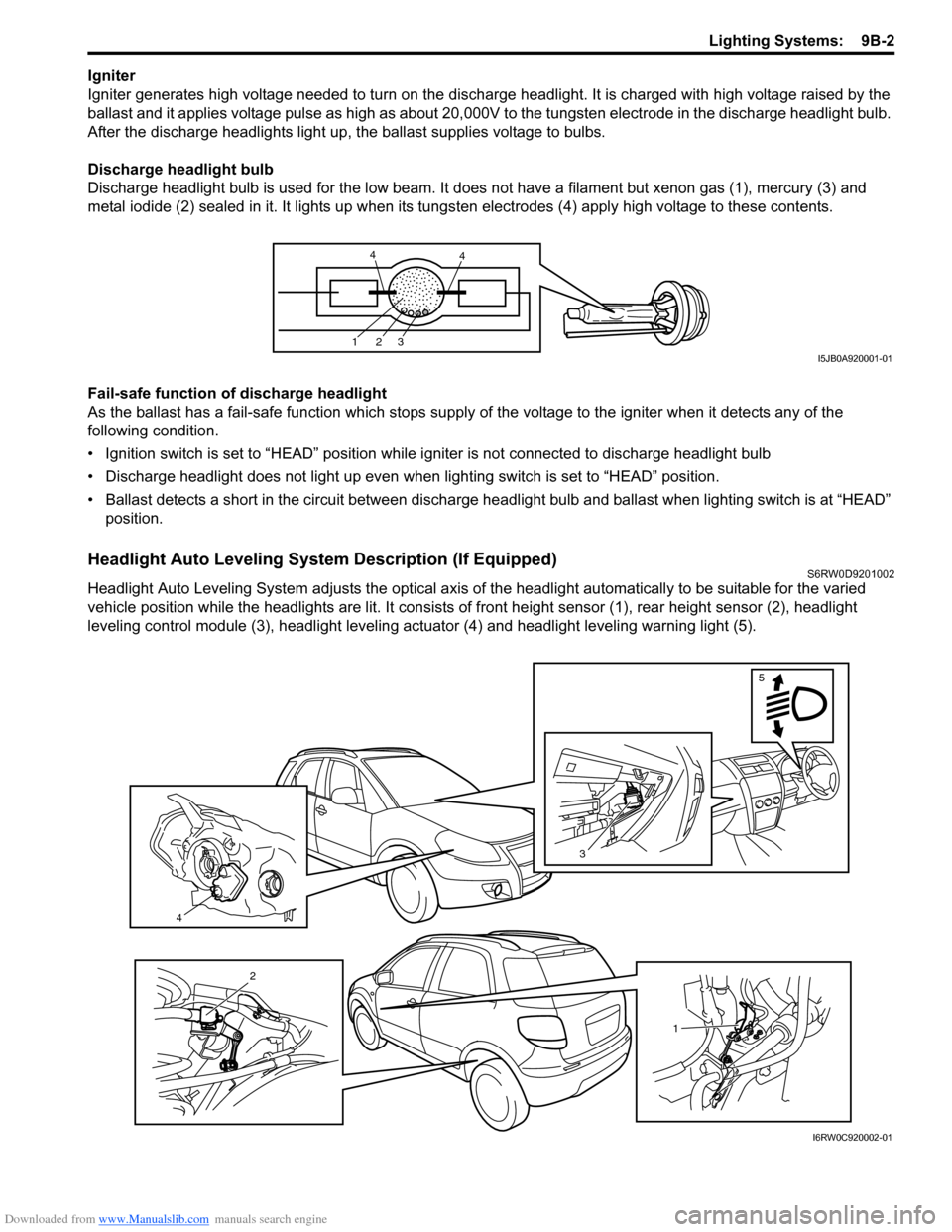
Discharge headlight bulb
Discharge headlight bulb is used for the low beam. It does not have a filament but xenon gas (1), mercury (3) and
metal iodide (2) sealed in it. It lights up when its tungsten electrodes (4) apply high voltage to these contents.
Fail-safe function of discharge headlight
As the ballast has a fail-safe function which stops supply of the voltage to the igniter when it detects any of the
following condition.
• Ignition switch is set to “HEAD” position while igniter is not connected to discharge headlight bulb
• Discharge headlight does not light up even when lighting switch is set to “HEAD” position.
• Ballast detects a short in the circuit between discharge headlight bulb and ballast when lighting switch is at “HEAD”
position.
Headlight Auto Leveling System Description (If Equipped)S6RW0D9201002
Headlight Auto Leveling System adjusts the optical axis of the headlight automatically to be suitable for the varied
vehicle position while the headlights are lit. It consists of front height sensor (1), rear height sensor (2), headlight
leveling control module (3), headlight leveling actuator (4) and headlight leveling warning light (5).
123
44
I5JB0A920001-01
4
3
5
1
2
I6RW0C920002-01
Page 1323 of 1556

Downloaded from www.Manualslib.com manuals search engine Lighting Systems: 9B-4
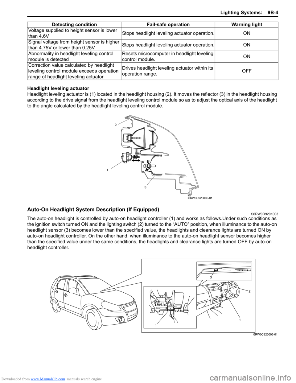
Headlight leveling actuator
Headlight leveling actuator is (1) located in the headlight housing (2). It moves the reflector (3) in the headlight housing
according to the drive signal from the headlight leveling control module so as to adjust the optical axis of the headlight
to the angle calculated by the headlight leveling control module.
Auto-On Headlight System Description (If Equipped)S6RW0D9201003
The auto-on headlight is controlled by auto-on headlight controller (1) and works as follows.Under such conditions as
the ignition switch turned ON and the lighting switch (2) turned to the “AUTO” position, when illuminance to the auto-on
headlight sensor (3) becomes lower than the specified value, the headlights and clearance lights are turned ON by
auto-on headlight controller. On the other hand, when illuminance to the auto-on headlight sensor becomes higher
than the specified value under the same conditions, the headlights and clearance lights are turned OFF by auto-on
headlight controller.Voltage supplied to height sensor is lower
than 4.6VStops headlight leveling actuator operation. ON
Signal voltage from height sensor is higher
than 4.75V or lower than 0.25VStops headlight leveling actuator operation. ON
Abnormality in headlight leveling control
module is detectedResets microcomputer in headlight leveling
control module.ON
Correction value calculated by headlight
leveling control module exceeds operation
range of headlight leveling actuatorDrives headlight leveling actuator within its
operation range.OFF Detecting condition Fail-safe operation Warning light
1
3
2
I6RW0C920005-01
1 3
2
1
I6RW0C920006-01
Page 1327 of 1556

Downloaded from www.Manualslib.com manuals search engine Lighting Systems: 9B-8
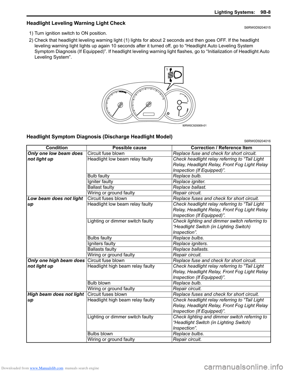
Headlight Leveling Warning Light CheckS6RW0D9204015
1) Turn ignition switch to ON position.
2) Check that headlight leveling warning light (1) lights for about 2 seconds and then goes OFF. If the headlight
leveling warning light lights up again 10 seconds after it turned off, go to “Headlight Auto Leveling System
Symptom Diagnosis (If Equipped)”. If headlight leveling warning light flashes, go to “Initialization of Headlight Auto
Leveling System”.
Headlight Symptom Diagnosis (Discharge Headlight Model)S6RW0D9204016
1
I6RW0C920009-01
Condition Possible cause Correction / Reference Item
Only one low beam does
not light upCircuit fuse blownReplace fuse and check for short circuit.
Headlight low beam relay faultyCheck headlight relay referring to “Tail Light
Relay, Headlight Relay, Front Fog Light Relay
Inspection (If Equipped)”.
Bulb faultyReplace bulb.
Igniter faultyReplace igniter.
Ballast faultyReplace ballast.
Wiring or ground faultyRepair circuit.
Low beam does not light
upCircuit fuses blownReplace fuses and check for short circuit.
Headlight low beam relay faultyCheck headlight relay referring to “Tail Light
Relay, Headlight Relay, Front Fog Light Relay
Inspection (If Equipped)”.
Lighting or dimmer switch faultyCheck lighting and dimmer switch referring to
“Headlight Switch (in Lighting Switch)
Inspection”.
Bulbs faultyReplace bulbs.
Igniters faultyReplace igniters.
Ballasts faultyReplace ballasts.
Wiring or ground faultyRepair circuit.
Only one high beam does
not light upCircuit fuse blownReplace fuse and check for short circuit.
Headlight high beam relay faultyCheck headlight relay referring to “Tail Light
Relay, Headlight Relay, Front Fog Light Relay
Inspection (If Equipped)”.
Bulb blownReplace bulb.
Wiring or ground faultyRepair circuit.
High beam does not light
upCircuit fuses blownReplace fuses and check for short circuit.
Headlight high beam relay faultyCheck headlight relay referring to “Tail Light
Relay, Headlight Relay, Front Fog Light Relay
Inspection (If Equipped)”.
Lighting or dimmer switch faultyCheck lighting and dimmer switch referring to
“Headlight Switch (in Lighting Switch)
Inspection”.
Bulbs blownReplace bulbs.
Wiring or ground faultyRepair circuit.