2006 SUZUKI SX4 warning lights
[x] Cancel search: warning lightsPage 1329 of 1556
Downloaded from www.Manualslib.com manuals search engine Lighting Systems: 9B-10
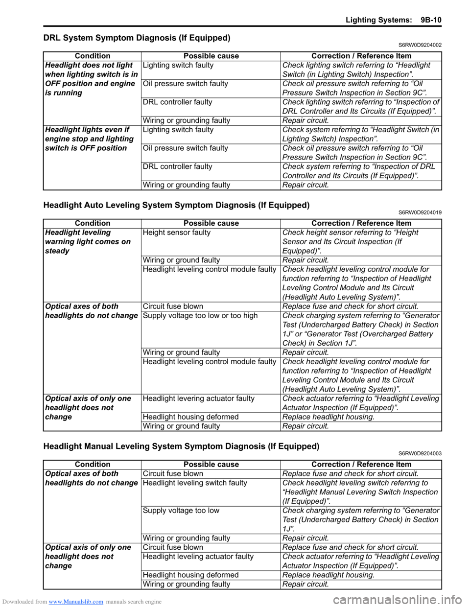
DRL System Symptom Diagnosis (If Equipped)S6RW0D9204002
Headlight Auto Leveling System Symptom Diagnosis (If Equipped)S6RW0D9204019
Headlight Manual Leveling System Symptom Diagnosis (If Equipped)S6RW0D9204003
Condition Possible cause Correction / Reference Item
Headlight does not light
when lighting switch is in
OFF position and engine
is runningLighting switch faultyCheck lighting switch referring to “Headlight
Switch (in Lighting Switch) Inspection”.
Oil pressure switch faultyCheck oil pressure switch referring to “Oil
Pressure Switch Inspection in Section 9C”.
DRL controller faultyCheck lighting switch referring to “Inspection of
DRL Controller and Its Circuits (If Equipped)”.
Wiring or grounding faultyRepair circuit.
Headlight lights even if
engine stop and lighting
switch is OFF positionLighting switch faultyCheck system referring to “Headlight Switch (in
Lighting Switch) Inspection”.
Oil pressure switch faultyCheck oil pressure switch referring to “Oil
Pressure Switch Inspection in Section 9C”.
DRL controller faultyCheck system referring to “Inspection of DRL
Controller and Its Circuits (If Equipped)”.
Wiring or grounding faultyRepair circuit.
Condition Possible cause Correction / Reference Item
Headlight leveling
warning light comes on
steadyHeight sensor faultyCheck height sensor referring to “Height
Sensor and Its Circuit Inspection (If
Equipped)”.
Wiring or ground faultyRepair circuit.
Headlight leveling control module faultyCheck headlight leveling control module for
function referring to “Inspection of Headlight
Leveling Control Module and Its Circuit
(Headlight Auto Leveling System)”.
Optical axes of both
headlights do not changeCircuit fuse blownReplace fuse and check for short circuit.
Supply voltage too low or too highCheck charging system referring to “Generator
Test (Undercharged Battery Check) in Section
1J” or “Generator Test (Overcharged Battery
Check) in Section 1J”.
Wiring or ground faultyRepair circuit.
Headlight leveling control module faultyCheck headlight leveling control module for
function referring to “Inspection of Headlight
Leveling Control Module and Its Circuit
(Headlight Auto Leveling System)”.
Optical axis of only one
headlight does not
changeHeadlight levering actuator faultyCheck actuator referring to “Headlight Leveling
Actuator Inspection (If Equipped)”.
Headlight housing deformedReplace headlight housing.
Wiring or ground faultyRepair circuit.
Condition Possible cause Correction / Reference Item
Optical axes of both
headlights do not changeCircuit fuse blownReplace fuse and check for short circuit.
Headlight leveling switch faultyCheck headlight leveling switch referring to
“Headlight Manual Levering Switch Inspection
(If Equipped)”.
Supply voltage too lowCheck charging system referring to “Generator
Test (Undercharged Battery Check) in Section
1J”.
Wiring or grounding faultyRepair circuit.
Optical axis of only one
headlight does not
changeCircuit fuse blownReplace fuse and check for short circuit.
Headlight leveling actuator faultyCheck actuator referring to “Headlight Leveling
Actuator Inspection (If Equipped)”.
Headlight housing deformedReplace headlight housing.
Wiring or grounding faultyRepair circuit.
Page 1330 of 1556
Downloaded from www.Manualslib.com manuals search engine 9B-11 Lighting Systems:
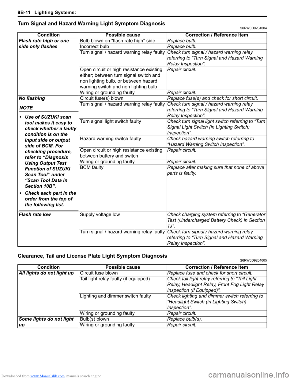
Turn Signal and Hazard Warning Light Symptom DiagnosisS6RW0D9204004
Clearance, Tail and License Plate Light Symptom DiagnosisS6RW0D9204005
Condition Possible cause Correction / Reference Item
Flash rate high or one
side only flashesBulb blown on “flash rate high”-sideReplace bulb.
Incorrect bulbReplace bulb.
Turn signal / hazard warning relay faultyCheck turn signal / hazard warning relay
referring to “Turn Signal and Hazard Warning
Relay Inspection”.
Open circuit or high resistance existing
either; between turn signal switch and
non lighting bulb, or between hazard
warning switch and non lighting bulbRepair circuit.
Wiring or grounding faultyRepair circuit.
No flashing
NOTE
• Use of SUZUKI scan
tool makes it easy to
check whether a faulty
condition is on the
input side or output
side of BCM. For
checking procedure,
refer to “Diagnosis
Using Output Test
Function of SUZUKI
Scan Tool” under
“Scan Tool Data in
Section 10B”.
• Check each part in the
order from the top of
the following list.
Circuit fuse(s) blownReplace fuse(s) and check for short circuit.
Turn signal / hazard warning relay faultyCheck turn signal / hazard warning relay
referring to “Turn Signal and Hazard Warning
Relay Inspection”.
Turn signal light switch faultyCheck turn signal light switch referring to “Turn
Signal Light Switch (in Lighting Switch)
Inspection”.
Hazard warning switch faultyCheck hazard warning switch referring to
“Hazard Warning Switch Inspection”.
Open circuit or high resistance existing
between battery and switchRepair circuit.
Wiring or grounding faultyRepair circuit.
BCM faultyReplace after making sure that none of above
parts is faulty.
Flash rate lowSupply voltage lowCheck charging system referring to “Generator
Test (Undercharged Battery Check) in Section
1J”.
Turn signal / hazard warning relay faultyCheck turn signal / hazard warning relay
referring to “Turn Signal and Hazard Warning
Relay Inspection”.
Condition Possible cause Correction / Reference Item
All lights do not light upCircuit fuse blownReplace fuse and check for short circuit.
Tail light relay faulty (if equipped)Check tail light relay referring to “Tail Light
Relay, Headlight Relay, Front Fog Light Relay
Inspection (If Equipped)”.
Lighting and dimmer switch faultyCheck lighting and dimmer switch referring to
“Headlight Switch (in Lighting Switch)
Inspection”.
Wiring or grounding faultyRepair circuit.
Some lights do not light
upBulb(s) blownReplace bulb(s).
Wiring or grounding faultyRepair circuit.
Page 1339 of 1556
Downloaded from www.Manualslib.com manuals search engine Lighting Systems: 9B-20
Igniter Removal and Installation (Discharge
Headlight Model)
S6RW0D9206024
WARNING!
Be sure to read “Precautions for Discharge
Headlight Service (If Equipped)” carefully
before working. Neglecting them may result
in personal injury.
Removal
1) Remove ballast referring to “Ballast Removal and
Installation (Discharge Headlight Model)”.
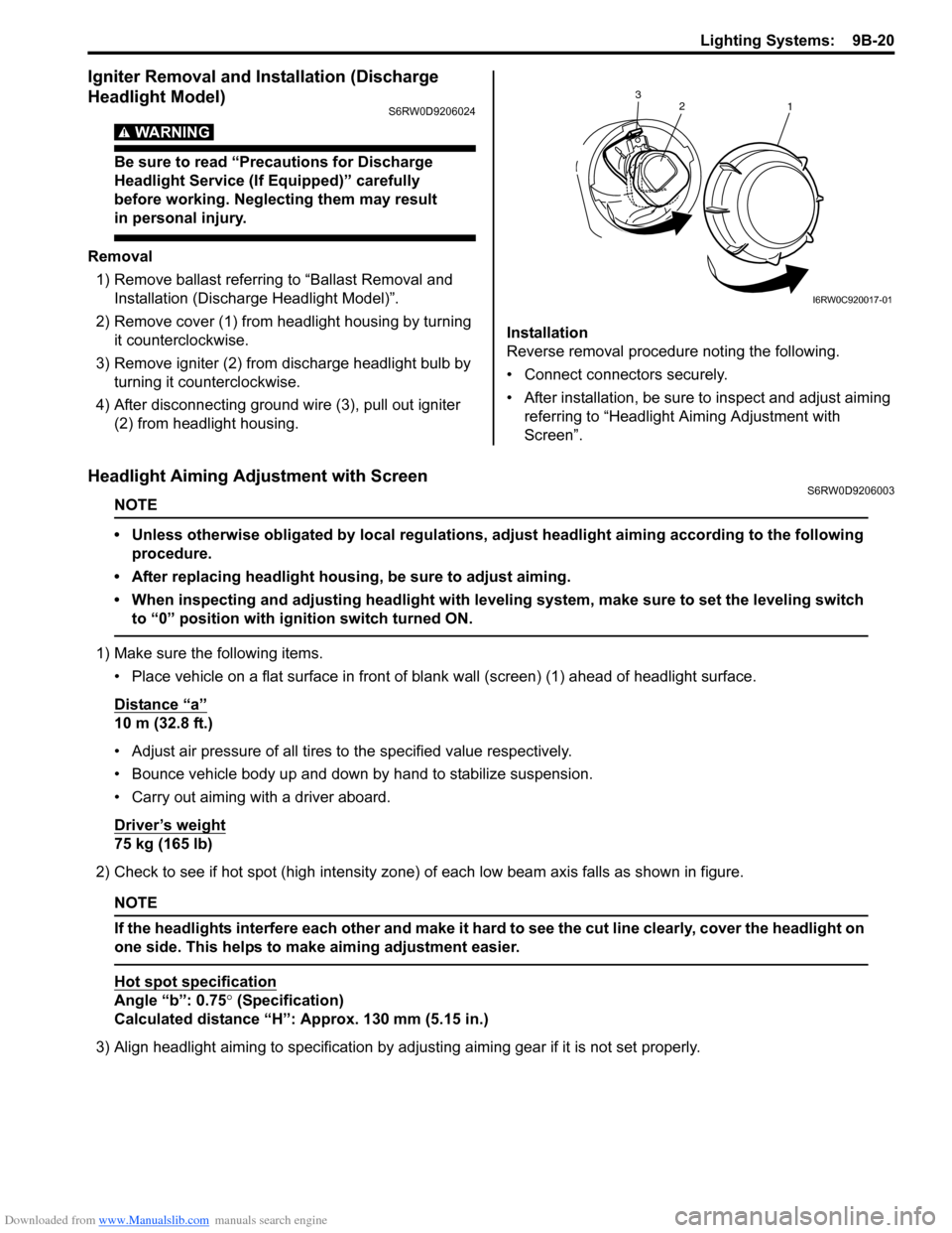
2) Remove cover (1) from headlight housing by turning
it counterclockwise.
3) Remove igniter (2) from discharge headlight bulb by
turning it counterclockwise.
4) After disconnecting ground wire (3), pull out igniter
(2) from headlight housing.Installation
Reverse removal procedure noting the following.
• Connect connectors securely.
• After installation, be sure to inspect and adjust aiming
referring to “Headlight Aiming Adjustment with
Screen”.
Headlight Aiming Adjustment with ScreenS6RW0D9206003
NOTE
• Unless otherwise obligated by local regulations, adjust headlight aiming according to the following
procedure.
• After replacing headlight housing, be sure to adjust aiming.
• When inspecting and adjusting headlight with leveling system, make sure to set the leveling switch
to “0” position with ignition switch turned ON.
1) Make sure the following items.
• Place vehicle on a flat surface in front of blank wall (screen) (1) ahead of headlight surface.
Distance “a”
10 m (32.8 ft.)
• Adjust air pressure of all tires to the specified value respectively.
• Bounce vehicle body up and down by hand to stabilize suspension.
• Carry out aiming with a driver aboard.
Driver’s weight
75 kg (165 lb)
2) Check to see if hot spot (high intensity zone) of each low beam axis falls as shown in figure.
NOTE
If the headlights interfere each other and make it hard to see the cut line clearly, cover the headlight on
one side. This helps to make aiming adjustment easier.
Hot spot specification
Angle “b”: 0.75° (Specification)
Calculated distance “H”: Approx. 130 mm (5.15 in.)
3) Align headlight aiming to specification by adjusting aiming gear if it is not set properly.
2
1 3
I6RW0C920017-01
Page 1345 of 1556
Downloaded from www.Manualslib.com manuals search engine Lighting Systems: 9B-26
Front Fog Light Assembly Removal and
Installation (If Equipped)
S6RW0D9206014
WARNING!
• To avoid danger of being burned, don’t
touch when the bulb is hot.
• Don’t touch glass surface of bulb to avoid
deteriorate as the case may be unclear
when bulb light on at dirty condition.
Removal
1) Disconnect negative (–) cable at battery.
2) Remove front bumper. Refer to “Front Bumper and
Rear Bumper Components in Section 9K”.
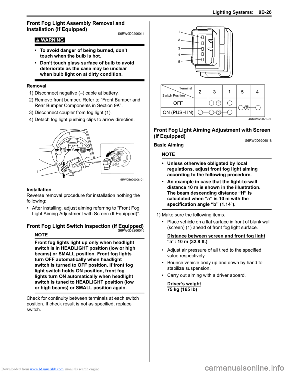
3) Disconnect coupler from fog light (1).
4) Detach fog light pushing clips to arrow direction.
Installation
Reverse removal procedure for installation nothing the
following:
• After installing, adjust aiming referring to “Front Fog
Light Aiming Adjustment with Screen (If Equipped)”.
Front Fog Light Switch Inspection (If Equipped)S6RW0D9206016
NOTE
Front fog lights light up only when headlight
switch is in HEADLIGHT position (low or high
beams) or SMALL position. Front fog lights
turn OFF automatically when headlight
switch is turned to OFF position. If front fog
light switch holds ON position, front fog
lights turn ON automatically when headlight
switch is tuned to HEADLIGHT position (low
or high beams) or SMALL position again.
Check for continuity between terminals at each switch
position. If check result is not as specified, replace
switch.
Front Fog Light Aiming Adjustment with Screen
(If Equipped)
S6RW0D9206018
Basic Aiming
NOTE
• Unless otherwise obligated by local
regulations, adjust front fog light aiming
according to the following procedure.
• An example in case that the light-to-wall
distance 10 m is shown in the illustration.
The beam descending distance “H” is
calculated when “a” is 10 m with the
specification angle “b” (1.14°).
1) Make sure the following items.
• Place vehicle on a flat surface in front of blank wall
(screen) (1) ahead of front fog light surface.
Distance between screen and front fog light
“a”: 10 m (32.8 ft.)
• Adjust air pressure of all tired to the specified
value respectively.
• Bounce vehicle body up and down by hand to
stabilize suspension.
• Carry out aiming with a driver aboard.
Driver’s weight
75 kg (165 lb)
1
I6RW0B920006-01
1
2
3
4
5
Switch PositionTerminal
ON (PUSH IN)231
54
OFF
I4RS0A920021-01
Page 1347 of 1556
Downloaded from www.Manualslib.com manuals search engine Lighting Systems: 9B-28
Headlight Manual Levering Switch Inspection (If
Equipped)
S6RW0D9206019
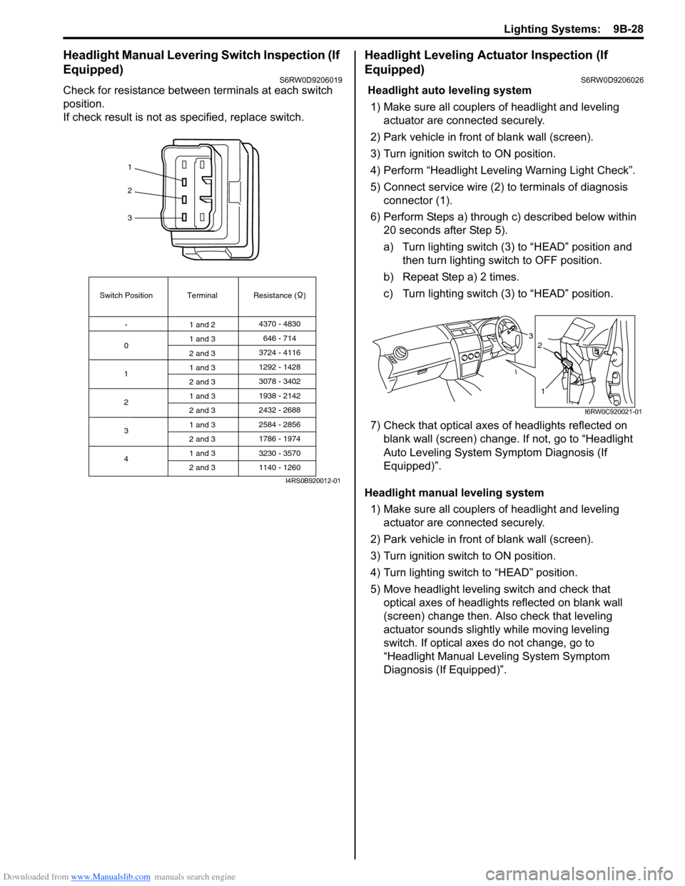
Check for resistance between terminals at each switch
position.
If check result is not as specified, replace switch.
Headlight Leveling Actuator Inspection (If
Equipped)
S6RW0D9206026
Headlight auto leveling system
1) Make sure all couplers of headlight and leveling
actuator are connected securely.
2) Park vehicle in front of blank wall (screen).
3) Turn ignition switch to ON position.
4) Perform “Headlight Leveling Warning Light Check”.
5) Connect service wire (2) to terminals of diagnosis
connector (1).
6) Perform Steps a) through c) described below within
20 seconds after Step 5).
a) Turn lighting switch (3) to “HEAD” position and
then turn lighting switch to OFF position.
b) Repeat Step a) 2 times.
c) Turn lighting switch (3) to “HEAD” position.
7) Check that optical axes of headlights reflected on
blank wall (screen) change. If not, go to “Headlight
Auto Leveling System Symptom Diagnosis (If
Equipped)”.
Headlight manual leveling system
1) Make sure all couplers of headlight and leveling
actuator are connected securely.
2) Park vehicle in front of blank wall (screen).
3) Turn ignition switch to ON position.
4) Turn lighting switch to “HEAD” position.
5) Move headlight leveling switch and check that
optical axes of headlights reflected on blank wall
(screen) change then. Also check that leveling
actuator sounds slightly while moving leveling
switch. If optical axes do not change, go to
“Headlight Manual Leveling System Symptom
Diagnosis (If Equipped)”.
1
2
3
Switch Position
0Terminal Resistance ( )
-
1
2
3
41 and 24370 - 4830
1 and 3
2 and 3
1 and 3
2 and 3
1 and 3
2 and 3
1 and 3
2 and 3
1 and 3
2 and 3646 - 714
3724 - 4116
3078 - 3402 1292 - 1428
1938 - 2142
2584 - 2856
3230 - 3570 2432 - 2688
1786 - 1974
1140 - 1260
I4RS0B920012-01
3
1
2
I6RW0C920021-01
Page 1415 of 1556
Downloaded from www.Manualslib.com manuals search engine Security and Locks: 9F-4
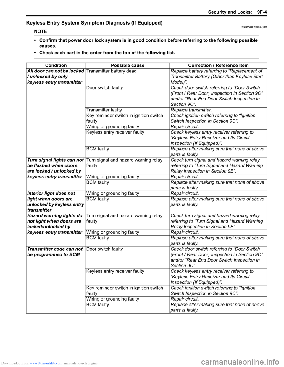
Keyless Entry System Symptom Diagnosis (If Equipped)S6RW0D9604003
NOTE
• Confirm that power door lock system is in good condition before referring to the following possible
causes.
• Check each part in the order from the top of the following list.
Condition Possible cause Correction / Reference Item
All door can not be locked
/ unlocked by only
keyless entry transmitterTransmitter battery deadReplace battery referring to “Replacement of
Transmitter Battery (Other than Keyless Start
Model)”.
Door switch faultyCheck door switch referring to “Door Switch
(Front / Rear Door) Inspection in Section 9C”
and/or “Rear End Door Switch Inspection in
Section 9C”.
Transmitter faultyReplace transmitter.
Key reminder switch in ignition switch
faultyCheck ignition switch referring to “Ignition
Switch Inspection in Section 9C”.
Wiring or grounding faultyRepair circuit.
Keyless entry receiver faultyCheck keyless entry receiver referring to
“Keyless Entry Receiver and Its Circuit
Inspection (If Equipped)”.
BCM faultyReplace after making sure that none of above
parts is faulty.
Turn signal lights can not
be flashed when doors
are locked / unlocked by
keyless entry transmitterTurn signal and hazard warning relay
faultyCheck turn signal and hazard warning relay
referring to “Turn Signal and Hazard Warning
Relay Inspection in Section 9B”.
Wiring or grounding faultyRepair circuit.
BCM faultyReplace after making sure that none of above
parts is faulty.
Interior light does not
light when doors are
unlocked by keyless entry
transmitterWiring or grounding faultyRepair circuit.
BCM faultyReplace after making sure that none of above
parts is faulty.
Hazard warning lights do
not light when doors are
locked/unlocked by
keyless entry transmitterTurn signal and hazard warning relay
faultyCheck turn signal and hazard warning relay
referring to “Turn Signal and Hazard Warning
Relay Inspection in Section 9B”.
Wiring or grounding faultyRepair circuit.
BCM faultyReplace after making sure that none of above
parts is faulty.
Transmitter code can not
be programmed to BCMDoor switch faultyCheck door switch referring to “Door Switch
(Front / Rear Door) Inspection in Section 9C”
and/or “Rear End Door Switch Inspection in
Section 9C”.
Keyless entry receiver faultyCheck keyless entry receiver referring to
“Keyless Entry Receiver and Its Circuit
Inspection (If Equipped)”.
Key reminder switch in ignition switch
faultyCheck ignition switch referring to “Ignition
Switch Inspection in Section 9C”.
Wiring or grounding faultyRepair circuit.
BCM faultyReplace after making sure that none of above
parts is faulty.
Page 1425 of 1556
Downloaded from www.Manualslib.com manuals search engine Security and Locks: 9F-14
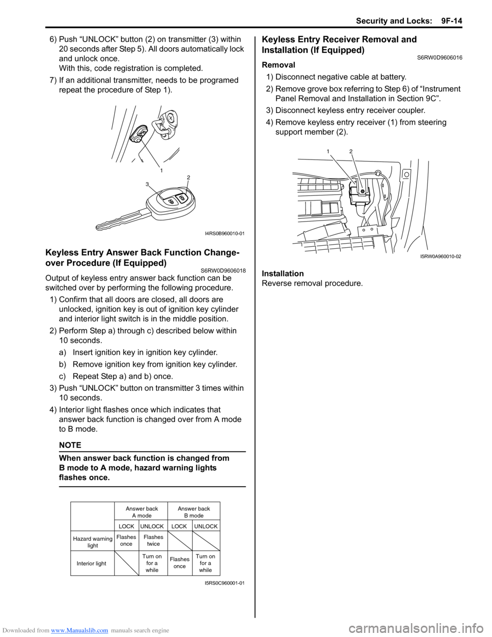
6) Push “UNLOCK” button (2) on transmitter (3) within
20 seconds after Step 5). All doors automatically lock
and unlock once.
With this, code registration is completed.
7) If an additional transmitter, needs to be programed
repeat the procedure of Step 1).
Keyless Entry Answer Back Function Change-
over Procedure (If Equipped)
S6RW0D9606018
Output of keyless entry answer back function can be
switched over by performing the following procedure.
1) Confirm that all doors are closed, all doors are
unlocked, ignition key is out of ignition key cylinder
and interior light switch is in the middle position.
2) Perform Step a) through c) described below within
10 seconds.
a) Insert ignition key in ignition key cylinder.
b) Remove ignition key from ignition key cylinder.
c) Repeat Step a) and b) once.
3) Push “UNLOCK” button on transmitter 3 times within
10 seconds.
4) Interior light flashes once which indicates that
answer back function is changed over from A mode
to B mode.
NOTE
When answer back function is changed from
B mode to A mode, hazard warning lights
flashes once.
Keyless Entry Receiver Removal and
Installation (If Equipped)
S6RW0D9606016
Removal
1) Disconnect negative cable at battery.
2) Remove grove box referring to Step 6) of “Instrument
Panel Removal and Installation in Section 9C”.
3) Disconnect keyless entry receiver coupler.
4) Remove keyless entry receiver (1) from steering
support member (2).
Installation
Reverse removal procedure.
1
32
I4RS0B960010-01
Hazard warning
light
LOCK LOCKUNLOCK UNLOCK
Interior lightFlashes
onceFlashes
twice
Flashes
once Turn on
for a
whileTurn on
for a
while Answer back
A modeAnswer back
B mode
I5RS0C960001-01
12
I5RW0A960010-02
Page 1434 of 1556
Downloaded from www.Manualslib.com manuals search engine 9H-2 Interior Trim:
Head Lining Removal and InstallationS6RW0D9806002
WARNING!
Refer to “Air Bag System Service Warning in
Section 00” before starting service work.
Removal
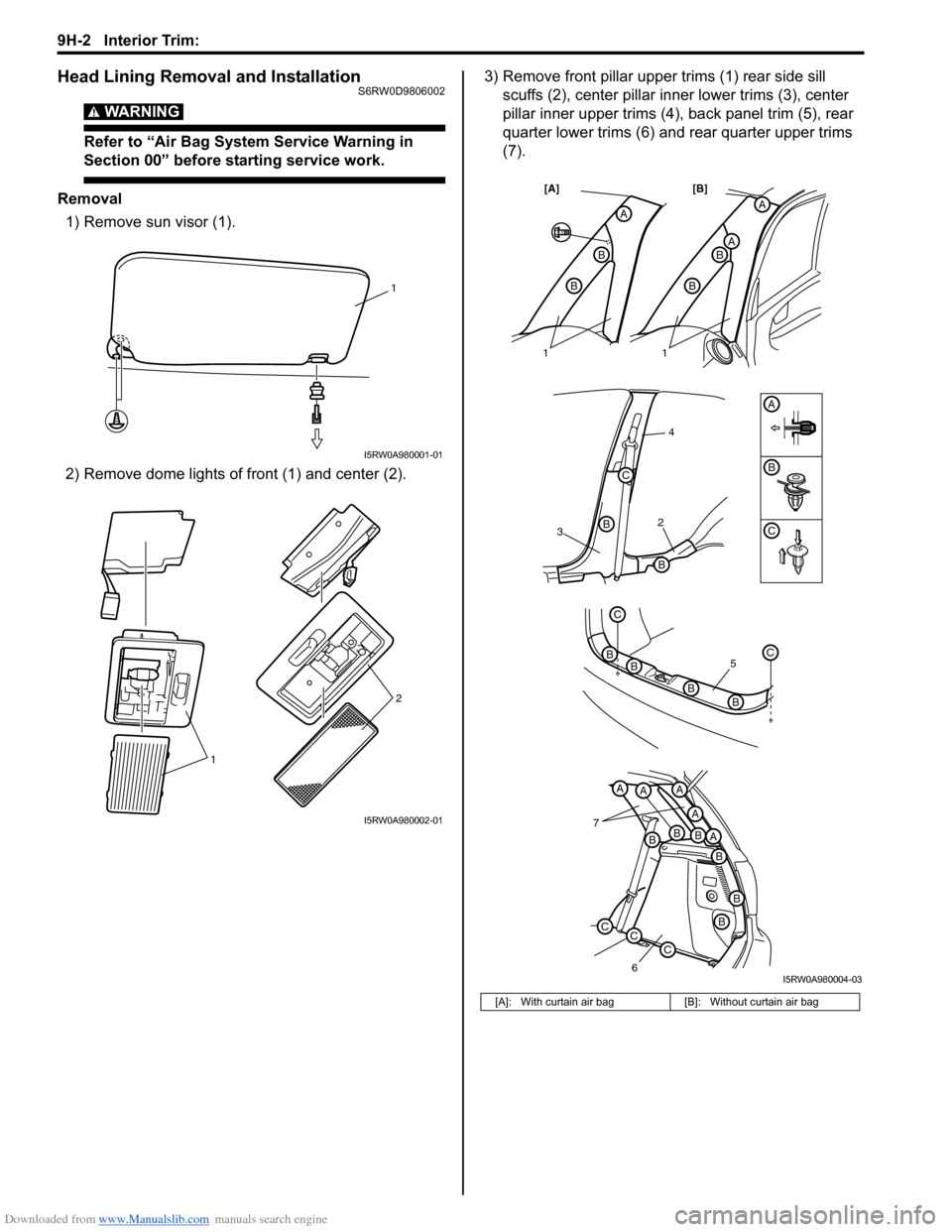
1) Remove sun visor (1).
2) Remove dome lights of front (1) and center (2).3) Remove front pillar upper trims (1) rear side sill
scuffs (2), center pillar inner lower trims (3), center
pillar inner upper trims (4), back panel trim (5), rear
quarter lower trims (6) and rear quarter upper trims
(7).
1
I5RW0A980001-01
12
I5RW0A980002-01
[A]: With curtain air bag [B]: Without curtain air bag
32
4
B
B
B
C
A
A
AB
B
A
B
B
[A] [B]
7
6
BBBA
A
AAA
B
B
B
CCC
5
C
BC
BB
B
11
C
I5RW0A980004-03