Page 404 of 1556

Downloaded from www.Manualslib.com manuals search engine 1H-9 Ignition System:
2) Start engine and warm it up to normal operating
temperature.
3) Make sure that all of electrical loads except ignition
are switched off.
4) Check to be sure that idle speed is within
specification.
5) Fix ignition timing by using “Fixed Spark Control” of
“Engine / Active Test” mode on scan tool.
6) Set timing light (1) to high-tension cord for No.1
cylinder and check that ignition timing is within
specification.
Initial ignition timing
fixed with SUZUKI scan tool: 5 ± 3° BTDC (at
specified idle speed)
Ignition order
1 – 3 – 4 – 2
Special tool
(A): 09930–764207) If ignition timing is out of specification, check the
followings.
• CKP sensor
• CKP sensor plate
• TP sensor
• CMP sensor
• CMP sensor rotor tooth of camshaft
• Vehicle speed signal from ABS hydraulic unit /
control module
• Knock sensor
• Timing chain cover installation
8) After checking initial ignition timing, release ignition
timing fixation by using scan tool.
9) With engine idling (throttle opening at closed position
and vehicle stopped), check that ignition timing is
about 5° – 15° BTDC (Constant variation within a
few degrees from 5° – 15° BTDC indicates no
abnormality but proves operation of electronic timing
control system.) Also, check that increasing engine
speed advances ignition timing.
If the check results are not satisfactory, check CKP
sensor and ECM.
1, (A)10
0I3RB0A180004-01
Page 1178 of 1556
Downloaded from www.Manualslib.com manuals search engine 9A-11 Wiring Systems:
Connector Layout Diagram
Connector Layout DiagramS6RW0D910A001
Refer to “Engine Compartment”.
Refer to “Instrument Panel”.
Refer to “Door, Roof”.
Refer to “Floor”.
Refer to “Rear”.
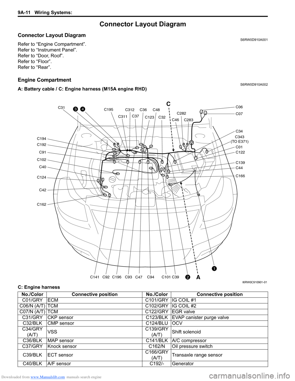
Engine CompartmentS6RW0D910A002
A: Battery cable / C: Engine harness (M15A engine RHD)
C: Engine harness
C124
C40
C102
C91
C192
C194
C42
C162
C141C196
C195
C93C94C101C39C92
C31
C311C312
C36C48
C37C123
C47C32C282
C283
C343
(TO E371)
C01
C34
C07
C06
C122
C46
C139
C44
C166
43
2
1
C
A
I6RW0C910901-01
No./Color Connective position No./Color Connective position
C01/GRY ECM C101/GRY IG COIL #1
C06/N (A/T) TCM C102/GRY IG COIL #2
C07/N (A/T) TCM C122/GRY EGR valve
C31/GRY CKP sensor C123/BLK EVAP canister purge valve
C32/BLK CMP sensor C124/BLU OCV
C34/GRY
(A/T)VSSC139/GRY
(A/T)Shift solenoid
C36/BLK MAP sensor C141/BLK A/C compressor
C37/GRY Knock sensor C162/N Oil pressure switch
C39/BLK ECT sensorC166/GRY
(A/T)Transaxle range sensor
C40/BLK A/F sensor C192/- Generator
Page 1180 of 1556
Downloaded from www.Manualslib.com manuals search engine 9A-13 Wiring Systems:
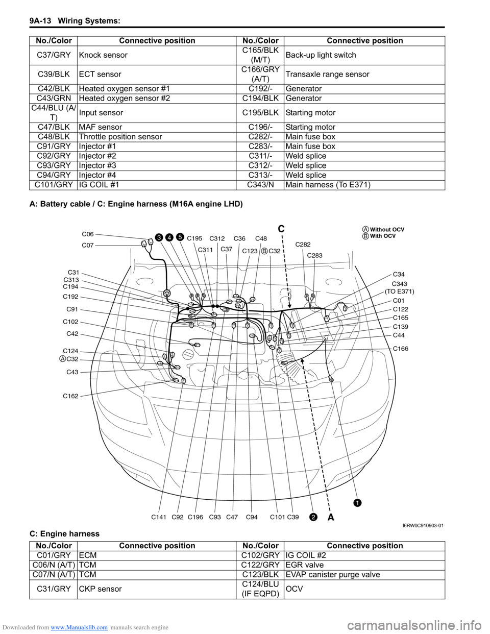
A: Battery cable / C: Engine harness (M16A engine LHD)
C: Engine harnessC37/GRY Knock sensorC165/BLK
(M/T)Back-up light switch
C39/BLK ECT sensorC166/GRY
(A/T)Transaxle range sensor
C42/BLK Heated oxygen sensor #1 C192/- Generator
C43/GRN Heated oxygen sensor #2 C194/BLK Generator
C44/BLU (A/
T)Input sensor C195/BLK Starting motor
C47/BLK MAF sensor C196/- Starting motor
C48/BLK Throttle position sensor C282/- Main fuse box
C91/GRY Injector #1 C283/- Main fuse box
C92/GRY Injector #2 C311/- Weld splice
C93/GRY Injector #3 C312/- Weld splice
C94/GRY Injector #4 C313/- Weld splice
C101/GRY IG COIL #1 C343/N Main harness (To E371)No./Color Connective position No./Color Connective position
C124
C32
C42
C102
C91
C192
C194
C43
C162
C141C196
C195
C93C94C101C39C92
C31
C311
C313C312
C36C48
C37C123
C47C32C282
C283
C343
(TO E371)
C01
C34
C07
C06
C122
C165
C139
C44
C166
43
2
1
5C
AWithout OCV
With OCV A
A
B
B
I6RW0C910903-01
No./Color Connective position No./Color Connective position
C01/GRY ECM C102/GRY IG COIL #2
C06/N (A/T) TCM C122/GRY EGR valve
C07/N (A/T) TCM C123/BLK EVAP canister purge valve
C31/GRY CKP sensorC124/BLU
(IF EQPD)OCV
Page 1181 of 1556
Downloaded from www.Manualslib.com manuals search engine Wiring Systems: 9A-14
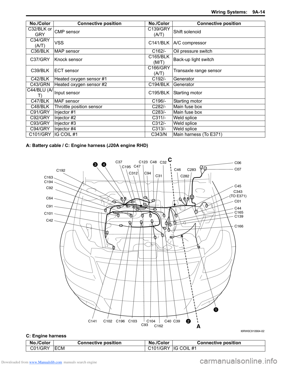
A: Battery cable / C: Engine harness (J20A engine RHD)
C: Engine harnessC32/BLK or
GRYCMP sensorC139/GRY
(A/T)Shift solenoid
C34/GRY
(A/T)VSS C141/BLK A/C compressor
C36/BLK MAP sensor C162/- Oil pressure switch
C37/GRY Knock sensorC165/BLK
(M/T)Back-up light switch
C39/BLK ECT sensorC166/GRY
(A/T)Transaxle range sensor
C42/BLK Heated oxygen sensor #1 C192/- Generator
C43/GRN Heated oxygen sensor #2 C194/BLK Generator
C44/BLU (A/
T)Input sensor C195/BLK Starting motor
C47/BLK MAF sensor C196/- Starting motor
C48/BLK Throttle position sensor C282/- Main fuse box
C91/GRY Injector #1 C283/- Main fuse box
C92/GRY Injector #2 C311/- Weld splice
C93/GRY Injector #3 C312/- Weld splice
C94/GRY Injector #4 C313/- Weld splice
C101/GRY IG COIL #1 C343/N Main harness (To E371)No./Color Connective position No./Color Connective position
C42
C101
C91
C64 C92
C194 C163
C141C102C196 C192
C195
C312
C93C104C103
C94C31C32
C40
C162
C39
C123C48C37
C47
C282
C283C46
C343
(TO E371)
C01
C45
C07
C06
C139 C44
C165
C166
3
2
1
4
A
C
I6RW0C910904-02
No./Color Connective position No./Color Connective position
C01/GRY ECM C101/GRY IG COIL #1
Page 1182 of 1556
Downloaded from www.Manualslib.com manuals search engine 9A-15 Wiring Systems:
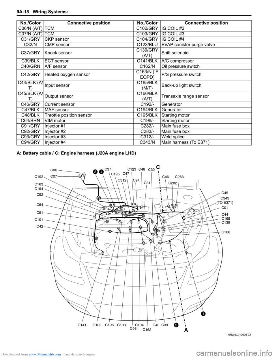
A: Battery cable / C: Engine harness (J20A engine LHD)C06/N (A/T) TCM C102/GRY IG COIL #2
C07/N (A/T) TCM C103/GRY IG COIL #3
C31/GRY CKP sensor C104/GRY IG COIL #4
C32/N CMP sensor C123/BLU EVAP canister purge valve
C37/GRY Knock sensorC139/GRY
(A/T)Shift solenoid
C39/BLK ECT sensor C141/BLK A/C compressor
C40/GRN A/F sensor C162/N Oil pressure switch
C42/GRY Heated oxygen sensorC163/N (IF
EQPD)P/S pressure switch
C44/BLK (A/
T)Input sensorC165/BLK
(M/T)Back-up light switch
C45/BLK (A/
T)Output sensorC166/BLK
(A/T)Transaxle range sensor
C46/GRY Current sensor C192/- Generator
C47/BLK MAF sensor C194/BLK Generator
C48/BLK Throttle position sensor C195/BLK Starting motor
C64/BRN VIM motor C196/- Starting motor
C91/GRY Injector #1 C282/- Main fuse box
C92/GRY Injector #2 C283/- Main fuse box
C93/GRY Injector #3 C312/- Weld splice
C94/GRY Injector #4 C343/N Main harness (To E371) No./Color Connective position No./Color Connective position
C42
C101
C91
C64 C92
C194 C163
C141C102C196 C192
C195
C312
C93C104C103
C94C31C32
C40
C162
C39
C123C48C37
C47
C282
C283C46
C343
(TO E371)
C01
C45
C07
C06
C139 C44
C165
C166
3
2
1
4C
A
I6RW0C910905-02
Page 1183 of 1556
Downloaded from www.Manualslib.com manuals search engine Wiring Systems: 9A-16
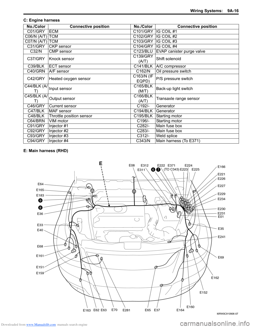
C: Engine harness
E: Main harness (RHD)No./Color Connective position No./Color Connective position
C01/GRY ECM C101/GRY IG COIL #1
C06/N (A/T) TCM C102/GRY IG COIL #2
C07/N (A/T) TCM C103/GRY IG COIL #3
C31/GRY CKP sensor C104/GRY IG COIL #4
C32/N CMP sensor C123/BLU EVAP canister purge valve
C37/GRY Knock sensorC139/GRY
(A/T)Shift solenoid
C39/BLK ECT sensor C141/BLK A/C compressor
C40/GRN A/F sensor C162/N Oil pressure switch
C42/GRY Heated oxygen sensorC163/N (IF
EQPD)P/S pressure switch
C44/BLK (A/
T)Input sensorC165/BLK
(M/T)Back-up light switch
C45/BLK (A/
T)Output sensorC166/BLK
(A/T)Transaxle range sensor
C46/GRY Current sensor C192/- Generator
C47/BLK MAF sensor C194/BLK Generator
C48/BLK Throttle position sensor C195/BLK Starting motor
C64/BRN VIM motor C196/- Starting motor
C91/GRY Injector #1 C282/- Main fuse box
C92/GRY Injector #2 C283/- Main fuse box
C93/GRY Injector #3 C312/- Weld splice
C94/GRY Injector #4 C343/N Main harness (To E371)
E68
E40
E33
E165
E36
E161
E151
E159
E70E281E163E62E63E65E37E164
E64
E183
E08
E311
E312E222E224E225E223
E221
E371
(TO C343)E166
E227
E229
E234
E230
E01
E35
E241
E69
E162
E152
E160
E231
E226
8
9
76
E
I6RW0C910906-07
Page 1231 of 1556
Downloaded from www.Manualslib.com manuals search engine Wiring Systems: 9A-64
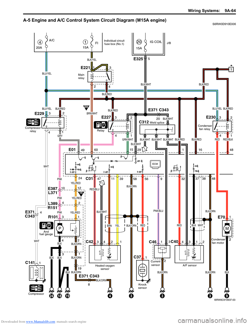
A-5 Engine and A/C Control System Circuit Diagram (M15A engine)S6RW0D910E006
YEL/RED
E387
L3711012
L389
R15142
PNKYEL/RED
P
PNKYEL/RED
31
433
31
E371 C343
BLK/ORN
BLK/ORN
BLK/ORN
BLK/ORN
19
8
BLK42
R101
1
And
fuel gauge
Main
relay
1
BLK/WHT
BLK/REDBLU/YEL
C312Weld splice
GRN/WHTBLK/WHT
BLK/WHT
BLK/WHT
IG COILJ/B1
15A
FI
BLK/YEL
E2211
23
415A
20
BRN/WHT
BW
YR
4
20A
A/C
Compressor
relay
E229
Relay
BLU/YEL
BLU/YEL
Compressor
C1411
E3255
E371 C343
20
E371
C3434BLK/WHT
C42C40
Heated oxygen
sensor
RED/BLU
BRN
A/F sensorCondenser
fan motor Condenser
fan relay
BLK
BLK/ORN
BLK/ORN
RED
C01
1
34 2 143 12
4711393237
WHT
3848PNK
ECM
142
3
WHT
WHT
BLK/RED
BLK/REDBLK/WHT
BLK/RED
BLK/RED
BLK/RED
E01496015291
GRY
E22732
4
1
E23032
4
1
YELBLK/ORN
24
BLKBLK
58 56
BLK/REDRED
16 48
182419
Individual circuit
fuse box (No.1)
BLKBLKBLK/ORNBLK/ORN
93
RED/BLK
M
1
2E70
9
PNK/BLU
RED
Knock
sensor
C371
BLK/WHT
Current
sensor
C461
23
I6RW0C910937-03
Page 1235 of 1556
Downloaded from www.Manualslib.com manuals search engine Wiring Systems: 9A-68
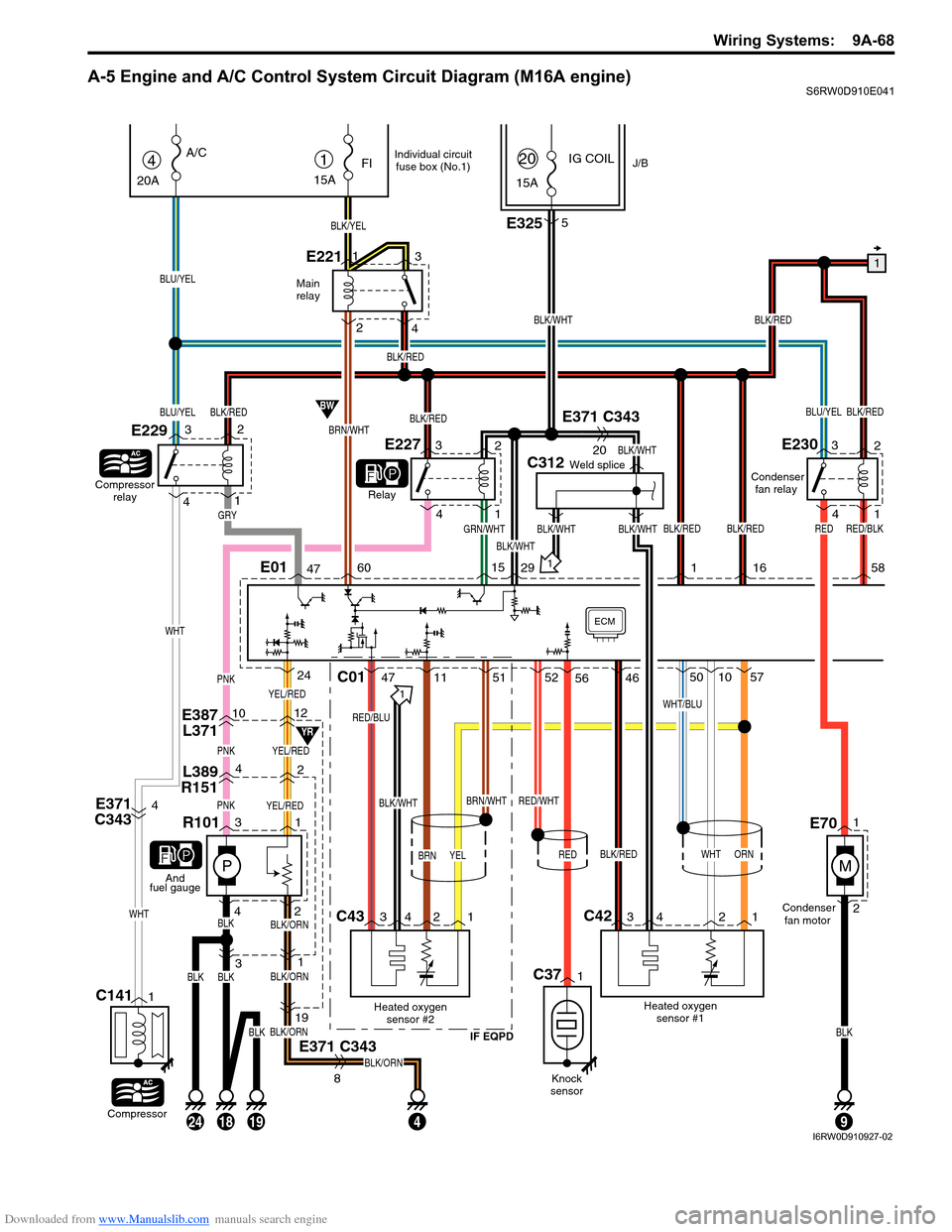
A-5 Engine and A/C Control System Circuit Diagram (M16A engine)S6RW0D910E041
YEL/RED
E387
L3711012
L389
R15142
PNKYEL/RED
P
PNKYEL/RED
31
4
31
E371 C343
BLK/ORN
BLK/ORN
BLK/ORN
BLK/ORN
19
8
BLK42
R101
1
And
fuel gauge
Main
relay
1
BLK/WHT
BLK/REDBLU/YEL
C312Weld splice
GRN/WHTBLK/WHT
BLK/WHT
BLK/WHT
IG COILJ/B1
15A
FI
BLK/YEL
E2211
23
415A
20
BRN/WHT
BW
YR
4
20A
A/C
Compressor
relay
E229
Relay
BLU/YEL
BLU/YEL
Compressor
C1411
E3255
E371 C343
20
E371
C3434BLK/WHT
C43C42
Heated oxygen
sensor #2
IF EQPD
RED/BLU
BRN
Heated oxygen
sensor #1Condenser
fan motor Condenser
fan relay
WHT
BRN/WHT
BLK/RED
WHT/BLU
C01
1
34 2 134 2 1
471151
RED/WHT
52461050
ORN
57PNK
ECM
142
3
WHT
WHT
BLK/RED
BLK/REDBLK/WHT
BLK/RED
BLK/RED
BLK/RED
E01476015291
GRY
E22732
4
1
E23032
4
1
YEL
24
BLKBLK
56
BLK/REDRED
16 58
182419
Individual circuit
fuse box (No.1)
BLKBLK
9
RED/BLK
M
1
2E70
RED
Knock
sensor
C371
I6RW0D910927-02