2006 SUZUKI SX4 front fog
[x] Cancel search: front fogPage 1383 of 1556
Downloaded from www.Manualslib.com manuals search engine Wipers / Washers: 9D-9
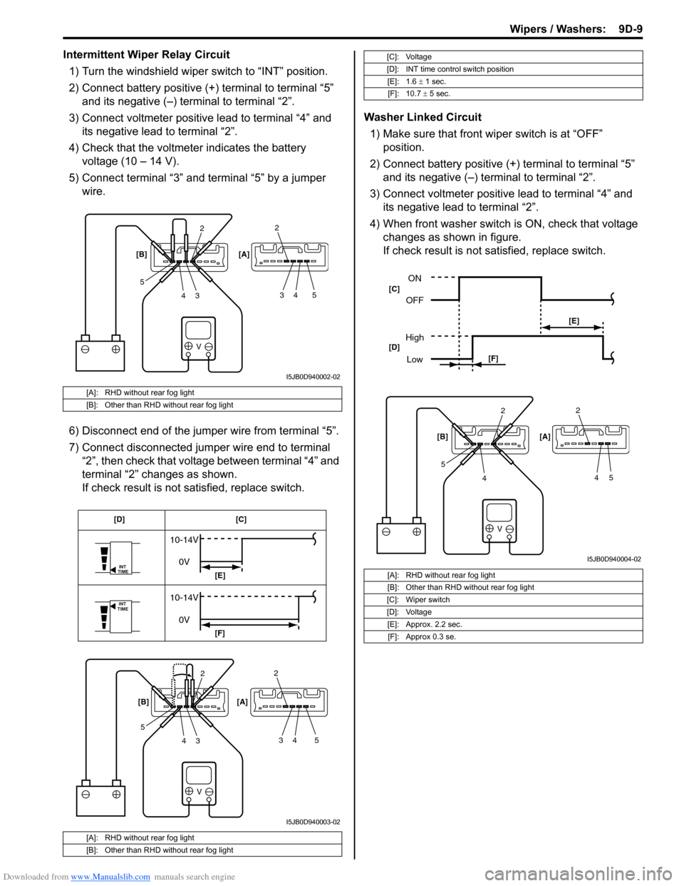
Intermittent Wiper Relay Circuit
1) Turn the windshield wiper switch to “INT” position.
2) Connect battery positive (+) terminal to terminal “5”
and its negative (–) terminal to terminal “2”.
3) Connect voltmeter positive lead to terminal “4” and
its negative lead to terminal “2”.
4) Check that the voltmeter indicates the battery
voltage (10 – 14 V).
5) Connect terminal “3” and terminal “5” by a jumper
wire.
6) Disconnect end of the jumper wire from terminal “5”.
7) Connect disconnected jumper wire end to terminal
“2”, then check that voltage between terminal “4” and
terminal “2” changes as shown.
If check result is not satisfied, replace switch.Washer Linked Circuit
1) Make sure that front wiper switch is at “OFF”
position.
2) Connect battery positive (+) terminal to terminal “5”
and its negative (–) terminal to terminal “2”.
3) Connect voltmeter positive lead to terminal “4” and
its negative lead to terminal “2”.
4) When front washer switch is ON, check that voltage
changes as shown in figure.
If check result is not satisfied, replace switch.
[A]: RHD without rear fog light
[B]: Other than RHD without rear fog light
[A]: RHD without rear fog light
[B]: Other than RHD without rear fog light
V
2
3 4 52
34 5 [B] [A]
I5JB0D940002-02
V
INT
TIME
INT
TIME
10-14V
0V
10-14V
0V
2
3 4 52
34 5 [B] [A][C] [D]
[E]
[F]
I5JB0D940003-02
[C]: Voltage
[D]: INT time control switch position
[E]: 1.6 ± 1 sec.
[F]: 10.7 ± 5 sec.
[A]: RHD without rear fog light
[B]: Other than RHD without rear fog light
[C]: Wiper switch
[D]: Voltage
[E]: Approx. 2.2 sec.
[F]: Approx 0.3 se.
V
2
4 52
45 [B] [A]
ON
OFF
High
Low
[E]
[F] [C]
[D]
I5JB0D940004-02
Page 1405 of 1556
Downloaded from www.Manualslib.com manuals search engine Glass / Windows / Mirrors: 9E-20
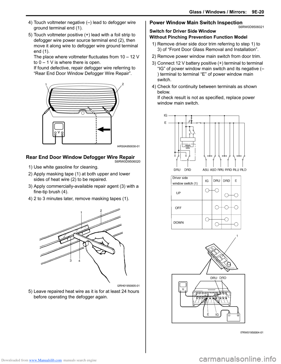
4) Touch voltmeter negative (–) lead to defogger wire
ground terminal end (1).
5) Touch voltmeter positive (+) lead with a foil strip to
defogger wire power source terminal end (2), then
move it along wire to defogger wire ground terminal
end (1).
The place where voltmeter fluctuates from 10 – 12 V
to 0 – 1 V is where there is open.
If found defective, repair defogger wire referring to
“Rear End Door Window Defogger Wire Repair”.
Rear End Door Window Defogger Wire RepairS6RW0D9506020
1) Use white gasoline for cleaning.
2) Apply masking tape (1) at both upper and lower
sides of heat wire (2) to be repaired.
3) Apply commercially-available repair agent (3) with a
fine-tip brush (4).
4) 2 to 3 minutes later, remove masking tapes (1).
5) Leave repaired heat wire as it is for at least 24 hours
before operating the defogger again.
Power Window Main Switch InspectionS6RW0D9506021
Switch for Driver Side Window
Without Pinching Prevention Function Model
1) Remove driver side door trim referring to step 1) to
3) of “Front Door Glass Removal and Installation”.
2) Remove power window main switch from door trim.
3) Connect 12 V battery positive (+) terminal to terminal
“IG” of power window main switch and its negative (–
) terminal to terminal “E” of power window main
switch.
4) Check for continuity between terminals as shown
below.
If check result is not as specified, replace power
window main switch.
21
I4RS0A950030-01
I2RH01950005-01
I7RW01950004-01
Page 1411 of 1556
Downloaded from www.Manualslib.com manuals search engine Glass / Windows / Mirrors: 9E-26
Door Mirror Heater Inspection (If Equipped)S6RW0D9506027
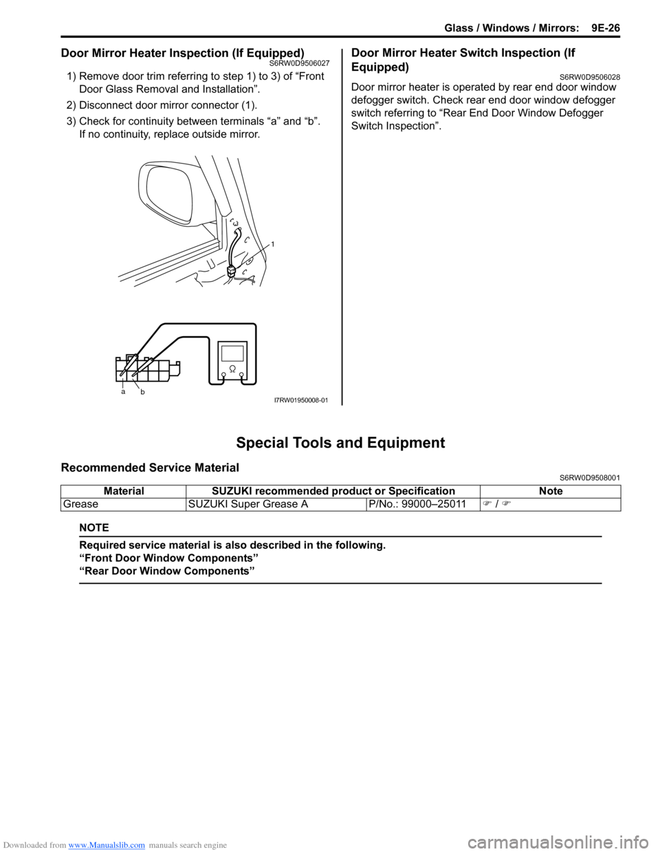
1) Remove door trim referring to step 1) to 3) of “Front
Door Glass Removal and Installation”.
2) Disconnect door mirror connector (1).
3) Check for continuity between terminals “a” and “b”.
If no continuity, replace outside mirror.
Door Mirror Heater Switch Inspection (If
Equipped)
S6RW0D9506028
Door mirror heater is operated by rear end door window
defogger switch. Check rear end door window defogger
switch referring to “Rear End Door Window Defogger
Switch Inspection”.
Special Tools and Equipment
Recommended Service MaterialS6RW0D9508001
NOTE
Required service material is also described in the following.
“Front Door Window Components”
“Rear Door Window Components”
a
b1I7RW01950008-01
Material SUZUKI recommended product or Specification Note
Grease SUZUKI Super Grease A P/No.: 99000–25011�) / �)
Page 1484 of 1556
Downloaded from www.Manualslib.com manuals search engine 10B-11 Body Electrical Control System:
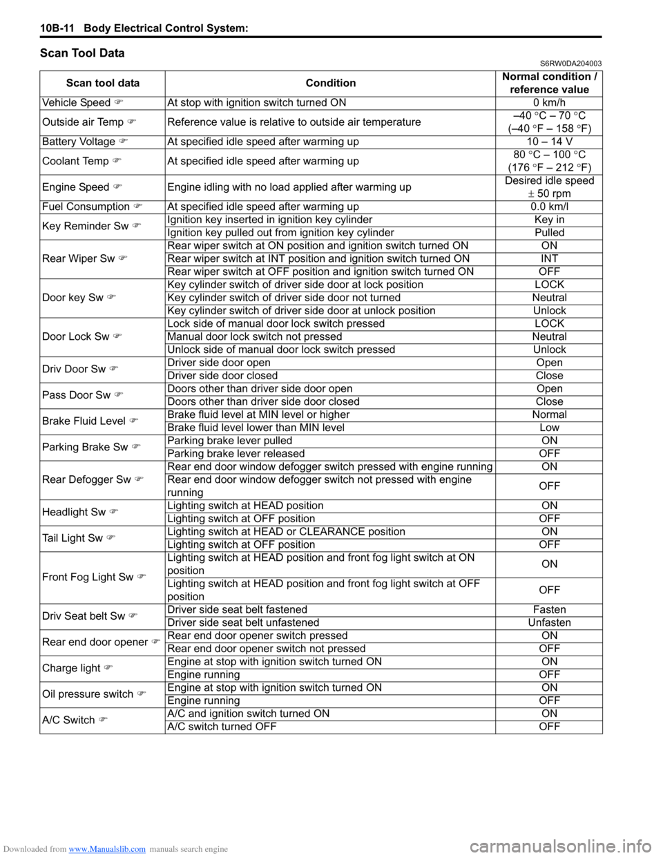
Scan Tool DataS6RW0DA204003
Scan tool data ConditionNormal condition /
reference value
Vehicle Speed �)At stop with ignition switch turned ON 0 km/h
Outside air Temp �)Reference value is relative to outside air temperature–40 °C – 70 °C
(–40 °F – 158 °F)
Battery Voltage �)At specified idle speed after warming up 10 – 14 V
Coolant Temp �)At specified idle speed after warming up80 °C – 100 °C
(176 °F – 212 °F)
Engine Speed �)Engine idling with no load applied after warming upDesired idle speed
± 50 rpm
Fuel Consumption �)At specified idle speed after warming up 0.0 km/l
Key Reminder Sw �)Ignition key inserted in ignition key cylinder Key in
Ignition key pulled out from ignition key cylinder Pulled
Rear Wiper Sw �)Rear wiper switch at ON position and ignition switch turned ON ON
Rear wiper switch at INT position and ignition switch turned ON INT
Rear wiper switch at OFF position and ignition switch turned ON OFF
Door key Sw �)Key cylinder switch of driver side door at lock position LOCK
Key cylinder switch of driver side door not turned Neutral
Key cylinder switch of driver side door at unlock position Unlock
Door Lock Sw �)Lock side of manual door lock switch pressed LOCK
Manual door lock switch not pressed Neutral
Unlock side of manual door lock switch pressed Unlock
Driv Door Sw �)Driver side door open Open
Driver side door closed Close
Pass Door Sw �)Doors other than driver side door open Open
Doors other than driver side door closed Close
Brake Fluid Level �)Brake fluid level at MIN level or higher Normal
Brake fluid level lower than MIN level Low
Parking Brake Sw �)Parking brake lever pulled ON
Parking brake lever released OFF
Rear Defogger Sw �)Rear end door window defogger switch pressed with engine running ON
Rear end door window defogger switch not pressed with engine
runningOFF
Headlight Sw �)Lighting switch at HEAD position ON
Lighting switch at OFF position OFF
Tail Light Sw �)Lighting switch at HEAD or CLEARANCE position ON
Lighting switch at OFF position OFF
Front Fog Light Sw �)Lighting switch at HEAD position and front fog light switch at ON
positionON
Lighting switch at HEAD position and front fog light switch at OFF
positionOFF
Driv Seat belt Sw
�)Driver side seat belt fastened Fasten
Driver side seat belt unfastened Unfasten
Rear end door opener �)Rear end door opener switch pressed ON
Rear end door opener switch not pressed OFF
Charge light �)Engine at stop with ignition switch turned ON ON
Engine running OFF
Oil pressure switch �)Engine at stop with ignition switch turned ON ON
Engine running OFF
A/C Switch �)A/C and ignition switch turned ON ON
A/C switch turned OFF OFF
Page 1485 of 1556
Downloaded from www.Manualslib.com manuals search engine Body Electrical Control System: 10B-12
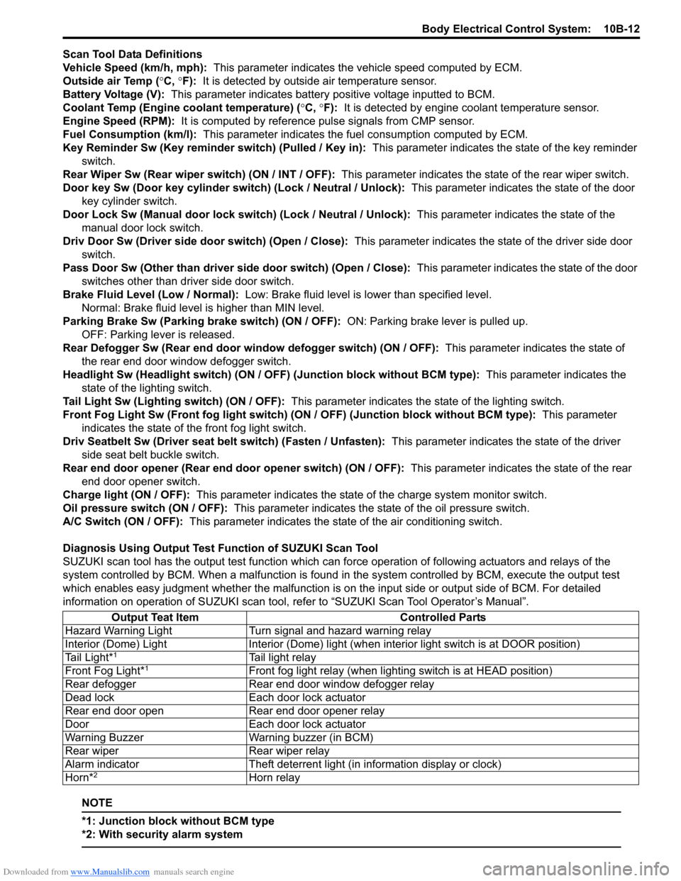
Scan Tool Data Definitions
Vehicle Speed (km/h, mph): This parameter indicates the vehicle speed computed by ECM.
Outside air Temp (°C, °F): It is detected by outside air temperature sensor.
Battery Voltage (V): This parameter indicates battery positive voltage inputted to BCM.
Coolant Temp (Engine coolant temperature) (°C, °F): It is detected by engine coolant temperature sensor.
Engine Speed (RPM): It is computed by reference pulse signals from CMP sensor.
Fuel Consumption (km/l): This parameter indicates the fuel consumption computed by ECM.
Key Reminder Sw (Key reminder switch) (Pulled / Key in): This parameter indicates the state of the key reminder
switch.
Rear Wiper Sw (Rear wiper switch) (ON / INT / OFF): This parameter indicates the state of the rear wiper switch.
Door key Sw (Door key cylinder switch) (Lock / Neutral / Unlock): This parameter indicates the state of the door
key cylinder switch.
Door Lock Sw (Manual door lock switch) (Lock / Neutral / Unlock): This parameter indicates the state of the
manual door lock switch.
Driv Door Sw (Driver side door switch) (Open / Close): This parameter indicates the state of the driver side door
switch.
Pass Door Sw (Other than driver side door switch) (Open / Close): This parameter indicates the state of the door
switches other than driver side door switch.
Brake Fluid Level (Low / Normal): Low: Brake fluid level is lower than specified level.
Normal: Brake fluid level is higher than MIN level.
Parking Brake Sw (Parking brake switch) (ON / OFF): ON: Parking brake lever is pulled up.
OFF: Parking lever is released.
Rear Defogger Sw (Rear end door window defogger switch) (ON / OFF): This parameter indicates the state of
the rear end door window defogger switch.
Headlight Sw (Headlight switch) (ON / OFF) (Junction block without BCM type): This parameter indicates the
state of the lighting switch.
Tail Light Sw (Lighting switch) (ON / OFF): This parameter indicates the state of the lighting switch.
Front Fog Light Sw (Front fog light switch) (ON / OFF) (Junction block without BCM type): This parameter
indicates the state of the front fog light switch.
Driv Seatbelt Sw (Driver seat belt switch) (Fasten / Unfasten): This parameter indicates the state of the driver
side seat belt buckle switch.
Rear end door opener (Rear end door opener switch) (ON / OFF): This parameter indicates the state of the rear
end door opener switch.
Charge light (ON / OFF): This parameter indicates the state of the charge system monitor switch.
Oil pressure switch (ON / OFF): This parameter indicates the state of the oil pressure switch.
A/C Switch (ON / OFF): This parameter indicates the state of the air conditioning switch.
Diagnosis Using Output Test Function of SUZUKI Scan Tool
SUZUKI scan tool has the output test function which can force operation of following actuators and relays of the
system controlled by BCM. When a malfunction is found in the system controlled by BCM, execute the output test
which enables easy judgment whether the malfunction is on the input side or output side of BCM. For detailed
information on operation of SUZUKI scan tool, refer to “SUZUKI Scan Tool Operator’s Manual”.
NOTE
*1: Junction block without BCM type
*2: With security alarm system
Output Teat Item Controlled Parts
Hazard Warning Light Turn signal and hazard warning relay
Interior (Dome) Light Interior (Dome) light (when interior light switch is at DOOR position)
Tail Light*
1Tail light relay
Front Fog Light*1Front fog light relay (when lighting switch is at HEAD position)
Rear defogger Rear end door window defogger relay
Dead lock Each door lock actuator
Rear end door open Rear end door opener relay
Door Each door lock actuator
Warning Buzzer Warning buzzer (in BCM)
Rear wiper Rear wiper relay
Alarm indicator Theft deterrent light (in information display or clock)
Horn*
2Horn relay