Page 1339 of 1556

Downloaded from www.Manualslib.com manuals search engine Lighting Systems: 9B-20
Igniter Removal and Installation (Discharge
Headlight Model)
S6RW0D9206024
WARNING!
Be sure to read “Precautions for Discharge
Headlight Service (If Equipped)” carefully
before working. Neglecting them may result
in personal injury.
Removal
1) Remove ballast referring to “Ballast Removal and
Installation (Discharge Headlight Model)”.
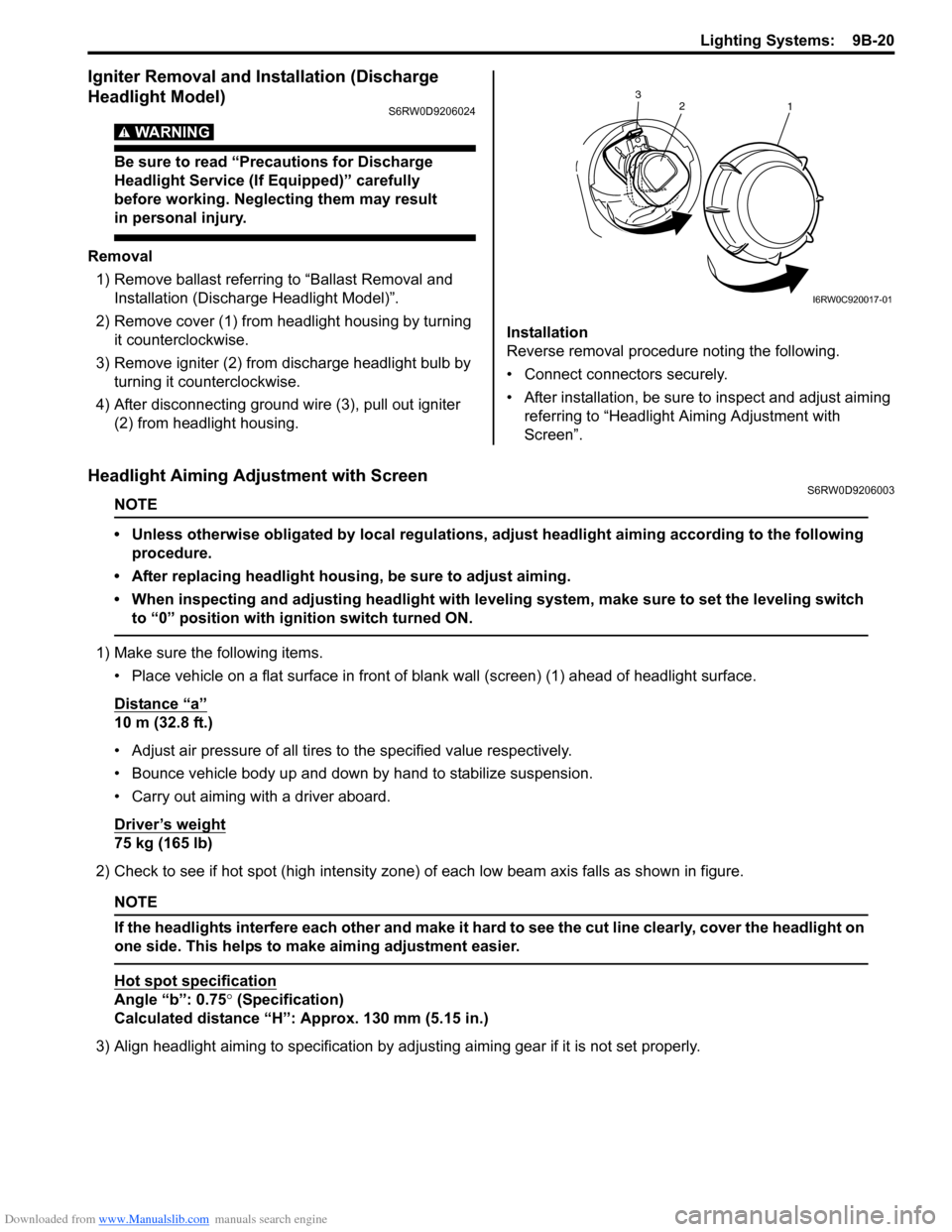
2) Remove cover (1) from headlight housing by turning
it counterclockwise.
3) Remove igniter (2) from discharge headlight bulb by
turning it counterclockwise.
4) After disconnecting ground wire (3), pull out igniter
(2) from headlight housing.Installation
Reverse removal procedure noting the following.
• Connect connectors securely.
• After installation, be sure to inspect and adjust aiming
referring to “Headlight Aiming Adjustment with
Screen”.
Headlight Aiming Adjustment with ScreenS6RW0D9206003
NOTE
• Unless otherwise obligated by local regulations, adjust headlight aiming according to the following
procedure.
• After replacing headlight housing, be sure to adjust aiming.
• When inspecting and adjusting headlight with leveling system, make sure to set the leveling switch
to “0” position with ignition switch turned ON.
1) Make sure the following items.
• Place vehicle on a flat surface in front of blank wall (screen) (1) ahead of headlight surface.
Distance “a”
10 m (32.8 ft.)
• Adjust air pressure of all tires to the specified value respectively.
• Bounce vehicle body up and down by hand to stabilize suspension.
• Carry out aiming with a driver aboard.
Driver’s weight
75 kg (165 lb)
2) Check to see if hot spot (high intensity zone) of each low beam axis falls as shown in figure.
NOTE
If the headlights interfere each other and make it hard to see the cut line clearly, cover the headlight on
one side. This helps to make aiming adjustment easier.
Hot spot specification
Angle “b”: 0.75° (Specification)
Calculated distance “H”: Approx. 130 mm (5.15 in.)
3) Align headlight aiming to specification by adjusting aiming gear if it is not set properly.
2
1 3
I6RW0C920017-01
Page 1345 of 1556

Downloaded from www.Manualslib.com manuals search engine Lighting Systems: 9B-26
Front Fog Light Assembly Removal and
Installation (If Equipped)
S6RW0D9206014
WARNING!
• To avoid danger of being burned, don’t
touch when the bulb is hot.
• Don’t touch glass surface of bulb to avoid
deteriorate as the case may be unclear
when bulb light on at dirty condition.
Removal
1) Disconnect negative (–) cable at battery.
2) Remove front bumper. Refer to “Front Bumper and
Rear Bumper Components in Section 9K”.
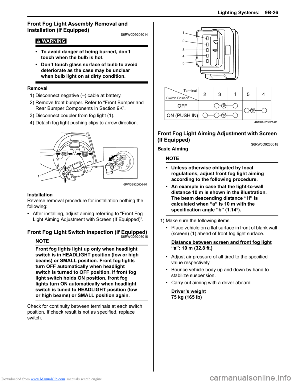
3) Disconnect coupler from fog light (1).
4) Detach fog light pushing clips to arrow direction.
Installation
Reverse removal procedure for installation nothing the
following:
• After installing, adjust aiming referring to “Front Fog
Light Aiming Adjustment with Screen (If Equipped)”.
Front Fog Light Switch Inspection (If Equipped)S6RW0D9206016
NOTE
Front fog lights light up only when headlight
switch is in HEADLIGHT position (low or high
beams) or SMALL position. Front fog lights
turn OFF automatically when headlight
switch is turned to OFF position. If front fog
light switch holds ON position, front fog
lights turn ON automatically when headlight
switch is tuned to HEADLIGHT position (low
or high beams) or SMALL position again.
Check for continuity between terminals at each switch
position. If check result is not as specified, replace
switch.
Front Fog Light Aiming Adjustment with Screen
(If Equipped)
S6RW0D9206018
Basic Aiming
NOTE
• Unless otherwise obligated by local
regulations, adjust front fog light aiming
according to the following procedure.
• An example in case that the light-to-wall
distance 10 m is shown in the illustration.
The beam descending distance “H” is
calculated when “a” is 10 m with the
specification angle “b” (1.14°).
1) Make sure the following items.
• Place vehicle on a flat surface in front of blank wall
(screen) (1) ahead of front fog light surface.
Distance between screen and front fog light
“a”: 10 m (32.8 ft.)
• Adjust air pressure of all tired to the specified
value respectively.
• Bounce vehicle body up and down by hand to
stabilize suspension.
• Carry out aiming with a driver aboard.
Driver’s weight
75 kg (165 lb)
1
I6RW0B920006-01
1
2
3
4
5
Switch PositionTerminal
ON (PUSH IN)231
54
OFF
I4RS0A920021-01
Page 1350 of 1556

Downloaded from www.Manualslib.com manuals search engine 9B-31 Lighting Systems:
Without initialization of the headlight auto leveling
system, it is not possible to obtain its proper function.
Also, if the headlight auto leveling system is not
initialized after replacing the headlight leveling control
module, the headlight leveling warning light in the
combination meter flashes.
1) Observe the following instructions.
• Park vehicle on level ground.
• Adjust air pressure of all tires to the specified
value respectively.
• Bounce vehicle body up and down by hand to
stabilize suspension.
2) Turn ignition switch to ON position.
3) Perform “Headlight Leveling Warning Light Check”.
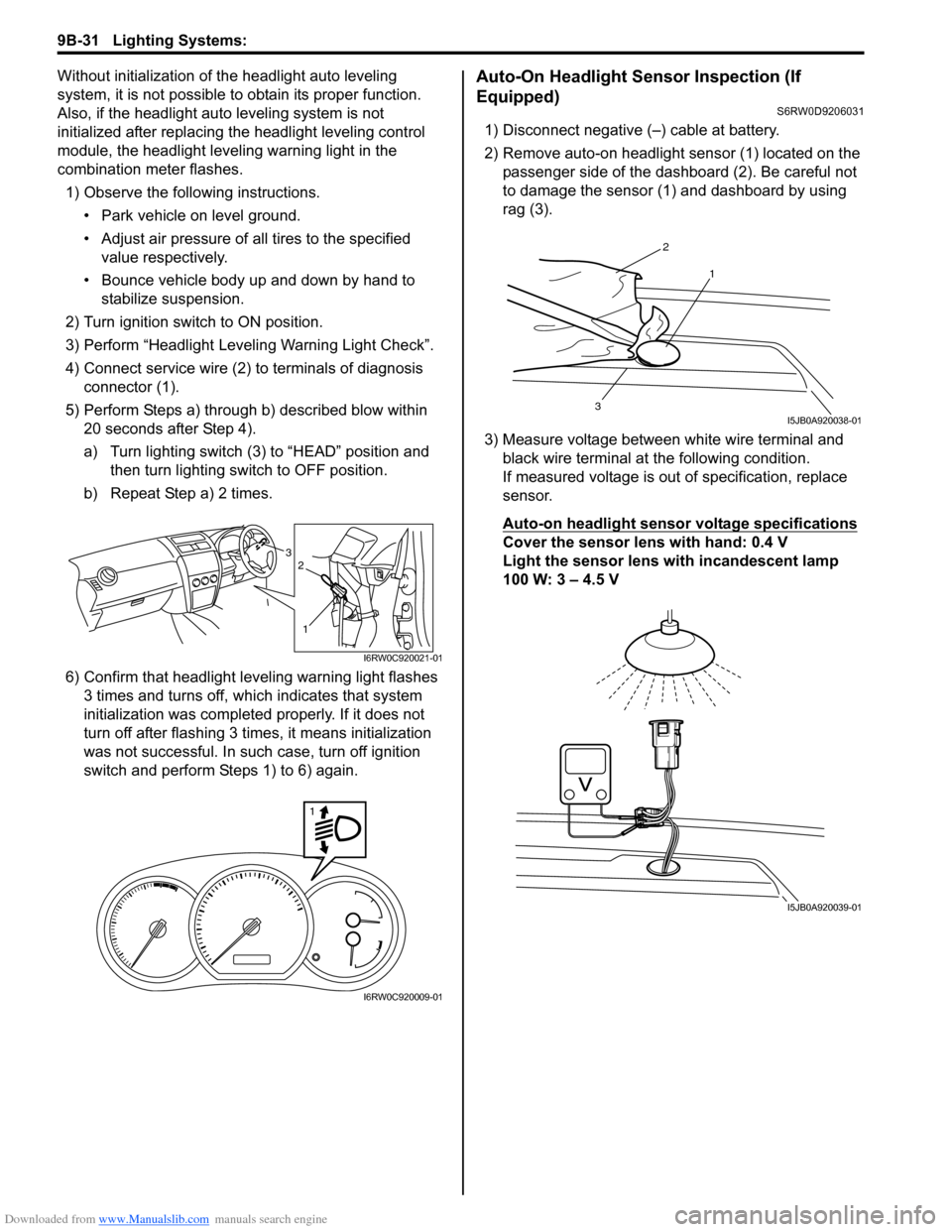
4) Connect service wire (2) to terminals of diagnosis
connector (1).
5) Perform Steps a) through b) described blow within
20 seconds after Step 4).
a) Turn lighting switch (3) to “HEAD” position and
then turn lighting switch to OFF position.
b) Repeat Step a) 2 times.
6) Confirm that headlight leveling warning light flashes
3 times and turns off, which indicates that system
initialization was completed properly. If it does not
turn off after flashing 3 times, it means initialization
was not successful. In such case, turn off ignition
switch and perform Steps 1) to 6) again.Auto-On Headlight Sensor Inspection (If
Equipped)
S6RW0D9206031
1) Disconnect negative (–) cable at battery.
2) Remove auto-on headlight sensor (1) located on the
passenger side of the dashboard (2). Be careful not
to damage the sensor (1) and dashboard by using
rag (3).
3) Measure voltage between white wire terminal and
black wire terminal at the following condition.
If measured voltage is out of specification, replace
sensor.
Auto-on headlight sensor voltage specifications
Cover the sensor lens with hand: 0.4 V
Light the sensor lens with incandescent lamp
100 W: 3 – 4.5 V3
1
2
I6RW0C920021-01
1
I6RW0C920009-01
2
1
3I5JB0A920038-01
I5JB0A920039-01