2006 SUZUKI SX4 air suspension
[x] Cancel search: air suspensionPage 303 of 1556

Downloaded from www.Manualslib.com manuals search engine Engine Mechanical: 1D-21
12) Install oil pressure switch bracket (1).
13) Connect right and left drive shaft joints to differential
gear referring to “Front Drive Shaft Assembly
Removal and Installation in Section 3A”.
14) Install suspension control arm referring to
“Suspension Control Arm / Bushing Removal and
Installation in Section 2B”.
15) Install cylinder upper cover (1).16) Install A/C compressor to its bracket (if equipped)
referring to “Compressor Assembly Removal and
Installation in Section 7B” or “Compressor Assembly
Removal and Installation in Section 7B”.
17) Adjust A/C compressor drive belt referring to
“Compressor Drive Belt Removal and Installation in
Section 7B” or “Compressor Drive Belt Removal and
Installation in Section 7B”.
18) Install air cleaner assembly referring to “Air Cleaner
Assembly Removal and Installation”.
19) Check to ensure that all removed parts are back in
place. Reinstall any necessary parts which have not
been reinstalled.
20) Refill cooling system with coolant referring to
“Cooling System Flush and Refill in Section 1F”.
21) Refill engine with engine oil referring to “Engine Oil
and Filter Change in Section 0B”.
22) Refill transaxle oil referring to “Manual Transaxle Oil
Change in Section 5B” or “A/T Fluid Change in
Section 5A”.
23) Refill transfer oil referring to “Transfer Oil Change in
Section 3C”.
24) Install battery and battery tray with ECM.
25) Connect ECM wire harness.
26) Connect positive and negative cable at battery.
27) Install right and left side engine under covers.
28) Verify that there is no fuel leakage, coolant leakage,
oil leakage and exhaust gas leakage at each
connection.
2. Exhaust manifold
1
2
I5RW0A140011-01
1
I5RW0A140009-01
Page 433 of 1556

Downloaded from www.Manualslib.com manuals search engine Table of Contents 2- i
2
Section 2
CONTENTS
Suspension
Precautions ................................................. 2-1
Precautions............................................................. 2-1
Precautions on Suspension .................................. 2-1
Suspension General Diagnosis.............. 2A-1
Diagnostic Information and Procedures ............ 2A-1
Suspension, Wheels and Tires Symptom
Diagnosis .......................................................... 2A-1
Specifications....................................................... 2A-3
Wheel Alignment Specifications .......................... 2A-3
Front Suspension .................................... 2B-1
General Description ............................................. 2B-1
Front Suspension Construction ........................... 2B-1
Front Wheel Alignment Construction .................. 2B-2
Repair Instructions .............................................. 2B-2
Front Wheel Alignment Inspection and
Adjustment ........................................................ 2B-2
Front Strut Assembly Components ..................... 2B-4
Front Strut Assembly Removal and
Installation ......................................................... 2B-5
Front Strut Assembly Disassembly and
Reassembly ...................................................... 2B-7
Front Strut Assembly Check ............................... 2B-8
Front Wheel Hub and Steering Knuckle
Components...................................................... 2B-9
Front Wheel Hub, Steering Knuckle and
Wheel Bearing Removal and Installation .......... 2B-9
Front Wheel Hub, Disc, Bolt and Bearing
Check .............................................................. 2B-14
Suspension Control Arm / Bushing Removal
and Installation ................................................ 2B-14
Suspension Control Arm / Bushing
Disassembly and Assembly ............................ 2B-15
Suspension Control Arm / Steering Knuckle
Check .............................................................. 2B-16
Suspension Control Arm Bushing Check .......... 2B-16
Suspension Control Arm Joint Check ............... 2B-16
Front Suspension Frame, Stabilizer Bar and/
or Bushing Components ................................. 2B-17
Front Suspension Frame, Stabilizer Bar and/
or Bushing Removal and Installation .............. 2B-18
Front Suspension Frame Check ....................... 2B-20
Front Stabilizer Bar, Bushing and/or Joint
Check .............................................................. 2B-20Front Suspension Fasteners Check .................. 2B-20
Specifications .....................................................2B-21
Tightening Torque Specifications ...................... 2B-21
Special Tools and Equipment ...........................2B-22
Recommended Service Material ....................... 2B-22
Special Tool ...................................................... 2B-22
Rear Suspension ..................................... 2C-1
Repair Instructions ..............................................2C-1
Rear Suspension Components ...........................2C-1
Rear Shock Absorber Removal and
Installation .........................................................2C-2
Rear Shock Absorber Inspection ........................2C-3
Rear Shock Absorber Bush Inspection ...............2C-3
Rear Coil Spring Removal and Installation .........2C-4
Spring Upper Seat / Spring Lower Seat
Inspection ..........................................................2C-5
Rear Axle Removal and Installation ....................2C-6
Rear Axle and Coil Spring Inspection .................2C-7
Rear Axle Bush Inspection ..................................2C-7
Rear Wheel Disc, Bolt and Bearing Inspection ....2C-7
Rear Wheel Hub Assembly Removal and
Installation .........................................................2C-8
Specifications .....................................................2C-10
Tightening Torque Specifications ......................2C-10
Wheels and Tires ..................................... 2D-1
General Description .............................................2D-1
Tires Description .................................................2D-1
Wheels Description .............................................2D-2
Irregular and/or Premature Wear Description .....2D-3
Wear Indicators Description ................................2D-3
Radial Tire Waddle Description...........................2D-3
Radial Tire Lead / Pull Description ......................2D-4
Balancing Wheels Description ............................2D-4
Repair Instructions ..............................................2D-5
Wheel Discs Inspection .......................................2D-5
Wheel Balance Inspection and Adjustment.........2D-5
Tire Rotation........................................................2D-5
Wheel (with Tire) Removal and Installation.........2D-6
Tire Mounting and Dismounting ..........................2D-6
Tire Repair ..........................................................2D-6
Specifications .......................................................2D-7
Wheels and Tires Specifications .........................2D-7
Tightening Torque Specifications ........................2D-7
Page 435 of 1556

Downloaded from www.Manualslib.com manuals search engine Suspension General Diagnosis: 2A-1
Suspension
Suspension General Diagnosis
Diagnostic Information and Procedures
Suspension, Wheels and Tires Symptom DiagnosisS6RW0D2104001
Condition Possible cause Correction / Reference Item
Vehicle pulls (Leads)Mismatched or uneven tiresReplace tires.
Tires not adequately inflatedAdjust tire pressure.
Broken or sagging coil springsReplace coil springs.
Radial tire lateral forceReplace tire.
Disturbed wheel alignmentCheck and adjust wheel alignment.
Brake dragging in one road wheelRepair brake.
Loose, bent or broken front or rear
suspension partsTighten or replace related suspension parts.
Abnormal or excessive
tire wearSagging or broken coil springReplace coil spring.
Tire out of balanceAdjust balance or replace tire.
Disturbed wheel alignmentCheck and adjust wheel alignment.
Faulty strut (shock absorber)Replace strut (shock absorber).
Hard drivingReplace tires.
Overloaded vehicleReplace tires.
Not rotated tiresReplace or rotate tires.
Worn or loose wheel bearingReplace wheel bearing.
Wobbly wheel or tireReplace wheel or tire.
Tires not adequately inflatedAdjust tire pressure.
Front suspension frame and/or
suspension control arm are transformedCheck and replace.
Wheel trampBlister or bump on tireReplace tire.
Improper strut (shock absorber) actionReplace strut (shock absorber).
Shimmy, shake or
vibrationTire or wheel out of balanceBalance wheel or replace tire and/or wheel.
Loosen wheel bearingsReplace wheel bearings.
Worn tie-rod endsReplace tie-rod ends.
Worn lower ball jointsReplace suspension control arm.
Excessive wheel runoutRepair or replace wheel and/or tire.
Blister or bump on tireReplace tire.
Excessively loaded radial runout of tire /
wheel assemblyReplace tire or wheel.
Disturbed wheel alignmentCheck and adjust wheel alignment.
Loose or worn steering linkageTighten or replace steering linkage.
Abnormal noise, front endWorn, sticky or loose tie-rod ends, lower
ball joints, tie-rod inside ball joints or
drive shaft jointsReplace tie-rod end, suspension arm, tie-rod
or drive shaft joint.
Damaged struts or mountingsRepair or replace struts or mountings.
Worn suspension arm bushingsReplace suspension arm bushings.
Loose stabilizer barTighten bolts or nuts and/or replace bushes.
Loose wheel boltsTighten wheel bolts.
Loose suspension bolts or nutsTighten suspension bolts or nuts.
Broken or damaged wheel bearingsReplace wheel bearings.
Broken suspension springsReplace suspension springs.
Worn strut bearingsReplace strut bearing.
Malfunction of Power Steering SystemCheck and correct malfunction.
Low or uneven trim height
NOTE
See NOTE *1.
Broken or sagging coil springsReplace coil springs.
Over loadedCheck loading.
Incorrect coil springsReplace coil spring.
Tires not adequately inflatedAdjust tire pressure.
Ride too softFaulty strut (shock absorber)Replace strut (shock absorber).
Suspension bottomsOverloadedCheck loading.
Faulty strut (shock absorber)Replace strut (shock absorber).
Incorrect, broken or sagging coil springsReplace coil spring.
Page 439 of 1556

Downloaded from www.Manualslib.com manuals search engine Front Suspension: 2B-2
Front Wheel Alignment ConstructionS6RW0D2201002
Among factors for front wheel alignment, only toe setting
can be adjusted. Camber and caster are not adjustable.
Therefore, should camber or caster be out of
specification due to the damage caused by hazardous
road conditions or collision, whether the damage is in
body or in suspension should be determined and
damaged body should be repaired or damaged
suspension should be replaced.
Preliminary Checks Prior to Adjustment Front Wheel
Alignment
Steering and vibration complaints are not always the
result of improper wheel alignment. An additional item to
be checked is the possibility of tire lead due to worn or
improperly manufactured tires. “Lead” is the vehicle
deviation from a straight path on a level road without
hand pressure on the steering wheel. Refer to “Radial
Tire Lead / Pull Description in Section 2D” in order to
determine if the vehicle has a tire lead problem. Before
making any adjustment affecting wheel alignment, the
following checks and inspections should be made to
ensure correctness of alignment readings and alignment
adjustments:• Check all tires for proper inflation pressures and
approximately the same tread wear.
• Check for loose of ball joints. Check tie-rod ends; if
excessive looseness is noted, it must be corrected
before adjusting.
• Check for run-out of wheels and tires.
• Check vehicle trim heights; if it is out of limit and a
correction is needed, it must be done before adjusting
toe.
• Check for loose of suspension control arms.
• Check for loose or missing stabilizer bar attachments.
• Consideration must be given to excess loads, such as
tool boxes. If this excess load is normally carried in
vehicle, it should remain in vehicle during alignment
checks.
• Consider condition of equipment being used to check
alignment and follow manufacturer’s instructions.
• Regardless of equipment used to check alignment,
vehicle must be placed on a level surface.
NOTE
To prevent possible incorrect reading of toe,
camber or caster, vehicle front and rear end
must be moved up and down a few times
before inspection.
Repair Instructions
Front Wheel Alignment Inspection and
Adjustment
S6RW0D2206001
Toe Inspection and Adjustment
Preparation for toe inspection and adjustment.
• Place vehicle in unloaded state on level surface.
• Set steering wheel in straight state.
• Check that inflation pressure of each tire is adjusted
properly and wheel is free from deflection.
• Check that each suspension part is free from bend,
dent, wear or damage in any other form.
• Check that ground clearance at the right and left is
just about the same.Inspection
Measure toe with toe-in gauge (1).
Toe should be within following specifications.
If toe is out of the specification, adjust toe properly.
To e
IN 1.0 ± 1.0 mm (0.0394 ± 0.0394 in.)
I2RH01220062-01
Page 455 of 1556

Downloaded from www.Manualslib.com manuals search engine Front Suspension: 2B-18
Front Suspension Frame, Stabilizer Bar and/or
Bushing Removal and Installation
S6RW0D2206015
WARNING!
When supporting and installing front
suspension frame, be sure to apply some
supporting equipment (such as mission jack)
at well-balanced position in the center
section of front suspension frame so as to
prevent from its drop. Otherwise drop and
injure.
CAUTION!
When removal and installing suspension
control arm, be careful not to damage dust
boots of suspension control arm joint by
drive shaft dust cover and brake dust cover.
Removal
1) Disconnect negative (–) cable at battery.
2) Remove air cleaner assembly referring to “Air
Cleaner Assembly Removal and Installation in
Section 1D”.
3) Remove hood referring to “Hood Removal and
Installation in Section 9J”.
4) Hoist vehicle and remove front wheels.
5) Remove exhaust No.1, No.2 and center pipes
referring to “Exhaust System Components in Section
1K”.
6) Remove steering gear case mounting bolt referring
to “Steering Gear Case Assembly Components in
Section 6C”.
7) Fix steering gear case to body with rope to avoid the
steering gear case fall off when front suspension
frame is lowered.
8) Remove suspension control arms and disconnect
stabilizer joints.
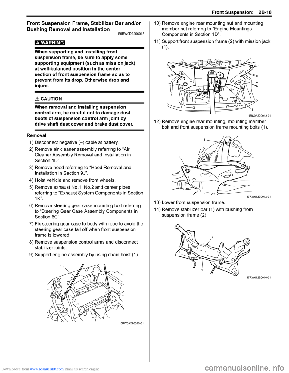
9) Support engine assembly by using chain hoist (1).10) Remove engine rear mounting nut and mounting
member nut referring to “Engine Mountings
Components in Section 1D”.
11) Support front suspension frame (2) with mission jack
(1).
12) Remove engine rear mounting, mounting member
bolt and front suspension frame mounting bolts (1).
13) Lower front suspension frame.
14) Remove stabilizer bar (1) with bushing from
suspension frame (2).
1
I5RW0A220026-01
2
1
I4RS0A220042-01
1
1
I7RW01220012-01
12
I7RW01220016-01
Page 457 of 1556

Downloaded from www.Manualslib.com manuals search engine Front Suspension: 2B-20
12) Install exhaust No.1, No.2 and center pipe referring
to “Exhaust System Components in Section 1K”.
13) Install wheel and tighten nut to specified torque.
Tightening torque
Wheel nut: 85 N·m (8.5 kgf-m, 61.5 lb-ft)
14) Install air cleaner assembly referring to “Air Cleaner
Assembly Removal and Installation in Section 1D”.
15) Install hood referring to “Hood Removal and
Installation in Section 9J”.
16) Lower hoist and vehicle in unloaded condition,
tighten suspension control arm bolts to specified
torque.
Tightening torque
Suspension control arm bolt: 95 N·m (9.5 kgf-m,
69.0 lb-ft)
17) Connect negative (–) cable at battery.
18) Confirm front wheel alignment referring to “Front
Wheel Alignment Inspection and Adjustment”.
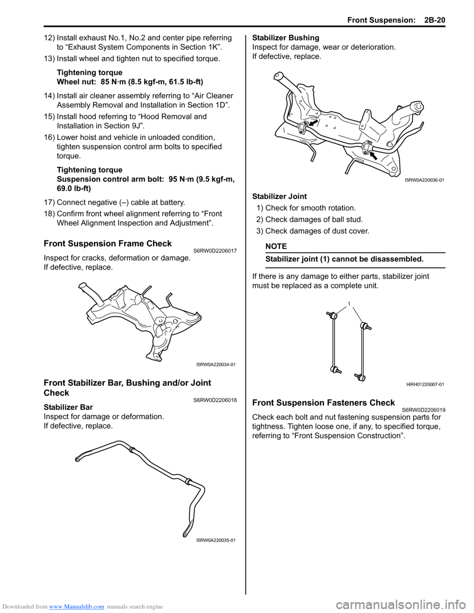
Front Suspension Frame CheckS6RW0D2206017
Inspect for cracks, deformation or damage.
If defective, replace.
Front Stabilizer Bar, Bushing and/or Joint
Check
S6RW0D2206018
Stabilizer Bar
Inspect for damage or deformation.
If defective, replace.Stabilizer Bushing
Inspect for damage, wear or deterioration.
If defective, replace.
Stabilizer Joint
1) Check for smooth rotation.
2) Check damages of ball stud.
3) Check damages of dust cover.
NOTE
Stabilizer joint (1) cannot be disassembled.
If there is any damage to either parts, stabilizer joint
must be replaced as a complete unit.
Front Suspension Fasteners CheckS6RW0D2206019
Check each bolt and nut fastening suspension parts for
tightness. Tighten loose one, if any, to specified torque,
referring to “Front Suspension Construction”.
I5RW0A220034-01
I5RW0A220035-01
I5RW0A220036-01
1
I4RH01220007-01
Page 460 of 1556

Downloaded from www.Manualslib.com manuals search engine 2C-1 Rear Suspension:
Suspension
Rear Suspension
Repair Instructions
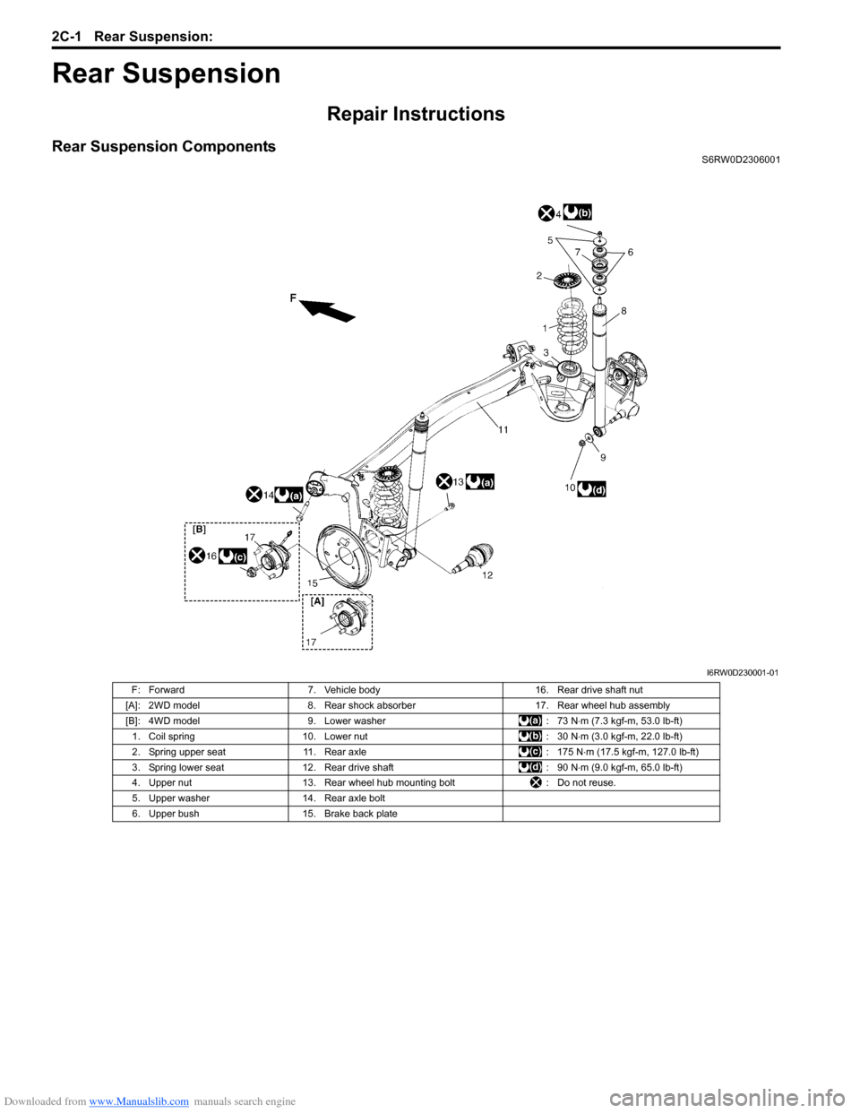
Rear Suspension ComponentsS6RW0D2306001
I6RW0D230001-01
F: Forward 7. Vehicle body 16. Rear drive shaft nut
[A]: 2WD model 8. Rear shock absorber 17. Rear wheel hub assembly
[B]: 4WD model 9. Lower washer : 73 N⋅m (7.3 kgf-m, 53.0 lb-ft)
1. Coil spring 10. Lower nut : 30 N⋅m (3.0 kgf-m, 22.0 lb-ft)
2. Spring upper seat 11. Rear axle : 175 N⋅m (17.5 kgf-m, 127.0 lb-ft)
3. Spring lower seat 12. Rear drive shaft : 90 N⋅m (9.0 kgf-m, 65.0 lb-ft)
4. Upper nut 13. Rear wheel hub mounting bolt : Do not reuse.
5. Upper washer 14. Rear axle bolt
6. Upper bush 15. Brake back plate
Page 466 of 1556

Downloaded from www.Manualslib.com manuals search engine 2C-7 Rear Suspension:
6) Connect rear height sensor link (if equipped) to rear
axle referring to “Height Sensor Removal and
Installation (If Equipped) in Section 9B”.
7) Install exhaust center pipe and muffler.
8) After installing removed parts, bleed air from brake
system referring to “Air Bleeding of Brake System in
Section 4A”. And then adjust parking brake cable
referring to “Parking Brake Inspection and
Adjustment in Section 4D”.
9) Install wheel and tighten wheel nuts to specified
torque.
Tightening torque
Wheel nut: 85 N·m (8.5 kgf-m, 61.5 lb-ft)
10) Lower hoist and bounce vehicle up and down
several times to stabilize suspension.
11) Tightening shock absorber lower nuts and rear axle
bolts to specified torque.
NOTE
When tightening these nuts and bolts, be
sure that vehicle is not on hoist and in
unloaded condition.
Tightening torque
Rear shock absorber lower nut: 90 N·m (9.0 kgf-
m, 65.0 lb-ft)
Rear axle bolt: 73 N·m (7.3 kgf-m, 53.0 lb-ft)
12) Perform brake test (foot brake and parking brake).
13) Check each installed parts for brake fluid leakage.
Rear Axle and Coil Spring InspectionS6RW0D2306009
• Inspect for cracks, deformation or damage.
• Inspect bushing for damage, wear or breakage.
Replace any defective part.
Rear Axle Bush InspectionS6RW0D2306010
Inspect for cracks, deformation or damage. If necessary,
replace rear axle assembly.
Rear Wheel Disc, Bolt and Bearing InspectionS6RW0D2306011
• Check tightness of wheel nuts and, if necessary,
retighten to specified torque.
• Check wheel disc deformation, damage, crack and
etc.
Replace defective disc with new one.
• Check installation face inside of wheel disc for rust.
As rust affects adversely, remove it thoroughly.
Tightening torque
Wheel nut: 85 N·m (8.5 kgf-m, 61.5 lb-ft)
• Check wear of wheel bearings. When measuring
thrust play, apply a dial gauge to axle shaft center.
When the thrust play exceeds limit, replace bearing.
Rear wheel bearing thrust play
Limit: 0.1 mm (0.004 in.)
• Check noise and smooth rotation of wheel by rotating
wheel. If it is defective, replace bearing.
(a)I5RW0A230022-01
I3RM0A230049-01
I3RM0A230050-01