2006 SUZUKI SX4 torque
[x] Cancel search: torquePage 977 of 1556

Downloaded from www.Manualslib.com manuals search engine Air Conditioning System: Manual Type 7B-37
Specifications
Tightening Torque SpecificationsS6RW0D7217001
NOTE
The specified tightening torque is also described in the following.
“A/C System Major Components Location”
“Compressor Assembly Components”
Reference:
For the tightening torque of fastener not specified in this section, refer to “Fasteners Information in Section 0A”.
Special Tools and Equipment
Recommended Service MaterialS6RW0D7218001
NOTE
Required service material is also described in the following.
“HVAC Unit Components”
“Compressor Assembly Components”
Special ToolS6RW0D7218002
Fastening partTightening torque
Note
N⋅mkgf-mlb-ft
Expansion valve bolt 4.5 0.45 3.5�)
A/C refrigerant pressure sensor 11 1.1 8.0�)
Compressor mounting bolt 25 2.5 18.0�)
Armature plate nut 16 1.6 11.5�)
Relief valve 8 0.8 6.0�)
Material SUZUKI recommended product or Specification Note
Compressor oil MATSUSHITADENKI GU10 P/No.: 99000–99015–
00A�)
Silicon sealant SUZUKI SILICON SEALANT KE-
347W (100g)P/No.: 99000–34220�)
09900–06107 09990–06020
Snap ring pliers (opening
type)Manifold gauge set (R134a)
�) / �) / �) / �) / �)1.Manifold gauge
2.Charging hoses 3.Quick
connector 4.Refrigerant
container tap valve
5.Refrigerant container T
joint 6.Packing sets 7.Case
�)
09990–86012 09991–06310
Gas leak detector Armature plate holder
This kit includes following
items.1. Gas leak detector,
2. Instruction manual, 3.
Filter, 4. Sensor, 5. Dri-sell
battery (size D) �) / �)�) / �)
12
34
5
Page 1029 of 1556
Downloaded from www.Manualslib.com manuals search engine Table of Contents 8- i
8
Section 8
CONTENTS
Restraint
Precautions ................................................. 8-1
Precautions............................................................. 8-1
Precautions on Restraint ....................................... 8-1
Seat Belts ................................................. 8A-1
Precautions........................................................... 8A-1
Precautions on Service and Diagnosis of Seat
Belt .................................................................... 8A-1
General Description ............................................. 8A-2
Seat Belt Construction ........................................ 8A-2
Diagnostic Information and Procedures ............ 8A-3
Repair and Inspection Required after
Accident ............................................................ 8A-3
Repair Instructions .............................................. 8A-4
Front Seat Belt Components ............................... 8A-4
Front Seat Belt Removal and Installation ............ 8A-5
Front Seat Belt Inspection................................... 8A-6
Rear Seat Belt Components ............................... 8A-7
Rear Seat Belt Removal and Installation ............ 8A-8
Rear Seat Belt Inspection ................................... 8A-8
Specifications....................................................... 8A-8
Tightening Torque Specifications ........................ 8A-8
Air Bag System ........................................ 8B-1
Precautions........................................................... 8B-1
Precautions on Service and Diagnosis of Air
Bag System....................................................... 8B-1
Precautions on Handling and Storage of Air
Bag System Components ................................. 8B-1
Precautions on Disposal of Air Bag and Seat
Belt Pretensioner .............................................. 8B-5
General Description ............................................. 8B-5
Air Bag System Construction .............................. 8B-5
Air Bag System Block Diagram ........................... 8B-6
Air Bag System Input / Output Table .................. 8B-7
Schematic and Routing Diagram ........................ 8B-8
Air Bag System Wiring Circuit Diagram .............. 8B-8
Component Location ......................................... 8B-11
Air Bag System Components, Wiring and
Connectors Location ....................................... 8B-11
Diagnostic Information and Procedures .......... 8B-12
Air Bag Diagnostic System Check .................... 8B-12
Air Bag Diagnostic System Check Flow ............ 8B-13
DTC Table ......................................................... 8B-14DTC Check........................................................ 8B-18
DTC Clearance ................................................. 8B-18
Scan Tool Data ................................................. 8B-18
“AIR BAG” Warning Light Comes ON Steady ... 8B-19
“AIR BAG” Warning Light Does Not Come ON .. 8B-22
Serial Data Link Circuit Check .......................... 8B-23
DTC B1013: SDM Internal Failure .................... 8B-25
DTC B1014: “AIR BAG” Warning Light Circuit .. 8B-26
DTC B1016: Power Supply Voltage too High.... 8B-26
DTC B1017: Power Supply Voltage too Low .... 8B-27
DTC B1021: Front Air Bag Deployment
Record............................................................. 8B-28
DTC B1024 / B1025: Side Air-Bag
Deployment Record ........................................ 8B-29
DTC B1026: Seat Belt Pretensioner
Activation Record ............................................ 8B-29
DTC B1027: Number of Deployment Times
Exceeded Limit................................................ 8B-30
DTC B1031: Driver Air Bag Circuit High
Resistance ...................................................... 8B-31
DTC B1032: Driver Air Bag Circuit Low
Resistance ...................................................... 8B-33
DTC B1033: Driver Air Bag Circuit Shorted to
Ground ............................................................ 8B-35
DTC B1034: Driver Air Bag Circuit Shorted to
Power Supply .................................................. 8B-37
DTC B1041: Passenger Air Bag Circuit High
Resistance ...................................................... 8B-40
DTC B1042: Passenger Air Bag Circuit Low
Resistance ...................................................... 8B-43
DTC B1043: Passenger Air Bag Circuit
Shorted to Ground........................................... 8B-45
DTC B1044: Passenger Air Bag Circuit
Shorted to Power Supply ................................ 8B-46
DTC B1051 / B1055: Seat Belt Pretensioner
Circuit High Resistance ................................... 8B-48
DTC B1052 / B1056: Seat Belt Pretensioner
Circuit Low Resistance.................................... 8B-51
DTC B1053 / B1057: Seat Belt Pretensioner
Shorted to Ground........................................... 8B-52
DTC B1054 / B1058: Seat Belt Pretensioner
Circuit Shorted to Power Supply ..................... 8B-54
DTC B1061 / B1065: Side-Air Bag Circuit
High Resistance .............................................. 8B-55
Page 1030 of 1556
Downloaded from www.Manualslib.com manuals search engine 8-ii Table of Contents
DTC B1062 / B1066: Side-Air Bag Circuit Low
Resistance ...................................................... 8B-59
DTC B1063 / B1067: Side-Air Bag Circuit
Shorted to Ground .......................................... 8B-61
DTC B1064 / B1068: Side-Air Bag Circuit
Shorted to Power Supply ................................ 8B-64
DTC B1071: Driver Forward Impact-Sensor
Communication Data Inconsistent .................. 8B-66
DTC B1072: Driver Forward Impact-Sensor
Communication Data Invalid ........................... 8B-66
DTC B1073: Driver Forward Impact-Sensor
Circuit Shorted to Ground ............................... 8B-67
DTC B1074: Driver Forward Impact-Sensor
Circuit Open .................................................... 8B-68
DTC B1081 / B1091: Side Impact-Sensor No
Response ........................................................ 8B-70
DTC B1082 / B1092: Side Impact-Sensor
Communication DATA Invalid ......................... 8B-70
DTC B1083 / B1093: Side Impact-Sensor
Circuit Shorted to Ground ............................... 8B-71
DTC B1084 / B1094: Side Impact-Sensor
Circuit Open .................................................... 8B-73
DTC B1085 / B1095: Side Impact-Sensor
Communication DATA Inconsistent ................ 8B-74
DTC B1361 / B1365: Curtain-Air Bag Circuit
High Resistance .............................................. 8B-75
DTC B1362 / B1366: Curtain-Air Bag Circuit
Low Resistance ............................................... 8B-79
DTC B1363 / B1367: Curtain-Air Bag Circuit
Shorted to Ground .......................................... 8B-81
DTC B1364 / B1368: Curtain-Air Bag Circuit
Shorted to Power Supply ................................ 8B-83
SDM Power Supply and Ground Circuit
Check .............................................................. 8B-85
Contact Coil Cable and Its Circuit Check .......... 8B-87
Inspection of Intermittent and Poor
Connections .................................................... 8B-89Repair and Inspection Required after
Accident .......................................................... 8B-90
Repair Instructions ............................................8B-93
Disabling Air Bag System.................................. 8B-93
Enabling Air Bag System .................................. 8B-93
SDM Removal and Installation .......................... 8B-94
SDM Inspection ................................................. 8B-95
Driver Air Bag (Inflator) Module Removal and
Installation ....................................................... 8B-95
Driver Air Bag (Inflator) Module Inspection ....... 8B-97
Passenger Air Bag (Inflator) Module Removal
and Installation ................................................ 8B-97
Passenger Air Bag (Inflator) Module
Inspection ........................................................ 8B-99
Side-Air Bag (Inflator) Module Removal and
Installation ....................................................... 8B-99
Side-Air Bag (Inflator) Inspection .................... 8B-101
Side Curtain-Air Bag (Inflator) Module
Removal and Installation ............................... 8B-102
Side Curtain-Air Bag (Inflator) Module
Inspection ...................................................... 8B-103
Forward Impact-Sensor Removal and
Installation ..................................................... 8B-103
Forward Impact-Sensor Inspection ................. 8B-104
Side Impact-Sensor Removal and Installation 8B-105
Side Impact-Sensor Inspection ....................... 8B-105
Passenger Air Bag (Inflator) Module Repair
Harness Installation....................................... 8B-106
Air Bag (Inflator) Module and Seat Belt
Pretensioner Disposal ................................... 8B-107
Deployed Air Bag (Inflator) Module and
Activated Seat Belt Pretensioner Disposal.... 8B-117
Specifications ...................................................8B-118
Tightening Torque Specifications .................... 8B-118
Special Tools and Equipment .........................8B-118
Use of Special Tools ....................................... 8B-118
Special Tool .................................................... 8B-120
Page 1032 of 1556
Downloaded from www.Manualslib.com manuals search engine 8A-1 Seat Belts:
Restraint
Seat Belts
Precautions
Precautions on Service and Diagnosis of Seat BeltS6RW0D8100001
WARNING!
If replacing seat belt is necessary, replace buckle and seat belt together as a set. This is for the reason
of ensuring locking of tongue plate with buckle. If these parts are replaced individually, such a locking
condition may become unreliable. For this reason, SUZUKI will supply only the spare buckle and seat
belt assembly in a set part.
Before servicing or replacing seat belts, refer to the following precautionary items.
• Seat belts should be normal relative to strap retractor and buckle portions.
• Keep sharp edges and damaging objects away from belts.
• Avoid bending or damaging any portion of belt buckle or latch plate.
• Do not bleach or dye belt webbing. (Use only mild soap and lukewarm water to clean it.)
• When installing a seat belt anchor bolt, it should be tightened by hand at first to prevent cross-threading and then to
specified torque.
• Do not attempt any repairs on retractor mechanisms or retractor covers. Replace defective assemblies with new
replacement parts.
• Keep belts dry and clean at all times.
• If there exist any parts in question, replace such parts.
• Replace belts whose webbing is cut or otherwise damaged.
• Do not put anything into trim panel opening which seat belt webbing passes through.
Page 1037 of 1556
Downloaded from www.Manualslib.com manuals search engine Seat Belts: 8A-6
Front Seat Belt InspectionS6RW0D8106003
WARNING!
• Never attempt to disassemble or repair the
seat belt pretensioner (retractor). If any
abnormality is found, be sure to replace it
with new one as an assembly.
• Be sure to read “Precautions on Service
and Diagnosis of Seat Belt”, before
starting to work and observe every
precaution during work. Neglecting them
may result in personal injury or
unactivation of the seat belt pretensioner
when necessary.
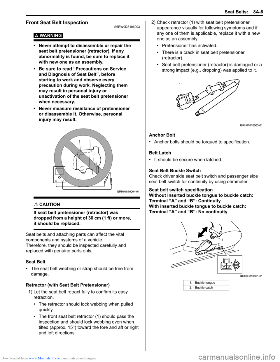
• Never measure resistance of pretensioner
or disassemble it. Otherwise, personal
injury may result.
CAUTION!
If seat belt pretensioner (retractor) was
dropped from a height of 30 cm (1 ft) or more,
it should be replaced.
Seat belts and attaching parts can affect the vital
components and systems of a vehicle.
Therefore, they should be inspected carefully and
replaced with genuine parts only.
Seat Belt
• The seat belt webbing or strap should be free from
damage.
Retractor (with Seat Belt Pretensioner)
1) Let the seat belt retract fully to confirm its easy
retraction.
• The retractor should lock webbing when pulled
quickly.
• The front seat belt retractor (1) should pass the
inspection and should lock webbing even when
tilted (approx. 15°) toward the fore and aft or right
and left directions.2) Check retractor (1) with seat belt pretensioner
appearance visually for following symptoms and if
any one of them is applicable, replace it with a new
one as an assembly.
• Pretensioner has activated.
• There is a crack in seat belt pretensioner
(retractor).
• Seat belt pretensioner (retractor) is damaged or a
strong impact (e.g., dropping) was applied to it.
Anchor Bolt
• Anchor bolts should be torqued to specification.
Belt Latch
• It should be secure when latched.
Seat Belt Buckle Switch
Check driver side seat belt switch and passenger side
seat belt switch for continuity by using ohmmeter.
Seat belt switch specification
Without inserted buckle tongue to buckle catch:
Terminal “A” and “B”: Continuity
With inserted buckle tongue to buckle catch:
Terminal “A” and “B”: No continuityI2RH01810004-01
1. Buckle tongue
2. Buckle catch
I2RH01810005-01
I4RS0B810001-01
Page 1039 of 1556
Downloaded from www.Manualslib.com manuals search engine Seat Belts: 8A-8
Rear Seat Belt Removal and InstallationS6RW0D8106005
WARNING!
Be sure to read “Precautions on Service and
Diagnosis of Seat Belt” before starting to
work and observe every precaution during
work.
Removal
1) Fold rear seats referring to “Folding Rear Seats” in
Owners Manual.
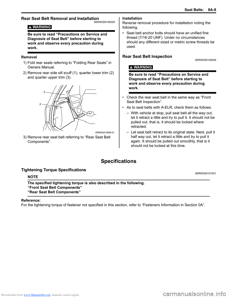
2) Remove rear side sill scuff (1), quarter lower trim (2)
and quarter upper trim (3).
3) Remove rear seat belt referring to “Rear Seat Belt
Components”.Installation
Reverse removal procedure for installation noting the
following.
• Seat belt anchor bolts should have an unified fine
thread (7/16-20 UNF). Under no circumstances
should any different sized or metric screw threads be
used.Rear Seat Belt InspectionS6RW0D8106006
WARNING!
Be sure to read “Precautions on Service and
Diagnosis of Seat Belt” before starting to
work and observe every precaution during
work.
• Check the rear seat belt in the same way as “Front
Seat Belt Inspection”.
• As to seat belts with A-ELR, check them as follows.
– With vehicle at stop, pull seat belt all the way out,
let it retract a little and try to pull it. It should not be
pulled out, that is, it should be locked where
retracted.
– Let seat belt retract to its original state. Next, pull it
half way out, let it retract a little and try to pull it
again. It should be pulled out smoothly, that is it
should not be locked at this time.
Specifications
Tightening Torque SpecificationsS6RW0D8107001
NOTE
The specified tightening torque is also described in the following.
“Front Seat Belt Components”
“Rear Seat Belt Components”
Reference:
For the tightening torque of fastener not specified in this section, refer to “Fasteners Information in Section 0A”.
1 23I5RW0A810005-01
Page 1041 of 1556
Downloaded from www.Manualslib.com manuals search engine Air Bag System: 8B-2
• Never attempt disassembly of SDM.
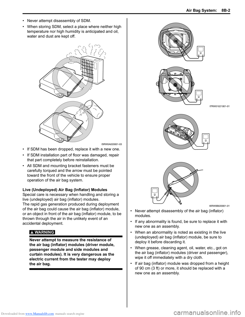
• When storing SDM, select a place where neither high
temperature nor high humidity is anticipated and oil,
water and dust are kept off.
• If SDM has been dropped, replace it with a new one.
• If SDM installation part of floor was damaged, repair
that part completely before reinstallation.
• All SDM and mounting bracket fasteners must be
carefully torqued and the arrow must be pointed
toward the front of the vehicle to ensure proper
operation of the air bag system.
Live (Undeployed) Air Bag (Inflator) Modules
Special care is necessary when handling and storing a
live (undeployed) air bag (inflator) modules.
The rapid gas generation produced during deployment
of the air bag could cause the air bag (inflator) module,
or an object in front of the air bag (inflator) module, to be
thrown through the air in the unlikely event of an
accidental deployment.
WARNING!
Never attempt to measure the resistance of
the air bag (inflator) modules (driver module,
passenger module and side modules and
curtain modules). It is very dangerous as the
electric current from the tester may deploy
the air bag.
• Never attempt disassembly of the air bag (inflator)
modules.
• If any abnormality is found, be sure to replace it with
new one as an assembly.
• When an abnormality is noted as existing in the live
(undeployed) air bag (inflator) module, be sure to
deploy it before discarding it.
• When grease, cleaning agent, oil, water, etc., got on
the air bag (inflator) modules (driver and passenger),
wipe it off immediately with a dry cloth.
• If air bag (inflator) module was dropped from a height
of 90 cm (3 ft) or more, it should be replaced with a
new one as an assembly.
I5RW0A820001-03
I7RW01821001-01
I6RW0B820001-01
Page 1134 of 1556
Downloaded from www.Manualslib.com manuals search engine 8B-95 Air Bag System:
Installation
1) Check that none of the following faulty conditions
exists.
• Bend, scratch, deformity in vehicle body where
SDM is mounted.
• Foreign matter or rust on mating surface of vehicle
body where SDM is mounted.
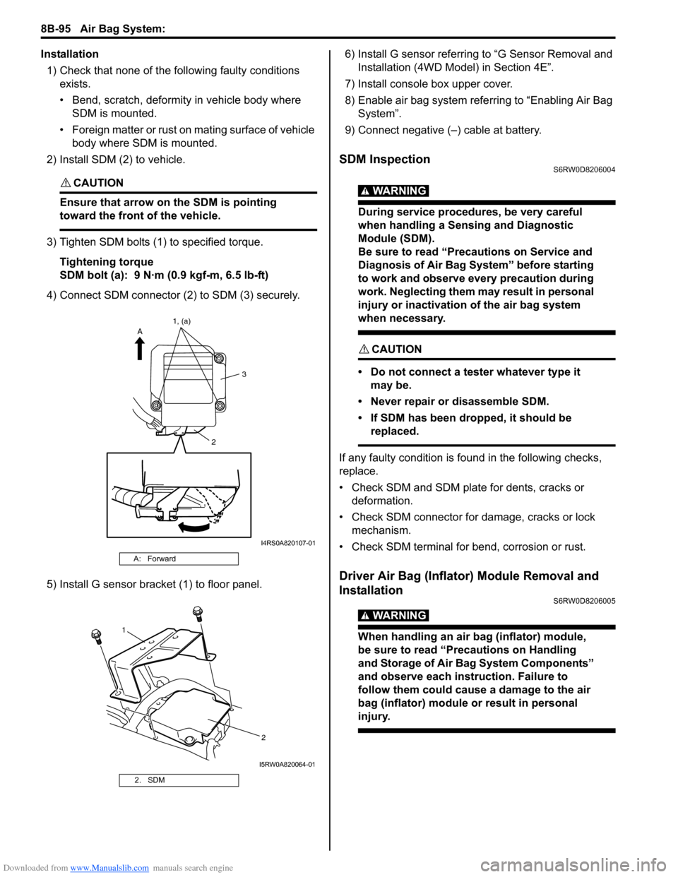
2) Install SDM (2) to vehicle.
CAUTION!
Ensure that arrow on the SDM is pointing
toward the front of the vehicle.
3) Tighten SDM bolts (1) to specified torque.
Tightening torque
SDM bolt (a): 9 N·m (0.9 kgf-m, 6.5 lb-ft)
4) Connect SDM connector (2) to SDM (3) securely.
5) Install G sensor bracket (1) to floor panel.6) Install G sensor referring to “G Sensor Removal and
Installation (4WD Model) in Section 4E”.
7) Install console box upper cover.
8) Enable air bag system referring to “Enabling Air Bag
System”.
9) Connect negative (–) cable at battery.
SDM InspectionS6RW0D8206004
WARNING!
During service procedures, be very careful
when handling a Sensing and Diagnostic
Module (SDM).
Be sure to read “Precautions on Service and
Diagnosis of Air Bag System” before starting
to work and observe every precaution during
work. Neglecting them may result in personal
injury or inactivation of the air bag system
when necessary.
CAUTION!
• Do not connect a tester whatever type it
may be.
• Never repair or disassemble SDM.
• If SDM has been dropped, it should be
replaced.
If any faulty condition is found in the following checks,
replace.
• Check SDM and SDM plate for dents, cracks or
deformation.
• Check SDM connector for damage, cracks or lock
mechanism.
• Check SDM terminal for bend, corrosion or rust.
Driver Air Bag (Inflator) Module Removal and
Installation
S6RW0D8206005
WARNING!
When handling an air bag (inflator) module,
be sure to read “Precautions on Handling
and Storage of Air Bag System Components”
and observe each instruction. Failure to
follow them could cause a damage to the air
bag (inflator) module or result in personal
injury.
A: Forward
2. SDM
23 A1, (a)
I4RS0A820107-01
1
2
I5RW0A820064-01