2006 SUZUKI SX4 warning
[x] Cancel search: warningPage 1455 of 1556
Downloaded from www.Manualslib.com manuals search engine Paint / Coatings: 9L-1
Body, Cab and Accessories
Paint / Coatings
General Description
Anti-Corrosion Treatment ConstructionS6RW0D9C01001
WARNING!
Standard shop practices, particularly eye protection, should be followed during the performance of the
following operations to avoid personal injury.
As rust proof treatment, steel sheets are given corrosion resistance on the interior and/or exterior.
These corrosion resistance steel sheet materials are called one of two-side galvanized steel sheets.
It is for the sake of rust protection that these materials are selected and given a variety of treatments as described
blow.
• Steel sheets are treated with cathodic electro primer which is excellent in corrosion resistance.
• Rust proof wax coatings are applied to door and side sill insides where moisture is liable to stay.
• Vinyl coating is applied to body underside and wheel housing inside.
• Sealer is applied to door hem, engine compartment steel sheet-to-steel sheet joint, and the like portions to prevent
water penetration and resulting in rust occurrence.
In panel replacement or collision damage repair, leaving the relevant area untreated as it is in any operation which
does disturb the rust proof treatment will cause corrosion to that area. Therefore, it is the essential function of any
repair operation to correctly recoat the related surfaces of the relevant area.
All the metal panels are coated with metal conditioners and primer coating during vehicle production. Following the
repair and/or replacement parts installation, every accessible bare metal surface should be cleaned and coated with
rust proof primer. Perform this operation prior to the application of sealer and rust proof wax coating.
Sealer is applied to the specific joints of a vehicle during production. The sealer is intended to prevent dust from
entering the vehicle and serves also as an anticorrosion barrier. The sealer is applied to the door and hood hem areas
and between panels. Correct and reseal the originally sealed joints if damaged. Reseal the attaching joints of a new
replacement panel and reseal the hem area of a replacement door or hood.
Use a quality sealer to seal the flanged joints, overlap joints and seams. The sealer must have flexible characteristics
and paint ability after it’s applied to repair areas.
For the sealer to fill open joints, use caulking material. Select a sealer in conformance with the place and purpose of a
specific use. Observe the manufacturer’s label-stand instructions when using the sealer.
In many cases, repaired places require color painting. When this is required, follow the ordinary techniques specified
for the finish preparation, color painting and undercoating build-up.
Rust proof wax, a penetrative compound, is applied to the metal-to-metal surfaces (door and side sill insides) where it
is difficult to use ordinary undercoating material for coating. Therefore, when selecting the rust proof wax, it may be the
penetrative type.
During the undercoating (vinyl coating) application, care should be taken that sealer is not applied to the engine-
related parts and shock absorber mounting or rotating parts. Following the under coating, make sure that body drain
holes are kept open.
The sequence of the application steps of the anti-corrosion materials are as follows:
1) Clean and prepare the metal surface.
2) Apply primer.
3) Apply sealer (all joints sealed originally).
4) Apply color in areas where color is required such as hem flanges, exposed joints and under body components.
5) Apply anticorrosion compound (penetrative wax).
6) Apply undercoating (rust proof material).
Page 1473 of 1556
Downloaded from www.Manualslib.com manuals search engine Precautions: 10-1
Control Systems
Precautions
Precautions
Precautions for Control SystemsS6RW0DA000001
Air Bag Warning
Refer to “Air Bag Warning in Section 00”.
Precaution of Troubleshooting for CAN
Refer to “Precaution on CAN Troubleshooting in Section 1A”.
Page 1474 of 1556
Downloaded from www.Manualslib.com manuals search engine 10B-1 Body Electrical Control System:
Control Systems
Body Electrical Control System
Precautions
Precautions in Diagnosing TroubleS6RW0DA200001
• Diagnostic information stored in BCM memory can be cleared as well as checked by using SUZUKI scan tool.
Before using scan tool, read its Operator’s (Instruction) Manual carefully to have good understanding as to what
functions are available and how to use it.
• Be sure to read “Precautions for Electrical Circuit Service in Section 00” before inspection and observe what is
written there.
• Communication of ECM, TCM (A/T model), ABS control module, 4WD control module (if equipped), keyless start
control module (if equipped), combination meter and BCM is established by CAN (Controller Area Network). For
detail of CAN communication for BCM, refer to “CAN Communication System Description”. Therefore, handle CAN
communication line with care referring to “Precaution for CAN Communication System in Section 00”.
General Description
BCM General DescriptionS6RW0DA201001
The Body electrical Control Module (BCM) is
incorporated in junction block. Do not attempt removal of
BCM from junction block as it may cause contact failure.
The BCM incorporates relays and controllers which are
used for the following systems and controls them.
• Power door lock (if equipped)
• Keyless entry (if equipped)
• Door lock function of keyless start system (if
equipped)
• Rear wiper
• Combination meter
• Interior light• Warning buzzer
• Rear end door window defogger and door mirror
heater (if equipped)
• Rear end door opener (if equipped)
• Theft deterrent light
Also, the BCM has a function to cause the interior light
and open door warning light in the combination meter to
turn off when any door is left open for longer than 15
minutes to reduce wasteful battery consumption.
In addition, it is possible to check operation of actuator
which is controlled by BCM by using the output test
function of SUZUKI scan tool to operate actuator
simulatively.
CAN Communication System DescriptionS6RW0DA201002
Refer to “CAN Communication System Description in Section 1A” for CAN communication system description.
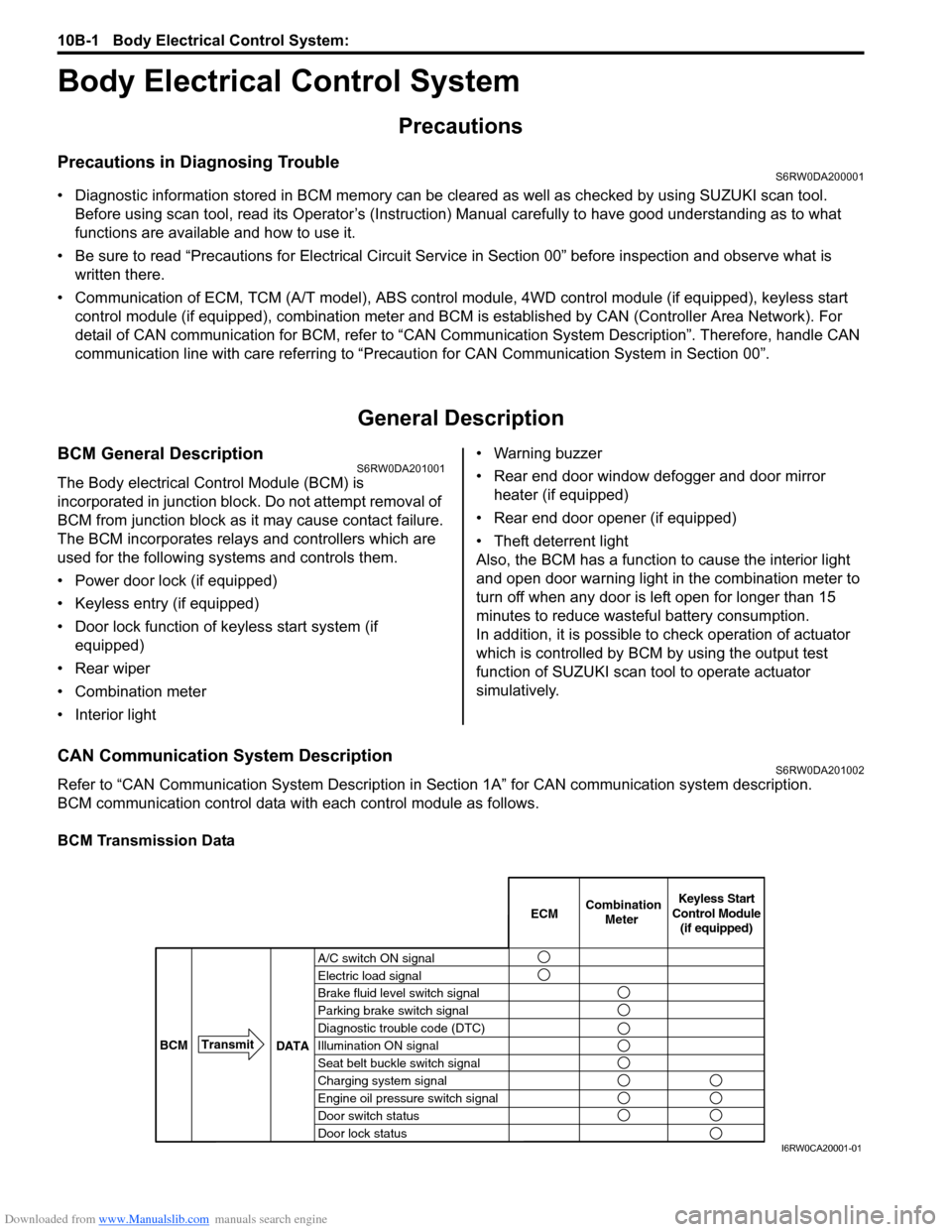
BCM communication control data with each control module as follows.
BCM Transmission Data
A/C switch ON signal
Electric load signal
Brake fluid level switch signal
Parking brake switch signal
Diagnostic trouble code (DTC)
Illumination ON signal
Seat belt buckle switch signal
Charging system signal
Engine oil pressure switch signal
Door switch status
Door lock statusECMKeyless Start
Control Module
(if equipped) Combination
Meter
BCMTransmit
DATA
I6RW0CA20001-01
Page 1475 of 1556
Downloaded from www.Manualslib.com manuals search engine Body Electrical Control System: 10B-2
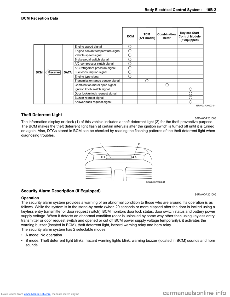
BCM Reception Data
Theft Deterrent LightS6RW0DA201003
The information display or clock (1) of this vehicle includes a theft deterrent light (2) for the theft preventive purpose.
The BCM makes the theft deterrent light flash at certain intervals after the ignition switch is turned off until it is turned
on again. Also, DTCs stored in BCM can be checked by reading the flashing patterns of the theft deterrent light when
diagnosing troubles.
Security Alarm Description (If Equipped)S6RW0DA201005
Operation
The security alarm system provides a warning of an abnormal condition to those who are around. Its operation is as
follows. While the system is in the stand-by mode (when 20 seconds or more elapsed after the door is locked using a
keyless entry transmitter or door request switch), BCM monitors door lock status, door switch status and battery power
supply voltage. When it detects an abnormal condition (door is unlocked by some way other than using keyless entry
transmitter or door request switch and opened or cut off BCM power supply voltage temporarily), it activates the
warning buzzer (located in BCM), theft deterrent light, hazard warning relay and horn relay.
The security alarm system has 2 selectable modes.
• A mode: No operation
• B mode: Theft deterrent light blinks, hazard warning lights blink, warning buzzer (located in BCM) sounds and horn
sounds
Engine speed signal
Vehicle speed signal Engine coolant temperature signal
Brake pedal switch signal
A/C refrigerant pressure signal
Fuel consumption signal A/C compressor clutch signal
Engine type signal
Transmission range sensor signal
Combination meter spec signal
Ignition knob switch signal
Door lock/unlock request signal
Buzzer request signal
Answer back request signal DATA BCM
Receive
Combination
Meter TCM
(A/T model)Keyless Start
Control Module
(if equipped) ECM
I6RW0CA20002-01
12
I5RW0AA20003-01
Page 1476 of 1556
Downloaded from www.Manualslib.com manuals search engine 10B-3 Body Electrical Control System:
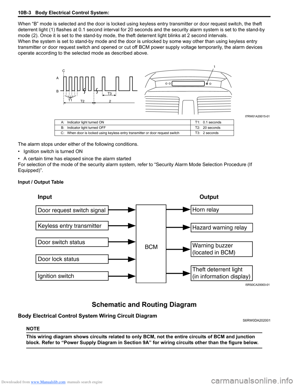
When “B” mode is selected and the door is locked using keyless entry transmitter or door request switch, the theft
deterrent light (1) flashes at 0.1 second interval for 20 seconds and the security alarm system is set to the stand-by
mode (2). Once it is set to the stand-by mode, the theft deterrent light blinks at 2 second intervals.
When the system is set to stand-by mode and the door is unlocked by some way other than using keyless entry
transmitter or door request switch and opened or cut off BCM power supply voltage temporarily, the alarm devices
operate according to the selected mode as described above.
The alarm stops under either of the following conditions.
• Ignition switch is turned ON
• A certain time has elapsed since the alarm started
For selection of the mode of the security alarm system, refer to “Security Alarm Mode Selection Procedure (If
Equipped)”.
Input / Output Table
Schematic and Routing Diagram
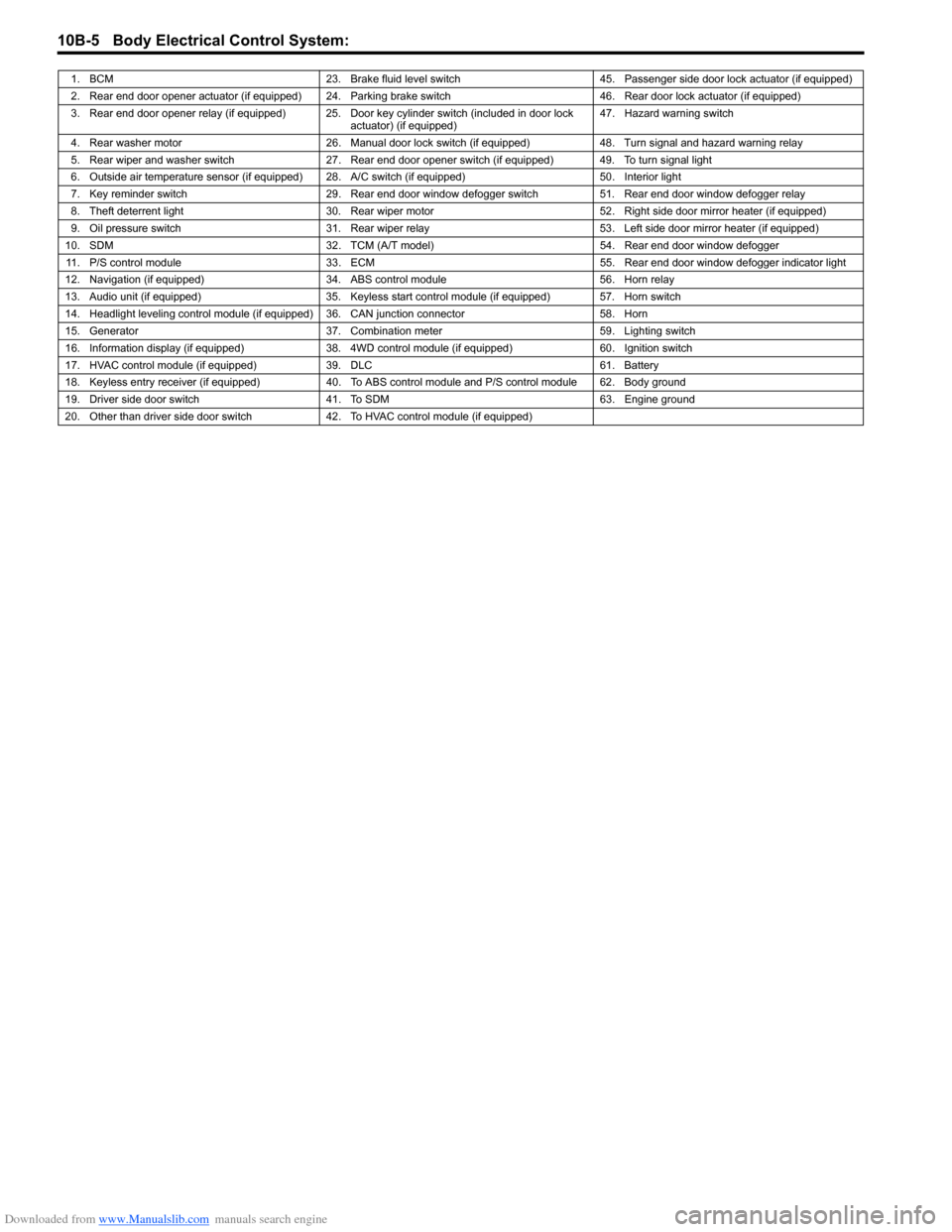
Body Electrical Control System Wiring Circuit DiagramS6RW0DA202001
NOTE
This wiring diagram shows circuits related to only BCM, not the entire circuits of BCM and junction
block. Refer to “Power Supply Diagram in Section 9A” for wiring circuits other than the figure below.
B AT3
T1
T2 2 C
1
I7RW01A20015-01
A: Indicator light turned ON T1: 0.1 seconds
B: Indicator light turned OFF T2: 20 seconds
C: When door is locked using keyless entry transmitter or door request switch T3: 2 seconds
Input Output
Keyless entry transmitter
Door switch status
Door lock statusBCMHorn relay
Theft deterrent light
(in information display)
Warning buzzer
(located in BCM)
Hazard warning relay
Door request switch signal
Ignition switch
I5RS0CA20003-01
Page 1478 of 1556
Downloaded from www.Manualslib.com manuals search engine 10B-5 Body Electrical Control System:
1. BCM 23. Brake fluid level switch 45. Passenger side door lock actuator (if equipped)
2. Rear end door opener actuator (if equipped) 24. Parking brake switch 46. Rear door lock actuator (if equipped)
3. Rear end door opener relay (if equipped) 25. Door key cylinder switch (included in door lock
actuator) (if equipped)47. Hazard warning switch
4. Rear washer motor 26. Manual door lock switch (if equipped) 48. Turn signal and hazard warning relay
5. Rear wiper and washer switch 27. Rear end door opener switch (if equipped) 49. To turn signal light
6. Outside air temperature sensor (if equipped) 28. A/C switch (if equipped) 50. Interior light
7. Key reminder switch 29. Rear end door window defogger switch 51. Rear end door window defogger relay
8. Theft deterrent light 30. Rear wiper motor 52. Right side door mirror heater (if equipped)
9. Oil pressure switch 31. Rear wiper relay 53. Left side door mirror heater (if equipped)
10. SDM 32. TCM (A/T model) 54. Rear end door window defogger
11. P/S control module 33. ECM 55. Rear end door window defogger indicator light
12. Navigation (if equipped) 34. ABS control module 56. Horn relay
13. Audio unit (if equipped) 35. Keyless start control module (if equipped) 57. Horn switch
14. Headlight leveling control module (if equipped) 36. CAN junction connector 58. Horn
15. Generator 37. Combination meter 59. Lighting switch
16. Information display (if equipped) 38. 4WD control module (if equipped) 60. Ignition switch
17. HVAC control module (if equipped) 39. DLC 61. Battery
18. Keyless entry receiver (if equipped) 40. To ABS control module and P/S control module 62. Body ground
19. Driver side door switch 41. To SDM 63. Engine ground
20. Other than driver side door switch 42. To HVAC control module (if equipped)
Page 1479 of 1556
Downloaded from www.Manualslib.com manuals search engine Body Electrical Control System: 10B-6
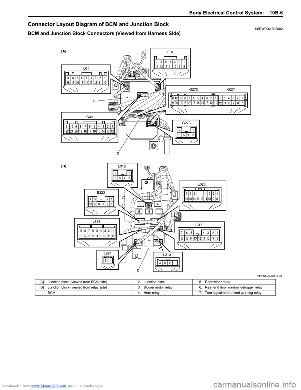
Connector Layout Diagram of BCM and Junction BlockS6RW0DA202002
BCM and Junction Block Connectors (Viewed from Harness Side)
I6RW0CA20004-01
[A]: Junction block (viewed from BCM side) 2. Junction block 5. Rear wiper relay
[B]: Junction block (viewed from relay side) 3. Blower motor relay 6. Rear end door window defogger relay
1. BCM 4. Horn relay 7. Turn signal and hazard warning relay
Page 1480 of 1556
Downloaded from www.Manualslib.com manuals search engine 10B-7 Body Electrical Control System:
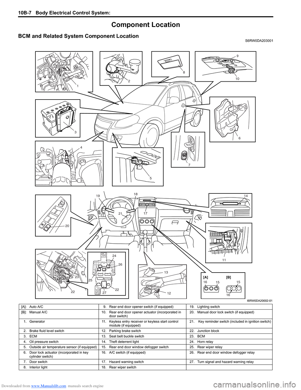
Component Location
BCM and Related System Component LocationS6RW0DA203001
13
12 17 18
21 19
14
24 25
2526
2722 23
22
2476
20
11
5
151615
16 [A] [B]
2
9
10
3
8
4
1
I6RW0DA20002-01
[A]: Auto A/C 9. Rear end door opener switch (if equipped) 19. Lighting switch
[B]: Manual A/C 10. Rear end door opener actuator (incorporated in
door switch)20. Manual door lock switch (if equipped)
1. Generator 11. Keyless entry receiver or keyless start control
module (if equipped)21. Key reminder switch (included in ignition switch)
2. Brake fluid level switch 12. Parking brake switch 22. Junction block
3. ECM 13. Seat belt buckle switch 23. BCM
4. Oil pressure switch 14. Theft deterrent light 24. Horn relay
5. Outside air temperature sensor (if equipped) 15. Rear end door window defogger switch 25. Rear wiper relay
6. Door lock actuator (incorporated in key
cylinder switch)16. A/C switch (if equipped) 26. Rear end door window defogger relay
7. Door switch 17. Hazard warning switch 27. Turn signal and hazard warning relay
8. Interior light 18. Rear wiper switch