2006 SUZUKI SX4 inspection cylinder
[x] Cancel search: inspection cylinderPage 267 of 1556

Downloaded from www.Manualslib.com manuals search engine Aux. Emission Control Devices: 1B-4
EVAP Canister InspectionS6RW0D1206006
WARNING!
DO NOT SUCK nozzles on EVAP canister.
Fuel vapor inside EVAP canister is harmful.
1) Check outside of EVAP canister visually.
2) Disconnect vacuum hoses from EVAP canister.
3) Check that there is no restriction of flow through
purge pipe (1) and air pipe (2) when air is blown (4)
into tank pipe (3).
If any faulty condition is found in this inspection,
replace EVAP canister.
EGR Valve Removal and Installation (If
Equipped)
S6RW0D1206007
Removal
1) Disconnect negative cable at battery.
2) Remove air intake pipe.
3) Remove EGR pipe and gaskets.
4) Disconnect EGR valve connector.
5) Remove EGR valve and gasket from cylinder head.
Installation
Reverse removal procedure noting the following.
• Clean mating surface of valve and cylinder head.
• Use new gaskets.
EGR Valve Inspection (If Equipped)S6RW0D1206008
1) Check resistance between following terminals of
EGR valve (1) in each pair.
If found faulty, replace EGR valve assembly.
EGR valve resistance (A – B, C – B, F – E, D – E
terminal)
20 – 24 Ω
2) Remove carbon from EGR valve gas passage.
CAUTION!
Do not use any sharp-edged tool to remove
carbon.
Be careful not to damage or bend EGR valve
(1), valve seat (3) and rod.
3) Inspect valve (2), valve seat and rod for fault, cracks,
bend or other damage.
If found faulty, replace EGR valve assembly.
4
3 1
2
I6RW0D120003-01
I2RH0B120005-01
I2RH0B120006-01
Page 268 of 1556

Downloaded from www.Manualslib.com manuals search engine 1B-5 Aux. Emission Control Devices:
PCV Hose InspectionS6RW0D1206009
NOTE
Be sure to check that there is no obstruction
in PCV valve or its hoses before checking
IAC throttle valve opening, for obstructed
PCV valve or hose hampers its accurate
adjustment.
Check hoses for connection, leakage, clog and
deterioration.
Replace as necessary.
PCV Valve InspectionS6RW0D1206010
NOTE
Be sure to check that there is no obstruction
in PCV valve or its hoses before checking
IAC throttle valve opening, for obstructed
PCV valve or hose hampers its accurate
adjustment.
1) Detach air cleaner assembly.
2) Disconnect PCV valve from cylinder head cover and
install plug to head cover hole.
3) Install air cleaner assembly temporarily.
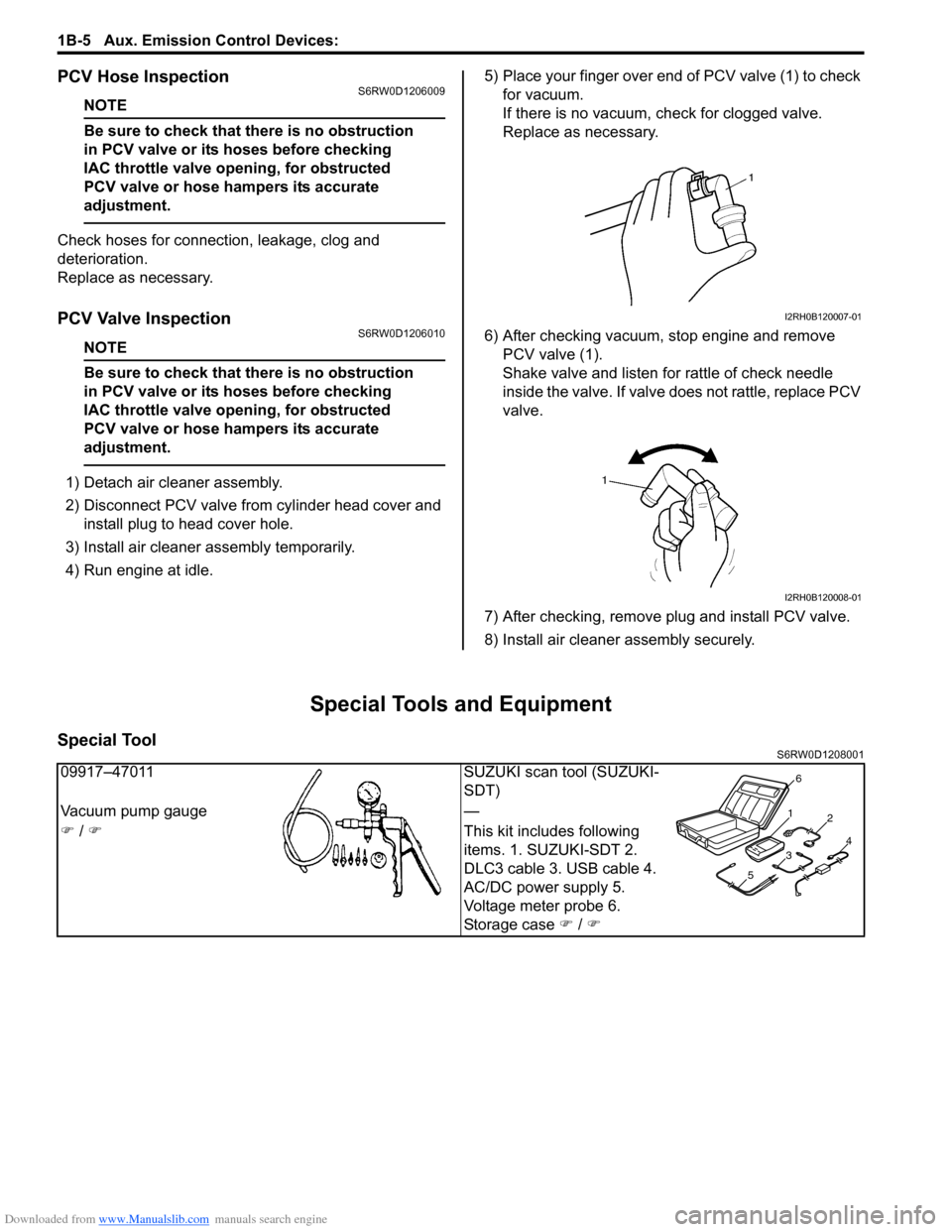
4) Run engine at idle.5) Place your finger over end of PCV valve (1) to check
for vacuum.
If there is no vacuum, check for clogged valve.
Replace as necessary.
6) After checking vacuum, stop engine and remove
PCV valve (1).
Shake valve and listen for rattle of check needle
inside the valve. If valve does not rattle, replace PCV
valve.
7) After checking, remove plug and install PCV valve.
8) Install air cleaner assembly securely.
Special Tools and Equipment
Special ToolS6RW0D1208001
I2RH0B120007-01
I2RH0B120008-01
09917–47011 SUZUKI scan tool (SUZUKI-
SDT)
Vacuum pump gauge —
�) / �)This kit includes following
items. 1. SUZUKI-SDT 2.
DLC3 cable 3. USB cable 4.
AC/DC power supply 5.
Voltage meter probe 6.
Storage case �) / �)
1
2
34
56
Page 277 of 1556

Downloaded from www.Manualslib.com manuals search engine Engine Electrical Devices: 1C-9
Camshaft Position (CMP) Sensor Removal and
Installation
S6RW0D1306012
Removal
1) Disconnect negative cable at battery.
2) Disconnect connector from CMP sensor.
3) Remove camshaft position sensor from timing chain
cover (non-VVT model) or cylinder head (VVT
model).
Installation
1) Install camshaft position sensor to timing chain cover
(non-VVT model) or cylinder head (VVT model).
Tightening torque
CMP sensor bolt (non-VVT model) (a): 10 N·m (
1.0 kgf-m, 7.5 lb-ft)
CMP sensor bolt (VVT model) (b): 11 N·m (1.1
kgf-m, 8.0 lb-ft)
2) Connect connector to CMP sensor securely.
3) Connect negative cable to battery.
Camshaft Position (CMP) Sensor InspectionS6RW0D1306013
Visual check
• Check that O-ring is free from damage.
• Check that end face of sensor and signal rotor tooth
are free from any metal particles and damage.
[A]: Non-VVT model [B]: VVT model
I6RW0D130002-02
I4RS0B130015-01
Page 278 of 1556

Downloaded from www.Manualslib.com manuals search engine 1C-10 Engine Electrical Devices:
Performance check
1) Remove metal particles on end face of CMP sensor,
if any.
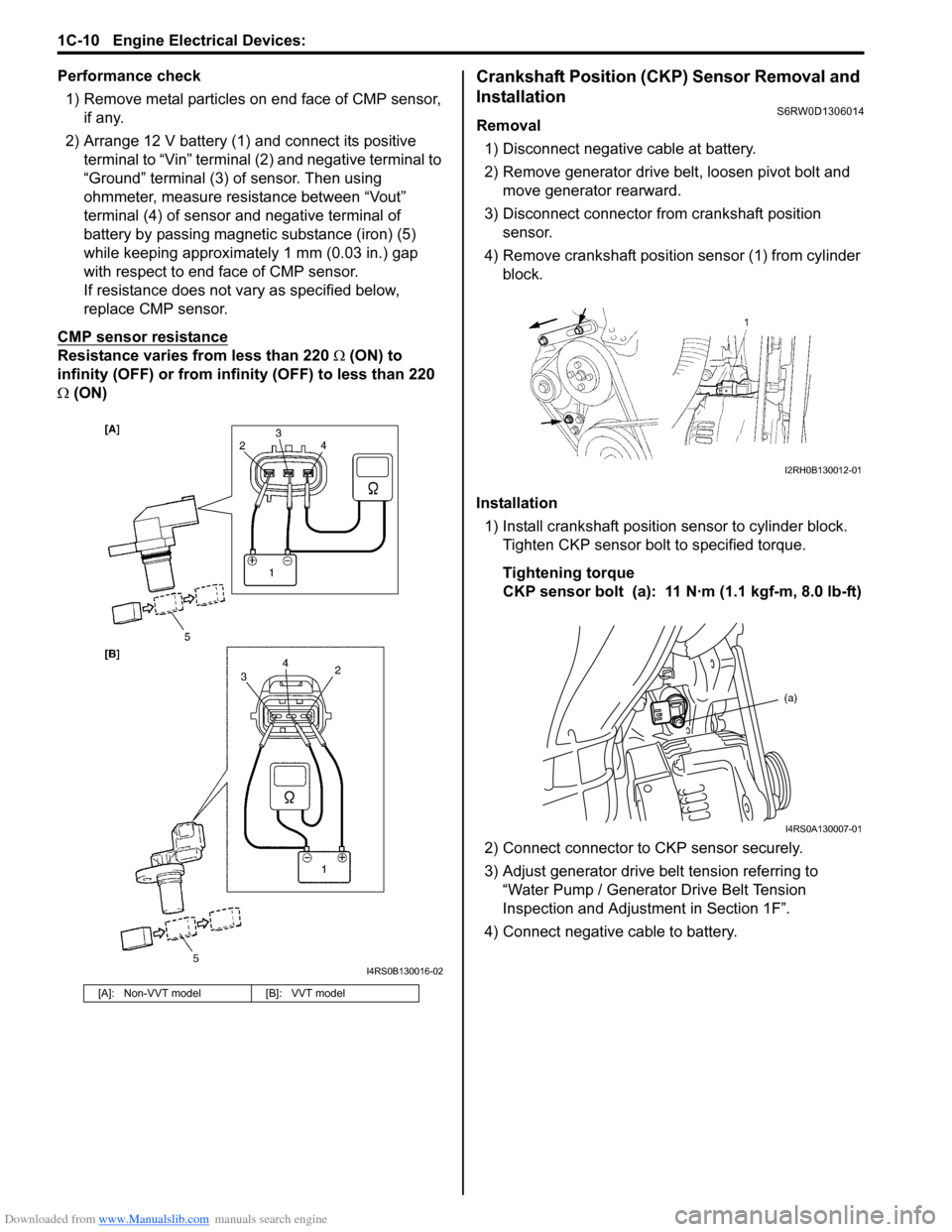
2) Arrange 12 V battery (1) and connect its positive
terminal to “Vin” terminal (2) and negative terminal to
“Ground” terminal (3) of sensor. Then using
ohmmeter, measure resistance between “Vout”
terminal (4) of sensor and negative terminal of
battery by passing magnetic substance (iron) (5)
while keeping approximately 1 mm (0.03 in.) gap
with respect to end face of CMP sensor.
If resistance does not vary as specified below,
replace CMP sensor.
CMP sensor resistance
Resistance varies from less than 220 Ω (ON) to
infinity (OFF) or from infinity (OFF) to less than 220
Ω (ON)
Crankshaft Position (CKP) Sensor Removal and
Installation
S6RW0D1306014
Removal
1) Disconnect negative cable at battery.
2) Remove generator drive belt, loosen pivot bolt and
move generator rearward.
3) Disconnect connector from crankshaft position
sensor.
4) Remove crankshaft position sensor (1) from cylinder
block.
Installation
1) Install crankshaft position sensor to cylinder block.
Tighten CKP sensor bolt to specified torque.
Tightening torque
CKP sensor bolt (a): 11 N·m (1.1 kgf-m, 8.0 lb-ft)
2) Connect connector to CKP sensor securely.
3) Adjust generator drive belt tension referring to
“Water Pump / Generator Drive Belt Tension
Inspection and Adjustment in Section 1F”.
4) Connect negative cable to battery.
[A]: Non-VVT model [B]: VVT model
I4RS0B130016-02
I2RH0B130012-01
(a)
I4RS0A130007-01
Page 279 of 1556

Downloaded from www.Manualslib.com manuals search engine Engine Electrical Devices: 1C-11
Crankshaft Position (CKP) Sensor InspectionS6RW0D1306015
Visual check
• Check that O-ring is free from damage.
• Check that end face of sensor and signal pulley tooth
are free from any metal particles and damage.
Performance check
1) Remove metal particles on end face of CKP sensor,
if any.
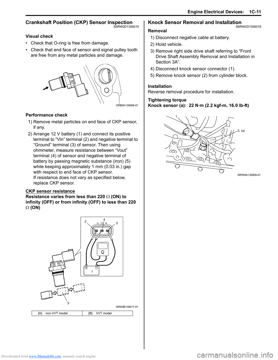
2) Arrange 12 V battery (1) and connect its positive
terminal to “Vin” terminal (2) and negative terminal to
“Ground” terminal (3) of sensor. Then using
ohmmeter, measure resistance between “Vout”
terminal (4) of sensor and negative terminal of
battery by passing magnetic substance (iron) (5)
while keeping approximately 1 mm (0.03 in.) gap
with respect to end face of CKP sensor.
If resistance does not vary as specified below,
replace CKP sensor.
CKP sensor resistance
Resistance varies from less than 220 Ω (ON) to
infinity (OFF) or from infinity (OFF) to less than 220
Ω (ON)
Knock Sensor Removal and InstallationS6RW0D1306016
Removal
1) Disconnect negative cable at battery.
2) Hoist vehicle.
3) Remove right side drive shaft referring to “Front
Drive Shaft Assembly Removal and Installation in
Section 3A”.
4) Disconnect knock sensor connector (1).
5) Remove knock sensor (2) from cylinder block.
Installation
Reverse removal procedure for installation.
Tightening torque
Knock sensor (a): 22 N·m (2.2 kgf-m, 16.0 lb-ft)
[A]: non-VVT model [B]: VVT model
I3RB0A130006-01
I4RS0B130017-01
1
2, (a)
I5RW0A130009-01
Page 289 of 1556

Downloaded from www.Manualslib.com manuals search engine Engine Mechanical: 1D-7
7) Install air cleaner assembly with air suction hose
referring to “Air Cleaner Assembly Removal and
Installation”.
8) Run engine at specified idle speed and read vacuum
gauge. Vacuum should be within specification.
Vacuum specification (at sea level)
59 – 73 kPa (45 – 55 cmHg, 17.7 – 21.6 in.Hg) at
specified idle speed
9) After checking, disconnect special tool (Vacuum
gauge) from PCV valve.
10) Detach blind cap from PCV valve.
11) Install air cleaner assembly with air suction hose
referring to “Air Cleaner Assembly Removal and
Installation”.
Valve Lash (Clearance) InspectionS6RW0D1404003
1) Remove negative cable at battery.
2) Remove cylinder head cover referring to “Cylinder
Head Cover Removal and Installation”.
3) Remove right side engine under cover, if necessary.
4) Using 17 mm wrench, turn crankshaft pulley (1)
clockwise until cam lobes (2) become perpendicular
to shim faces (3) at valves “1” and “7” as shown in
figure.
5) Check valve lashes with thickness gauge (4)
according to the following procedure.
a) Check valve lashes at valves “1” and “7”.
b) Turn camshafts by 90° (by turning crankshaft
with wrench).
c) Make sure that cam lobes are perpendicular to
shim faces at valves to be checked (in this case,
“3” and “8”), if not, adjust it by turning crankshaft.
Check valve lashes.
d) In the same manner as b) – c), check valve
lashes at valves “4” and “6”.
e) In the same manner as b) – c) again, check
valve lashes at valves “2” and “5”.
If valve lash is out of specification, record valve lash and
adjust it to specification by replacing shim.
Valve clearance specification
When cold (Coolant temperature is 15 – 25 °C (59 –
77 °F)):
• Intake: 0.18 – 0.22 mm (0.007 – 0.009 in.)
• Exhaust: 0.28 – 0.32 mm (0.011 – 0.013 in.)
When hot (Coolant temperature is 60 – 68 °C (140 –
154 °F)):
• Intake: 0.21 – 0.27 mm (0.008 – 0.011 in.)
• Exhaust: 0.30 – 0.36 mm (0.012 – 0.014 in.)Replacement of Shim
1) Close the valve whose shim (2) is to be replaced by
turning crankshaft, then turn tappet (3) till its cut
section (1) faces inside as shown in figure.
I3RM0A140004-01
I2RH0B140006-01
Page 307 of 1556

Downloaded from www.Manualslib.com manuals search engine Engine Mechanical: 1D-25
8) For engine with VVT, install new O-ring (1) to oil
gallery pipes No.2 (2) and No.3 (3).
9) For engine with VVT, install oil gallery pipes No.2
and No.3 to cylinder head (4) and timing chain cover
(5).
Tighten bolts to specified torque.
Tightening torque
Oil gallery pipe No.2 and No.3 bolt (a): 11 N·m (
1.1 kgf-m, 8.0 lb-ft)
10) Install water pump pulley.
11) Install cylinder head cover referring to “Cylinder
Head Cover Removal and Installation”.
12) Install oil pan referring to “Oil Pan and Oil Pump
Strainer Removal and Installation in Section 1E”.
13) Install crankshaft pulley (1). Tighten bolt (2) to
specified torque. To lock crankshaft pulley, use
special tool with it as shown in figure.
Special tool
(A): 09917–68221
Tightening torque
Crankshaft pulley bolt (a): 150 N·m (15.0 kgf-m,
108.5 lb-ft)
14) Install engine assembly to vehicle referring to
“Engine Assembly Removal and Installation”.Timing Chain Cover InspectionS6RW0D1406016
Oil Seal
Check oil seal lip for fault or other damage. Replace as
necessary.
Timing Chain Cover (For Engine with VVT)
Inspect strainer (1) of oil passage for driving intake cam
timing sprocket assembly (VVT actuator).
If clog or foreign matter exists, clean strainer.
(a)
(a)1
2
3
4
5
I3RH0B140027-01
I2RH0B140056-01
1
I3RH0B140028-01
Page 318 of 1556

Downloaded from www.Manualslib.com manuals search engine 1D-36 Engine Mechanical:
Camshaft, Tappet and Shim InspectionS6RW0D1406024
Intake Cam Timing Sprocket Assembly (For engine
with VVT)
Fit intake cam timing sprocket assembly to camshaft (2)
and hold hexagonal section of camshaft by using
spanner or the like.
Check if sprocket (1) is not turned by hand.
If moved, replace intake cam timing sprocket assembly.
Cam Wear
Using a micrometer, measure cam height “a”. If
measured height underruns its limit, replace camshaft.
Cam height “a”
[For engine with VVT]
[For engine without VVT]Camshaft Runout
Set camshaft between two “V” blocks, and measure its
runout by using a dial gauge.
If measured runout exceeds limit, replace camshaft.
Camshaft runout limit
0.10 mm (0.0039 in.)
Camshaft Journal Wear
Check camshaft journals and camshaft housings for
pitting, scratches, wear or damage.
If any malcondition is found, replace camshaft or cylinder
head with housing. Never replace cylinder head without
replacing housings.
Check clearance by using gauging plastic. Checking
procedure is as follows.
1) Clean housings and camshaft journals.
2) Remove all tappets with shims.
3) Install camshafts to cylinder head.
4) Place a piece of gauging plastic to full width of
journal of camshaft (parallel to camshaft).
5) Install camshaft housing. Cam height Standard Limit
Intake cam44.929 – 45.089 mm
(1.769 – 1.775 in.)44.80 mm
(1.764 in.)
Exhaust cam44.399 – 44.559 mm
(1.748 – 1.754 in.)44.28 mm
(1.743 in.)
Cam height Standard Limit
Intake cam44.919 – 45.079 mm
(1.768 – 1.775 in.)44.80 mm
(1.764 in.)
Exhaust cam44.399 – 44.559 mm
(1.748 – 1.754 in.)44.28 mm
(1.743 in.)
2 1
I3RH0B140043-01
I2RH0B140080-01
I2RH0B140081-01
I2RH0B140082-01