2006 SUZUKI SX4 dome
[x] Cancel search: domePage 1062 of 1556
Downloaded from www.Manualslib.com manuals search engine 8B-23 Air Bag System:
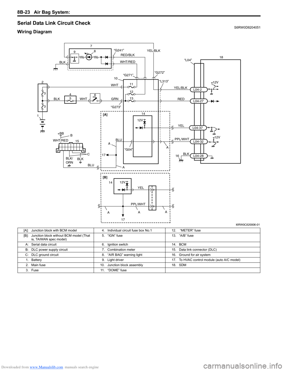
Serial Data Link Circuit CheckS6RW0D8204051
Wiring Diagram
1
2
3
3
18
12V
RED 7
14 9
10
“L313”
“G273”
YEL/BLKL04-2
L04-27 “L04”
PPL/WHT
“G04”L04-3212V
8
GRN
15
+BB
56WHTWHT
4
BLUBLU
BLK
16
11
12
“G241”
13
BLK
L04-28
RED/BLK
WHT/REDYEL/BLK
BLK“G271”
“G272”
WHT/RED
BLK/
ORNBLK
B
C
A A
A
17
[A]
A
[B]
12V
PPL/WHTYEL14
17A
A
YELL04-37
12V
I6RW0C820006-01
[A]: Junction block with BCM model 4. Individual circuit fuse box No.1 12. “METER” fuse
[B]: Junction block without BCM model (That
is, TAIWAN spec model)5. “IGN” fuse 13. “A/B” fuse
A: Serial data circuit 6. Ignition switch 14. BCM
B: DLC power supply circuit 7. Combination meter 15. Data link connector (DLC)
C: DLC ground circuit 8. “AIR BAG” warning light 16. Ground for air system
1. Battery 9. Light driver 17. To HVAC control module (auto A/C model)
2. Main fuse 10. Junction block assembly 18. SDM
3. Fuse 11. “DOME” fuse
Page 1124 of 1556
Downloaded from www.Manualslib.com manuals search engine 8B-85 Air Bag System:
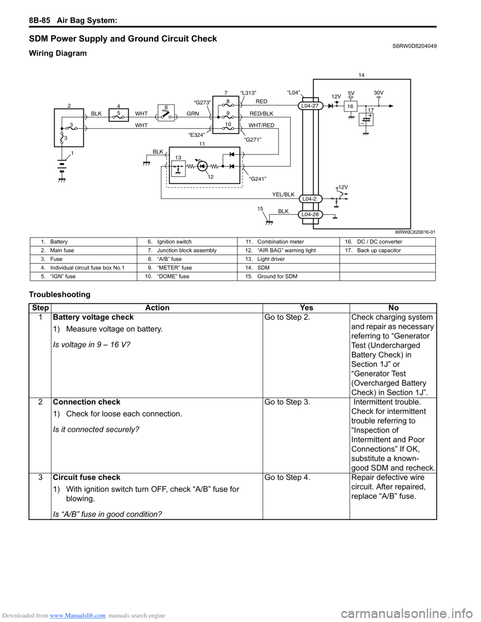
SDM Power Supply and Ground Circuit CheckS6RW0D8204049
Wiring Diagram
Troubleshooting
“L04”14
5
9RED
RED/BLK GRN
YEL/BLK
BLK
8 7
11
12
15
L04-2
L04-28
L04-27
“G241” “G271” “L313”
13
12V
6
1BLK
WHT WHT
WHT/RED 2
34
310 BLK
“G273”
“E324”16
12V5V30V
17
I6RW0C820016-01
1. Battery 6. Ignition switch 11. Combination meter 16. DC / DC converter
2. Main fuse 7. Junction block assembly 12. “AIR BAG” warning light 17. Back up capacitor
3. Fuse 8. “A/B” fuse 13. Light driver
4. Individual circuit fuse box No.1 9. “METER” fuse 14. SDM
5. “IGN” fuse 10. “DOME” fuse 15. Ground for SDM
Step Action Yes No
1Battery voltage check
1) Measure voltage on battery.
Is voltage in 9 – 16 V?Go to Step 2. Check charging system
and repair as necessary
referring to “Generator
Test (Undercharged
Battery Check) in
Section 1J” or
“Generator Test
(Overcharged Battery
Check) in Section 1J”.
2Connection check
1) Check for loose each connection.
Is it connected securely?Go to Step 3. Intermittent trouble.
Check for intermittent
trouble referring to
“Inspection of
Intermittent and Poor
Connections” If OK,
substitute a known-
good SDM and recheck.
3Circuit fuse check
1) With ignition switch turn OFF, check “A/B” fuse for
blowing.
Is “A/B” fuse in good condition?Go to Step 4. Repair defective wire
circuit. After repaired,
replace “A/B” fuse.
Page 1163 of 1556
Downloaded from www.Manualslib.com manuals search engine Table of Contents 9-iii
Headlight Bulb Replacement (Discharge
Headlight Model) ............................................. 9B-19
Ballast Removal and Installation (Discharge
Headlight Model) ............................................. 9B-19
Igniter Removal and Installation (Discharge
Headlight Model) ............................................. 9B-20
Headlight Aiming Adjustment with Screen ........ 9B-20
Headlight Switch (in Lighting Switch)
Removal and Installation................................. 9B-22
Headlight Switch (in Lighting Switch)
Inspection........................................................ 9B-22
Hazard Warning Switch Removal and
Installation ....................................................... 9B-23
Hazard Warning Switch Inspection ................... 9B-23
Brake Light Switch Inspection ........................... 9B-23
Turn Signal Light Switch (in Lighting Switch)
Removal and Installation................................. 9B-24
Turn Signal Light Switch (in Lighting Switch)
Inspection........................................................ 9B-24
Turn Signal and Hazard Warning Relay
Removal and Installation................................. 9B-24
Turn Signal and Hazard Warning Relay
Inspection........................................................ 9B-25
License Light Assembly Removal and
Installation ....................................................... 9B-25
Front Fog Light Assembly Removal and
Installation (If Equipped) ................................. 9B-26
Front Fog Light Switch Inspection (If
Equipped)........................................................ 9B-26
Front Fog Light Aiming Adjustment with
Screen (If Equipped) ....................................... 9B-26
Rear Fog Light Switch Inspection (If
Equipped)........................................................ 9B-27
Headlight Manual Levering Switch Inspection
(If Equipped) ................................................... 9B-28
Headlight Leveling Actuator Inspection (If
Equipped)........................................................ 9B-28
Height Sensor Removal and Installation (If
Equipped)........................................................ 9B-29
Height Sensor and Its Circuit Inspection (If
Equipped)........................................................ 9B-30
Headlight Leveling Control Module Removal
and Installation (If Equipped) .......................... 9B-30
Initialization of Headlight Auto Leveling
System ............................................................ 9B-30
Auto-On Headlight Sensor Inspection (If
Equipped)........................................................ 9B-31
Illumination Cancel Switch Inspection (If
Equipped)........................................................ 9B-32
Tail Light Relay, Headlight Relay, Front Fog
Light Relay Inspection (If Equipped) ............... 9B-32
Specifications..................................................... 9B-33
Tightening Torque Specifications ...................... 9B-33
Instrumentation / Driver Info. / Horn ...... 9C-1
Precautions........................................................... 9C-1
Precautions in Diagnosing Troubles for
Combination Meter............................................ 9C-1
General Description ............................................. 9C-1
CAN Communication System Description........... 9C-1Auto Volume Control System Description (If
Equipped) ..........................................................9C-3
Schematic and Routing Diagram ........................9C-4
Combination Meter Circuit Diagram ....................9C-4
Component Location ...........................................9C-5
Audio System Component Location ....................9C-5
Diagnostic Information and Procedures ............9C-6
Speedometer and VSS Symptom Diagnosis ......9C-6
Tachometer Symptom Diagnosis ........................9C-6
Engine Coolant Temperature (ECT) Meter
Symptom Diagnosis ..........................................9C-6
Fuel Meter Symptom Diagnosis ..........................9C-6
Low Fuel Warning Light Symptom Diagnosis .....9C-7
Oil Pressure Warning Light Symptom
Diagnosis ..........................................................9C-7
Brake and Parking Brake Warning Light
Symptom Diagnosis ..........................................9C-8
Seat Belt Reminder Light Symptom Diagnosis ....9C-8
A/T Shift Position Indicator Symptom
Diagnosis (A/T Model).......................................9C-8
Charge Warning Light Symptom Diagnosis ........9C-9
Main Beam (High Beam) Indicator Symptom
Diagnosis ..........................................................9C-9
Warning Buzzer Circuit Symptom Diagnosis ......9C-9
Cigarette Lighter Symptom Diagnosis (If
Equipped) ........................................................9C-10
Horn Symptom Diagnosis .................................9C-10
Information Display Symptom Diagnosis (If
Equipped) ........................................................9C-10
Clock System Diagnosis (If Equipped) ..............9C-11
Audio System Symptom Diagnosis (If
Equipped) ........................................................9C-12
Remote Audio Control Switch Symptom
Diagnosis (If Equipped) ...................................9C-13
Navigation Symptom Diagnosis (If Equipped)...9C-13
Repair Instructions ............................................9C-14
Ignition Switch Removal and Installation...........9C-14
Ignition Switch Inspection..................................9C-14
Combination Meter Removal and Installation ...9C-14
Fuel Level Sensor Removal and Installation .....9C-15
Fuel Level Sensor Inspection ............................9C-15
Oil Pressure Switch Removal and Installation ..9C-15
Oil Pressure Switch Inspection .........................9C-15
Engine Coolant Temperature (ECT) Sensor
Inspection ........................................................9C-16
Brake Fluid Level Switch Inspection .................9C-16
Parking Brake Switch Inspection.......................9C-16
Door Switch (Front / Rear Door) Inspection ......9C-16
Rear End Door Switch Inspection .....................9C-16
Outside Air Temperature Sensor Removal
and Installation (If Equipped) ..........................9C-17
Outside Air Temperature Sensor Inspection
(If Equipped)....................................................9C-17
Instrument Panel Removal and Installation.......9C-17
Information Display (Clock) Removal and
Installation .......................................................9C-18
Audio Unit Removal and Installation (If
Equipped) ........................................................9C-19
Page 1206 of 1556

Downloaded from www.Manualslib.com manuals search engine 9A-39 Wiring Systems:
30 A WIPCOMB switch
Windshield washer motor
Windshield wiper motor
Rear wiper relay
DRL controller
10 A IG1 SIGPower steering control module
A/T relay
Brake light switch
15 A A/B A/B SDM
10 A ABSABS control module
G sensor
10 A TAILCOMB switch
DRL controller
15 A STOP Brake light switch
20 A D/L BCM
15 A 4WD 4WD control module
10 A ST SIG Starting motor relay
15 A S/HSeat heater switch (Driver side)
Seat heater switch (Passenger side)
10 A IG2 SIG Blower fan relay
15 A RR FOG COMB switch
15 A DOMEAudio
BCM
COMB meter
DLC
ECM
Interior light
ICM
TCM
Rear interior light
Luggage compartment light
Main switch (Key switch)
Multi information display
KLS ECM
30 A RR DEFRear defogger relay
Mirror motor (R)
Mirror motor (L)
15 A HORN-HAZHorn relay
Flasher relay
BLANK BLANK BLANK
BLANK BLANK BLANK
30 A P/WPower window main switch
Front power window sub switch
Rear power window sub switch (R)
Rear power window sub switch (L) No. Fuse Description on the cover Protected circuit
Page 1208 of 1556
Downloaded from www.Manualslib.com manuals search engine 9A-41 Wiring Systems:
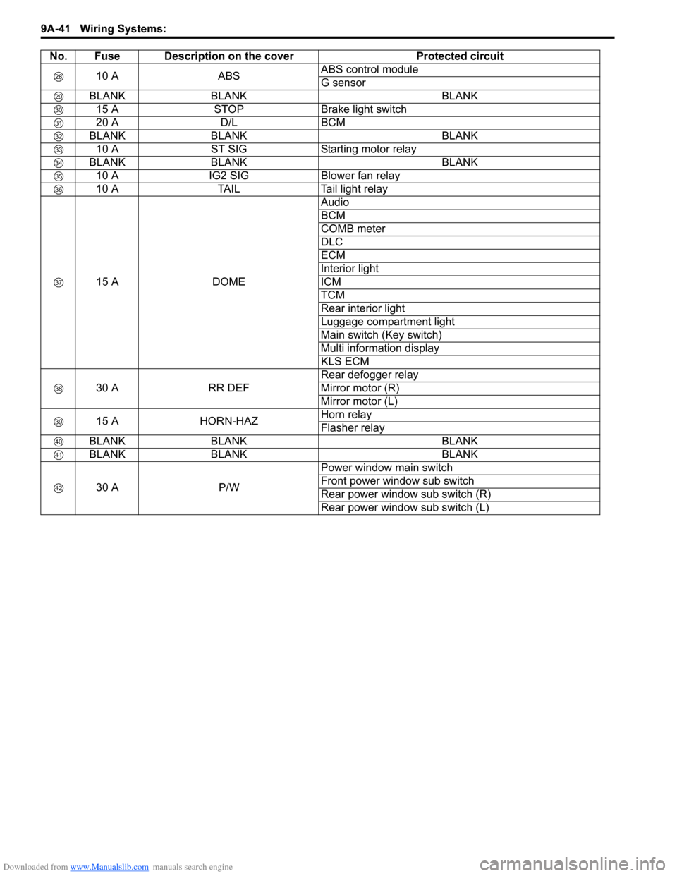
10 A ABSABS control module
G sensor
BLANK BLANK BLANK
15 A STOP Brake light switch
20 A D/L BCM
BLANK BLANK BLANK
10 A ST SIG Starting motor relay
BLANK BLANK BLANK
10 A IG2 SIG Blower fan relay
10 A TAIL Tail light relay
15 A DOMEAudio
BCM
COMB meter
DLC
ECM
Interior light
ICM
TCM
Rear interior light
Luggage compartment light
Main switch (Key switch)
Multi information display
KLS ECM
30 A RR DEFRear defogger relay
Mirror motor (R)
Mirror motor (L)
15 A HORN-HAZHorn relay
Flasher relay
BLANK BLANK BLANK
BLANK BLANK BLANK
30 A P/WPower window main switch
Front power window sub switch
Rear power window sub switch (R)
Rear power window sub switch (L) No. Fuse Description on the cover Protected circuit
Page 1211 of 1556
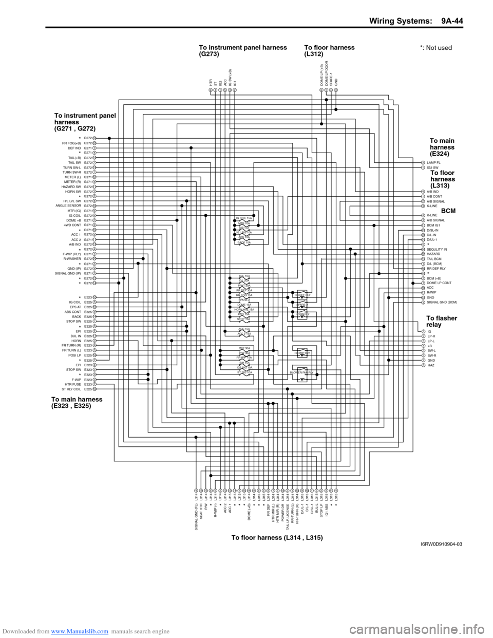
Downloaded from www.Manualslib.com manuals search engine Wiring Systems: 9A-44
1IG2 SW2
6
LAMP FL
1A/B CONT
A/B SIGNAL
K-LINE
K-LINE
A/B SIGNAL
BCM IG1
D/SL-IN
D/L-IN
D/UL-1
SEQULITY IN
HAZARD
TAIL BCM
D/L (BCM)
RR DEF RLY
BCM (+B)
DOME LP CONT
ACC
R/WIP
GND
SIGNAL GND (BCM)4A/B IND
32
98
2511
2423
206
1412
181
215
107
2217
3
1IG
3LP-L2LP-R
4+B5SW-L
7GND6SW-R
8HAZ
DOME LP (+B)543GND SPARE-1 DOME LP DOOR6HTR4ST1IG25ACC3IG SW (+B)2IG1
18107G271415G2727G27219G2721G27212G2719G27111G2723G2722G2728G272166G2716G2725G271810511G27113G2724G2721G27120G2722G2719G2723G27112G27214G272
10E3235E32512E3259E32514E3251E3258E3252E32511E3253E3256E3235E32316E3257E3254E3232E3239E3233E3237E32310E325 DEF IND RR FOG(+B)
*
*
TAIL(+B)
TAIL SW
TURN SW-L
TURN SW-R
METER (L)
METER (R)
HAZARD SW
HORN SW
H/L LVL SW
*
*
MTR (IG) ANGLE SENSOR
IG COIL
DOME +B
4WD CONT
ACC 2
A/B INDACC 1
F-WIP (RLY)
R-WASHER
*
*
* *
*GND (IP)
SIGNAL GND (IP)
*
*
*
IG COIL
EPS AT
ABS CONT
BACK
STOP SW
EPI
BUL IN
HORN
FR TURN (R)
FR TURN (L)
POSI LP
* *
EPI
STOP SW
F-WIP
HTR FUSE
ST RLY COIL
4
L314
15
L314
16
L314
5
L314
9
L314
212
L314
13
L315
14
L315
7
L315
15
L315
14
L314
11
L314
6
L315
5
L315
8
L314
7
L314
6
L314
18
L314
3
L314
L314
110
L314
9
L315
10
L315
1
L315
3
L315
2
L315
8
L315
11
L315
4
L315 SIGNAL GND (FL)
SEAT HTR
P/W
R-WIP (-)* *ACC 2
ACC 1*
*
DOME (+B)
* * *
*
RR DEF
HTR MIR (L)
HTR MIR (R)
TAIL LP, LICENSEPOWER DR
RR-TURN (L)
RR-TURN (R)
BUL-LD/L-1
D/SL-1 D/UL-1
STOP LP
IG1 ABS
*
*
IG COIL 15A
MTR 10A
A/B 15A
IG1 SIG 10A
ABS 10A
BACK 10A
TAIL 10A
D/L 20A
P/WT 20A
RR DEF 30A
RR FOG 15A
SPARE-2
ACC 15A
ACC 2 15A
WIP 30A
P/W 30A
RR WIP 15A
S/H 15A
IG2 SIG 10A
ST SIG 10A HORN HAZ 15A
STOP 15A4WD 15ARR DEF RLY
SPARE-3
HORN RLY
RR WIP RLY
G272 G272
G271
G272
G271
G272 G271
L314
DOME 15A
To instrument panel harness
(G273)*: Not used To floor harness
(L312)
To instrument panel
harness
(G271 , G272)
To main harness
(E323 , E325)
To floor harness (L314 , L315)To main
harness
(E324)
BCM
To flasher
relayTo floor
harness
(L313)
BLOWER FAN RLY
I6RW0D910904-03
Page 1214 of 1556
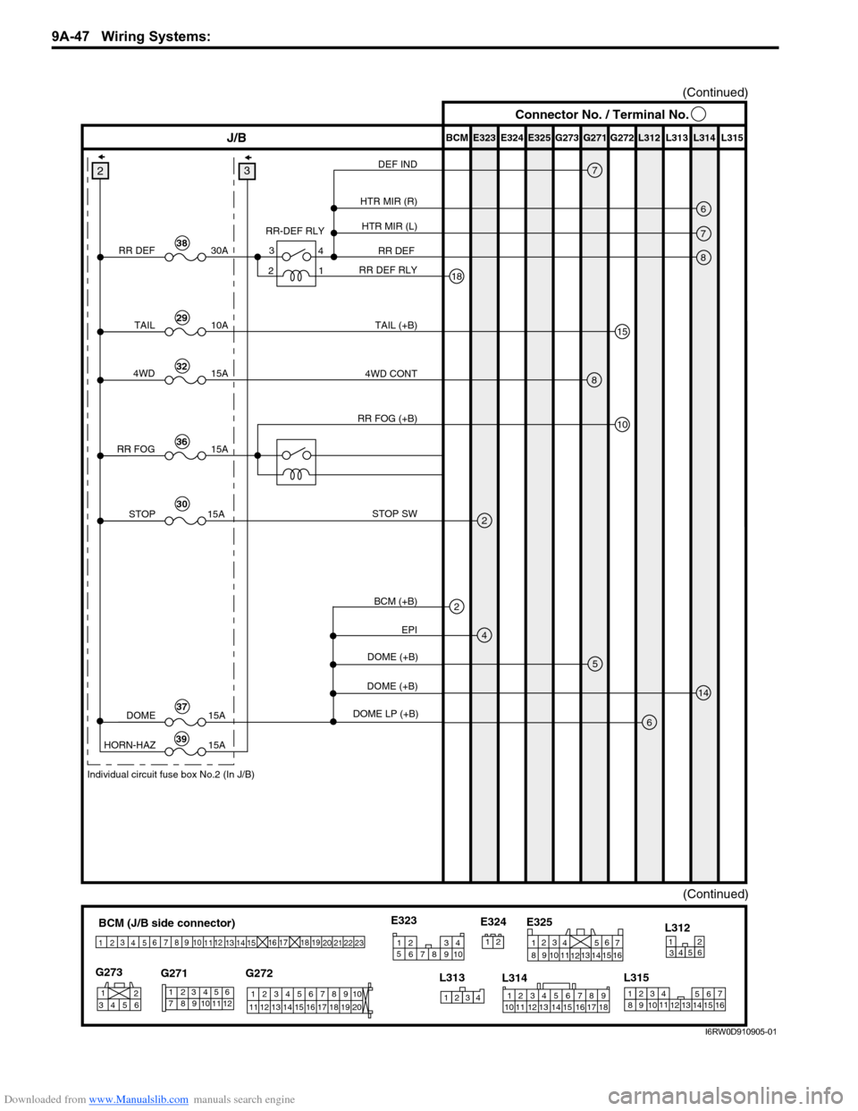
Downloaded from www.Manualslib.com manuals search engine 9A-47 Wiring Systems:
E323 E325E324 BCM G272G271 G273 L312 L313 L314 L315J/B
7
18
8
5
4
14
6
3
(Continued)
DEF IND
RR DEF
6HTR MIR (R)
7HTR MIR (L)
RR DEF RLY RR-DEF RLY
EPI STOP SW
DOME (+B)
DOME (+B)
DOME LP (+B)
15
10
TAIL (+B)
RR DEF
DOME
HORN-HAZ30A
15A
15A
2
38
TAIL10A29
84WD CONT
RR FOG (+B)4WD15A32
2STOP 15A30
37
39
(Continued)
Individual circuit fuse box No.2 (In J/B)
4 3
1
2
RR FOG15A36
Connector No. / Terminal No.
BCM (J/B side connector)
3
4
1
25
15 14 12
13 10
11 9 8 67
17
16182122 19
20
23
1234578 116
12 91034 652 1
G271 G273
G272
10
11 12 13 14 15 16 17 18 19123456789
20
345612L312
23414
3
561214 11
10
157 2 11316 9 8 6
5 4 3
2
1
7
11 10
9 8
15
14 13
1216
L313
L315 E325
2 1
123456789
15 16 17 18 11 10 12 13 14 1
234
5
678 910
E323
L314 E324
2BCM (+B)
I6RW0D910905-01
Page 1216 of 1556
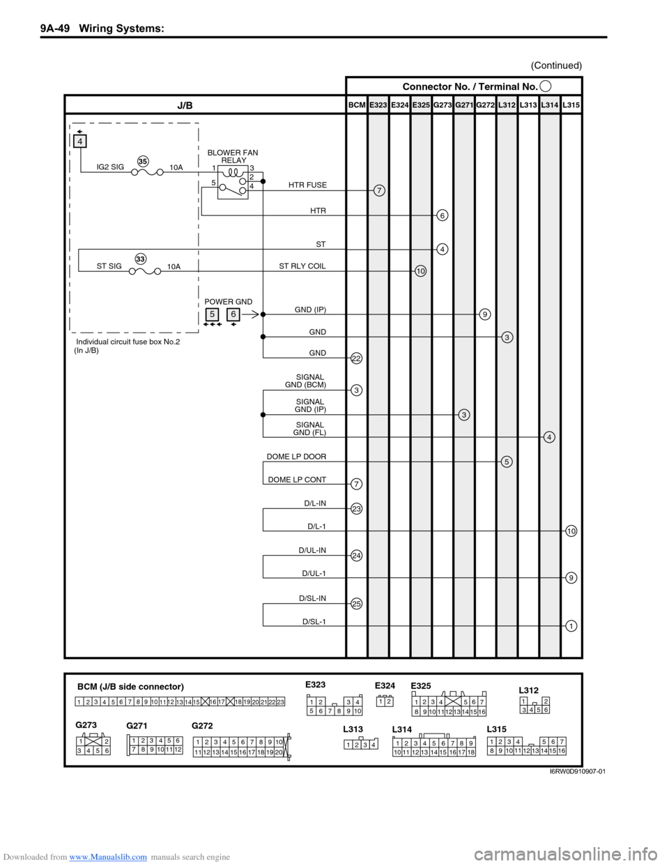
Downloaded from www.Manualslib.com manuals search engine 9A-49 Wiring Systems:
BCM (J/B side connector)
3
4
1
25
15 14 12
13 10
11 9 8 67
17
16182122 19
20
23
1234578 116
12 91034 652 1
G271 G273
G272
10
11 12 13 14 15 16 17 18 19123456789
20
345612L312
23414
3
561214 11
10
157 2 11316 9 8 6
5 4 3
2
1
7
11 10
9 8
15
14 13
1216
L313
L315 E325
2 1
12 34 5 6 78 9
15 16 17 18 11 10 12 13 14 1
234
5
678 910
E323
L314 E324
E323 E325E324 BCM G272G271 G273 L312 L313 L314 L315J/B
9
3
3
4
(Continued)
GND (IP) POWER GND
GND
22GND
SIGNAL
GND (FL)SIGNAL
GND (IP)
5
7DOME LP CONT DOME LP DOOR
23
10D/L-1 D/L-IN
25
1D/SL-1 D/SL-IN
24
9D/UL-1 D/UL-IN
3
SIGNAL
GND (BCM)
4
4
10
ST
ST RLY COIL
ST SIG
10A33
Individual circuit fuse box No.2
(In J/B)
7
6
BLOWER FAN
RELAY
HTR HTR FUSE
IG2 SIG
10A35
3 1
5
4
2
Connector No. / Terminal No.
56
I6RW0D910907-01