2006 SUZUKI SX4 clutch
[x] Cancel search: clutchPage 352 of 1556

Downloaded from www.Manualslib.com manuals search engine 1D-70 Engine Mechanical:
Main Bearing Cap No.1 Bolt
Measure each thread diameter main bearing cap No.1
bolts (1) at “A” on 60 mm (2.36 in.) from seat side of
flange bolt and “B” on 90 mm (3.54 in.) from seat side of
flange bolt by using a micrometer (2).
Calculate difference in diameters (“A” – “B”).
If it exceeds limit, replace with new one.
Main bearing cap No.1 bolt diameter measurement
points
“a”: 60 mm (2.36 in.)
“b”: 90 mm (3.54 in.)
Main bearing cap No.1 bolt diameter difference
Limit (“A” – “B”): 0.2 mm (0.008 in.)
Sensor Plate InspectionS6RW0D1406041
Check sensor plate for crack damage.
If malcondition is found, replace it.
Rear Oil Seal InspectionS6RW0D1406042
Carefully inspect oil seal (1) for wear or damage. If its lip
is worn or damaged, replace it.
Flywheel InspectionS6RW0D1406043
Visual Inspection
• If ring gear is damaged, cracked or worn, replace
flywheel.
• If the surface contacting clutch disc is damaged, or
excessively worn, replace flywheel.
Flywheel Face Runout
Check flywheel face runout with a dial gauge.
If runout exceeds its limit, replace flywheel.
Flywheel face runout
Limit: 0.2 mm (0.0079 in.)
Cylinder Block InspectionS6RW0D1406044
Distortion of Gasketed Surface
Using straightedge and thickness gauge, check
gasketed surface for distortion and, if flatness exceeds
its limit, correct It.
Cylinder block flatness
Limit: 0.03 mm (0.0012 in.)
“A”
“a”
“b”“B”
1
1
2
I2RH0B140145-01
I2RH0B140151-01
I4RS0A140020-01
I2RH01140198-01
I2RH01140199-01
Page 359 of 1556

Downloaded from www.Manualslib.com manuals search engine Engine Lubrication System: 1E-3
8) Start engine and check oil pressure switch for oil
leakage. If oil leakage is found, repair it.
9) Connect oil pressure switch coupler (1).
Repair Instructions
Oil Pan and Oil Pump Strainer ComponentsS6RW0D1506001
I2RH0B150006-01
1
23
4
(a) 5
(b) 6
(b) 8
(b) 9
(b) 7
10
(c)10
(c)
11 12
(d) 13
(d) 1514
I5RH0A150002-02
1. Oil pan:
Apply sealant 99000-31260 to
mating surface.6. Strainer bolt 11. Dowel pin : 35 N⋅m (3.5 kgf-m, 25.5 lb-ft)
2. Strainer 7. Bracket bolt 12. Baffle plate : Tighten 11 N⋅m (1.1 kgf-m, 8.0 lb-
ft) by the specified procedure.
3. O-ring 8. Oil pan nut 13. Baffle plate bolt : 55 N⋅m (5.5 kgf-m, 40.0 lb-ft)
4. Gasket 9. Oil pan bolt
(M6)14. Clutch housing lower plate (M/T
vehicle) or torque converter housing
lower plate (A/T vehicle):11 N⋅m (1.1 kgf-m, 8.0 lb-ft)
5. Drain plug 10. Oil pan bolt
(M10)15. Lower plate bolt : Do not reuse.
Page 360 of 1556

Downloaded from www.Manualslib.com manuals search engine 1E-4 Engine Lubrication System:
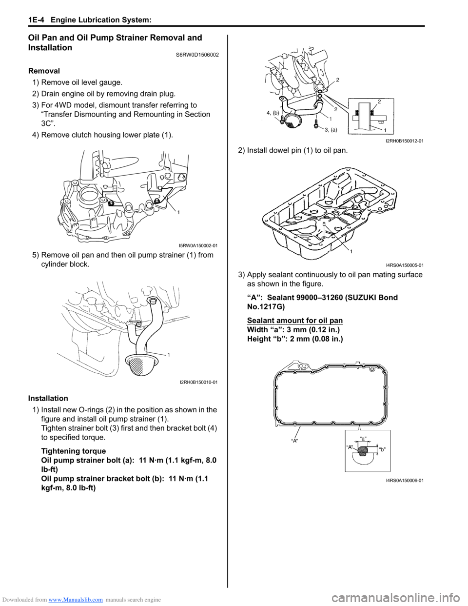
Oil Pan and Oil Pump Strainer Removal and
Installation
S6RW0D1506002
Removal
1) Remove oil level gauge.
2) Drain engine oil by removing drain plug.
3) For 4WD model, dismount transfer referring to
“Transfer Dismounting and Remounting in Section
3C”.
4) Remove clutch housing lower plate (1).
5) Remove oil pan and then oil pump strainer (1) from
cylinder block.
Installation
1) Install new O-rings (2) in the position as shown in the
figure and install oil pump strainer (1).
Tighten strainer bolt (3) first and then bracket bolt (4)
to specified torque.
Tightening torque
Oil pump strainer bolt (a): 11 N·m (1.1 kgf-m, 8.0
lb-ft)
Oil pump strainer bracket bolt (b): 11 N·m (1.1
kgf-m, 8.0 lb-ft)2) Install dowel pin (1) to oil pan.
3) Apply sealant continuously to oil pan mating surface
as shown in the figure.
“A”: Sealant 99000–31260 (SUZUKI Bond
No.1217G)
Sealant amount for oil pan
Width “a”: 3 mm (0.12 in.)
Height “b”: 2 mm (0.08 in.)
1
I5RW0A150002-01
I2RH0B150010-01
I2RH0B150012-01
I4RS0A150005-01
I4RS0A150006-01
Page 361 of 1556

Downloaded from www.Manualslib.com manuals search engine Engine Lubrication System: 1E-5
4) Install oil pan to cylinder block temporarily.
5) Insert dowel pin (1) in hole (2) of oil pan in order to
locate oil pan precisely.
NOTE
Dowel pin is available as a spare part (part
number: 04211–13189).
6) After fitting oil pan to cylinder block, run in securing
bolts and start tightening at the center: move wrench
outward, tightening one bolt at a time. Tighten bolts
and nuts to specified torque.
Tightening torque
Oil pan bolt (M6) (a): 11 N·m (1.1 kgf-m, 8.0 lb-ft)
Oil pan bolt (M10) (c): 55 N·m (5.5 kgf-m, 40.0 lb-
ft)
Oil pan nut (e): 11 N·m (1.1 kgf-m, 8.0 lb-ft)
7) After applying engine oil to drain plug, install new
gasket and drain plug to oil pan.
Tighten drain plug to specified torque.
Tightening torque
Oil pan drain plug (b): 35 N·m (3.5 kgf-m, 25.5 lb-
ft)
8) Tighten transaxle stiffener bolts to specified torque.
Tightening torque
Transaxle stiffener bolt (d): 55 N·m (5.5 kgf-m,
40.0 lb-ft)9) Install clutch housing lower plate (1) and then tighten
clutch housing lower plate bolt to specified torque.
Tightening torque
Clutch housing lower plate bolt (a): 11 N·m (1.1
kgf-m, 8.0 lb-ft)
10) For 4WD model, remount transfer referring to
“Transfer Dismounting and Remounting in Section
3C”.
11) Install oil level gauge.
12) Refill engine with engine oil referring to “Engine Oil
and Filter Change in Section 0B”.
13) Verify that there is no engine oil leakage and exhaust
gas leakage at each connection.
Oil Pan and Oil Pump Strainer CleaningS6RW0D1506003
• Clean sealing surface between oil pan and cylinder
block.
Remove oil, old sealant, and dust from sealing
surface.
• Clean oil pump strainer screen (1).
21I4RS0A150007-01
(a)
(b)
(c)(e)
(d)I4RS0A150008-01
1,(a)
I5RW0A150003-01
I2RH0B150016-01
Page 365 of 1556

Downloaded from www.Manualslib.com manuals search engine Engine Lubrication System: 1E-9
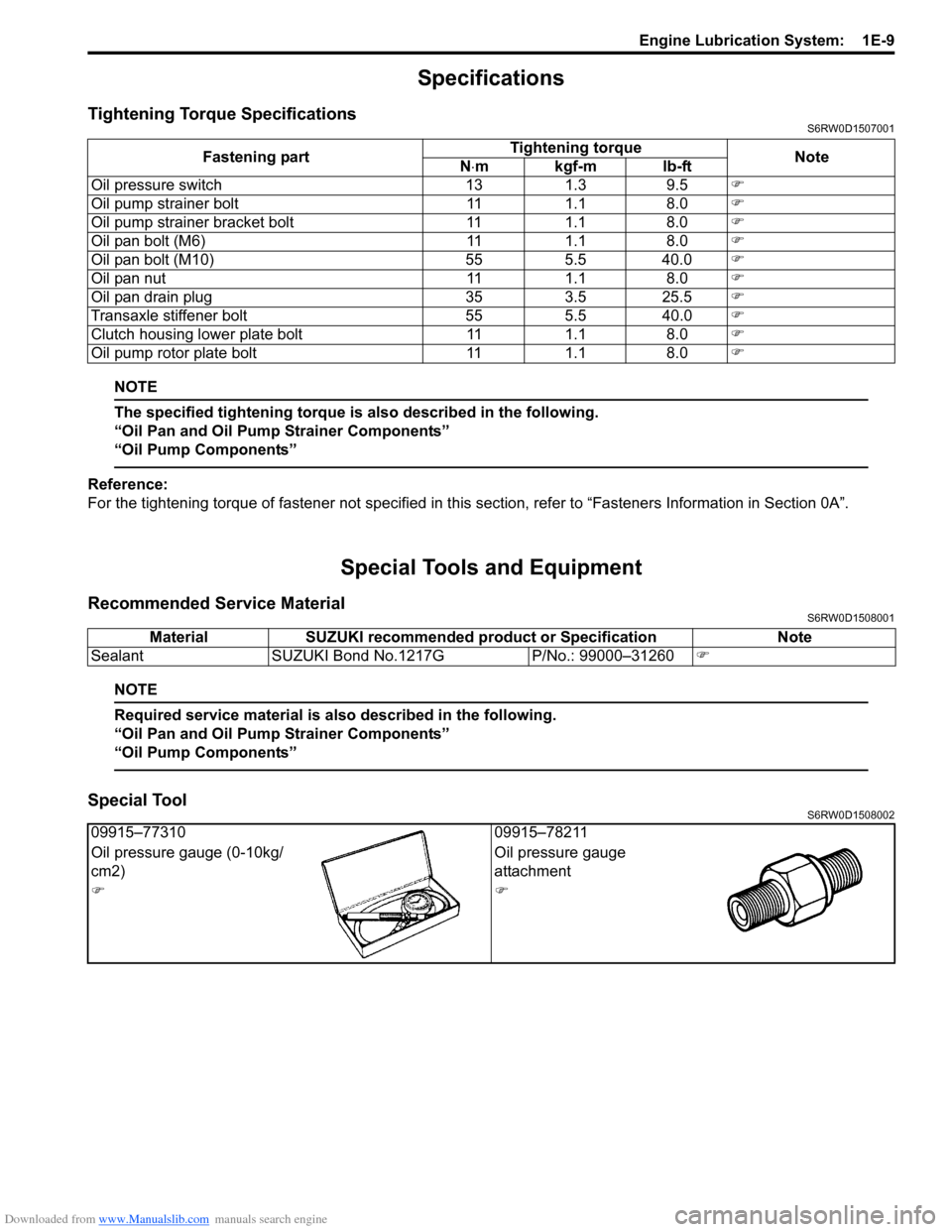
Specifications
Tightening Torque SpecificationsS6RW0D1507001
NOTE
The specified tightening torque is also described in the following.
“Oil Pan and Oil Pump Strainer Components”
“Oil Pump Components”
Reference:
For the tightening torque of fastener not specified in this section, refer to “Fasteners Information in Section 0A”.
Special Tools and Equipment
Recommended Service MaterialS6RW0D1508001
NOTE
Required service material is also described in the following.
“Oil Pan and Oil Pump Strainer Components”
“Oil Pump Components”
Special ToolS6RW0D1508002
Fastening partTightening torque
Note
N⋅mkgf-mlb-ft
Oil pressure switch 13 1.3 9.5�)
Oil pump strainer bolt 11 1.1 8.0�)
Oil pump strainer bracket bolt 11 1.1 8.0�)
Oil pan bolt (M6) 11 1.1 8.0�)
Oil pan bolt (M10) 55 5.5 40.0�)
Oil pan nut 11 1.1 8.0�)
Oil pan drain plug 35 3.5 25.5�)
Transaxle stiffener bolt 55 5.5 40.0�)
Clutch housing lower plate bolt 11 1.1 8.0�)
Oil pump rotor plate bolt 11 1.1 8.0�)
Material SUZUKI recommended product or Specification Note
Sealant SUZUKI Bond No.1217G P/No.: 99000–31260�)
09915–77310 09915–78211
Oil pressure gauge (0-10kg/
cm2)Oil pressure gauge
attachment
�)�)
Page 368 of 1556

Downloaded from www.Manualslib.com manuals search engine 1F-3 Engine Cooling System:
Diagnostic Information and Procedures
Engine Cooling Symptom DiagnosisS6RW0D1604001
Condition Possible cause Correction / Reference Item
Engine overheats
(Radiator fan operates)Loose or broken water pump beltAdjust or replace.
Not enough coolantCheck coolant level and add as necessary.
Faulty thermostatReplace.
Faulty water pumpReplace.
Dirty or bent radiator finsClean or remedy.
Coolant leakage on cooling systemRepair.
Clogged radiatorCheck and replace radiator as necessary.
Faulty radiator capReplace.
Dragging brakesAdjust brake.
Slipping clutchReplace.
Poor charge batteryCheck and replace as necessary.
Poor generation generatorCheck and repair.
ECT sensor faultyCheck and replace as necessary.
Radiator fan motor faultyCheck and replace as necessary.
ECM faultyCheck and replace as necessary.
Wiring or grounding faultyRepair as necessary.
Equipped with too much electric load
part(s)Dismount.
Engine overheats
(Radiator fan does not
operate)Fuse blownCheck fuse of relay/fuse box and check for
short circuit to ground.
Radiator cooling fan relay faultyCheck and replace as necessary.
ECT sensor faultyCheck and replace as necessary.
Radiator cooling fan motor faultyCheck and replace as necessary.
Wiring or grounding faultyRepair as necessary.
ECM faultyCheck and replace as necessary.
Page 406 of 1556

Downloaded from www.Manualslib.com manuals search engine 1I-1 Starting System:
Engine
Starting System
Schematic and Routing Diagram
Cranking System Circuit DiagramS6RW0D1902001
Diagnostic Information and Procedures
Cranking System Symptom DiagnosisS6RW0D1904001
Possible symptoms due to starting system trouble would be as follows:
• Starting motor does not run (or runs slowly)
• Starting motor runs but fails to crank engine
• Abnormal noise is heard
Proper diagnosis must be made to determine exactly where the cause of each trouble lies in battery, wiring harness,
(including starting motor switch), starting motor or engine.
Do not remove motor just because starting motor does not run. Check the following items and narrow down scope of
possible causes.
1) Condition of trouble
2) Tightness of battery terminals (including ground cable connection on engine side) and starting motor terminals
3) Discharge of battery
4) Mounting of starting motor
I4RS0A190001-01
1. Pinion drive lever 6. Magnetic switch contacts 11. Ignition & Starter switch
2. Pinion & Over-running clutch 7. Pull-in coil 12. Battery
3. Magnetic switch 8. Starting motor 13. To ECM
4. Hold-in coil 9. Starting motor control relay
5. Plunger 10. A/T: Transmission range sensor (shift switch)
Page 407 of 1556

Downloaded from www.Manualslib.com manuals search engine Starting System: 1I-2
Condition Possible cause Correction / Reference Item
Motor not running (No
operating sound of
magnetic switch)Transmission range sensor is not in P or
N, or not adjusted (A/T model)Shift in P or N, or adjust sensor. (A/T model)
Battery run downRecharge battery.
Battery voltage too low due to battery
deteriorationReplace battery.
Poor contact in battery terminal
connectionRetighten or replace.
Loose grounding cable connectionRetighten.
Fuse set loose or blown offTighten or replace.
Poor contacting action of ignition switch
and magnetic switchReplace.
Lead wire coupler loose in placeRetighten.
Open-circuit between ignition switch and
magnetic switchRepair.
Open-circuit in pull-in coilReplace magnetic switch.
Brushes are seating poorly or worn
downRepair or replace.
Poor sliding of plunger and/or pinionRepair.
Faulty starting motor control relay“Main Relay, Fuel Pump Relay, Starting Motor
Control Relay, Throttle Actuator Control Relay
and Radiator Cooling Fan Relay Inspection in
Section 1C”.
Faulty ECM and its circuit“Inspection of ECM and Its Circuits in Section
1A”.
Motor not running
(Operating sound of
magnetic switch heard)Battery run downRecharge battery.
Battery voltage too low due to battery
deteriorationReplace battery.
Loose battery cable connectionsRetighten.
Burnt main contact point, or poor
contacting action of magnetic switchReplace magnetic switch.
Brushes are seating poorly or worn
downRepair or replace.
Weakened brush springReplace.
Burnt commutatorReplace armature.
Layer short-circuit of armatureReplace.
Crankshaft rotation obstructedRepair.
Starting motor running
but too slow (small
torque) (If battery and
wiring are satisfactory,
inspect starting motor)Insufficient contact of magnetic switch
main contactsReplace magnetic switch.
Layer short-circuit of armatureReplace.
Disconnected, burnt or worn
commutatorRepair commutator or replace armature.
Worn brushesReplace brush.
Weakened brush springsReplace spring.
Burnt or abnormally worn end bushReplace bush.
Starting motor running,
but not cranking engineWorn pinion tipReplace over-running clutch.
Poor sliding of over-running clutchRepair.
Over-running clutch slippingReplace over-running clutch.
Worn teeth of ring gearReplace flywheel (M/T model) or drive plate (A/
T model).
NoiseAbnormally worn bushReplace bush.
Worn pinion or worn teeth of ring gearReplace over-running clutch, flywheel (M/T
model) or drive plate (A/T model).
Poor sliding of pinion (failure in return
movement)Repair or replace.
Worn internal or planetary gear teethReplace.
Lack of oil in each partLubricate.