2006 SUZUKI SX4 clutch
[x] Cancel search: clutchPage 975 of 1556

Downloaded from www.Manualslib.com manuals search engine Air Conditioning System: Manual Type 7B-35
f) Read stroke of armature plate from dial gauge by
performing step d) and e) repeatedly. (Stroke of
armature plate is clearance between armature
plate and magnet clutch pulley.)
Standard clearance between armature plate
and magnet clutch pulley:
0.3 – 0.5 mm (0.012 – 0.020 in.)
Thermal Switch InspectionS6RW0D7216024
Measured thermal switch for resistance at 20 °C (68 °F)
Thermal switch resistance
Standard: 50 mΩ (DC 16 V, 5A at 20 °C (68 °F))
Thermal Switch Removal and InstallationS6RW0D7216025
Removal
1) Remove compressor from engine referring to
“Compressor Assembly Removal and Installation”.
2) Disconnect thermal switch connector.
3) Remove magnet clutch lead wire clamp.
4) Remove thermal switch (1) from compressor using
flat head (2).
Installation
Reverse removal procedure noting the following
instructions.
• Apply silicon sealant to contact face (2) of thermal
switch (1).
“A”: Silicon sealant 99000–34220 (SUZUKI
SILICON SEALANT KE-347W (100g))
• Install compressor to vehicle referring to “Compressor
Assembly Removal and Installation”.
• Evacuate and charge the A/C system referring to
“Evacuation” and “Charge” in “Operation Procedure
for Refrigerant Charge”.
213
I4RS0A720046-01
I7RW01721024-01
21
I5RS0C721011-01
3
2, “A”1
I5RS0C721012-02
Page 987 of 1556

Downloaded from www.Manualslib.com manuals search engine Air Conditioning System: Automatic Type 7B-47
A/C System Symptom DiagnosisS6RW0D7224002
Condition Possible cause Correction / Reference Item
No cool air comes out (A/
C system does not
operate)No refrigerantPerform recovery, evacuation and charge
referring to “Operation Procedure for
Refrigerant Charge”.
Fuse blownCheck related fuses, and then check for short
circuit to ground.
A/C switch faultyCheck A/C switch referring to “Inspection of
HVAC Control Module and Its Circuit”.
Evaporator temperature sensor faultyCheck evaporator temperature sensor
referring to “Evaporator Temperature Sensor
Inspection”.
A/C refrigerant pressure sensor faultyCheck A/C refrigerant pressure sensor
referring to “A/C Refrigerant Pressure Sensor
and Its Circuit Inspection”.
Wiring or grounding faultyRepair as necessary.
ECM faultyCheck ECM referring to “A/C System
Inspection at ECM”.
HVAC control module faultyCheck HVAC control module referring to
“Inspection of HVAC Control Module and Its
Circuit”.
Magnet clutch faultyCheck magnet clutch referring to “Magnet
Clutch Inspection”.
Compressor drive belt loosened or
brokenAdjust or replace drive belt.
Compressor faultyCheck compressor.
Compressor relay faultyCheck compressor relay referring to “A/C
System Relay Inspection”.
BCM faultyCheck BCM referring to “Inspection of BCM
and Its Circuits in Section 10B”.
No cool air comes out
(radiator cooling fan
motor does not operate)Fuse blownCheck related fuses, and then check for short
circuit to ground.
Wiring or grounding faultyRepair as necessary.
Condenser cooling fan motor relay faultyCheck condenser cooling fan motor relay
referring to “A/C System Relay Inspection”.
Condenser cooling fan motor faultyCheck condenser cooling fan motor referring to
“Condenser Cooling Fan Inspection”.
ECM faultyCheck ECM referring to “A/C System
Inspection at ECM”.
HVAC control module faultyCheck HVAC control module referring to
“Inspection of HVAC Control Module and Its
Circuit”.
No cool air comes out
(blower motor does not
operate)Fuse blownCheck related fuses, and then check for short
circuit to ground.
Blower motor controller faultyCheck blower motor controller referring to
“Blower Motor Controller Inspection”.
HVAC control module faultyCheck HVAC control module referring to
“Inspection of HVAC Control Module and Its
Circuit”.
Wiring or grounding faultyRepair as necessary.
Blower motor faultyCheck blower motor referring to “Blower Motor
Inspection in Section 7A”.
Blower motor relay faultyCheck blower motor relay referring to “Blower
Motor Relay Inspection in Section 7A”.
Page 988 of 1556

Downloaded from www.Manualslib.com manuals search engine 7B-48 Air Conditioning System: Automatic Type
Cool air does not come
out or insufficient cooling
(A/C compressor normal
operation)Insufficient or excessive charge of
refrigerantCheck the amount of refrigerant and system
for leaks.
Condenser cloggedCheck condenser referring to “Condenser
Assembly On-Vehicle Inspection”.
A/C evaporator clogged or frostedCheck A/C evaporator and evaporator
temperature sensor referring to “Evaporator
Inspection” and “Evaporator Temperature
Sensor Inspection”.
Evaporator temperature sensor faultyCheck evaporator temperature sensor
referring to “Evaporator Temperature Sensor
Inspection”.
Expansion valve faultyCheck expansion valve referring to “Expansion
Valve Inspection”.
Desiccant cloggedCheck desiccant and cap with filter.
Compressor drive belt loosened or
brokenAdjust or replace drive belt.
Magnet clutch faultyCheck magnet clutch referring to “Magnet
Clutch Inspection”.
Compressor faultyCheck compressor.
Air in A/C systemReplace condenser, and then perform
evacuation and charge referring to “Operation
Procedure for Refrigerant Charge”.
Air leaking from HVAC unit or air ductRepair as necessary.
Heater and ventilation system faultyCheck HVAC unit.
HVAC control module faultyCheck HVAC control module referring to
“Inspection of HVAC Control Module and Its
Circuit”.
Temperature control actuator faultyCheck temperature control actuator referring to
“Temperature Control Actuator and Its Circuit
Inspection”.
Blower motor faultyCheck blower motor referring to “Blower Motor
Inspection in Section 7A”.
Excessive compressor oil in A/C systemDrain excessive compressor oil from A/C
system circuit and compressor.
Cool air does not come
out only intermittentlyWiring connection faultyRepair as necessary.
Expansion valve faultyCheck expansion valve referring to “Expansion
Valve Inspection”.
Excessive moisture in A/C systemReplace condenser, and then perform
evacuation and charge referring to “Operation
Procedure for Refrigerant Charge”.
Magnet clutch faultyCheck magnet clutch referring to “Magnet
Clutch Inspection”.
Excessive amount of refrigerantCheck the amount of refrigerant.
Cool air comes out only at
high speedCondenser cloggedCheck condenser referring to “Condenser
Assembly On-Vehicle Inspection”.
Insufficient charge of refrigerantCheck the amount of refrigerant and system
for leaks.
Air in A/C systemReplace condenser, and then perform
evacuation and charge referring to “Operation
Procedure for Refrigerant Charge”.
Compressor drive belt loosened or
brokenAdjust or replace drive belt.
Compressor faultyCheck compressor.
Cool air does not come
out only at high speedExcessive amount of refrigerantCheck the amount of refrigerant.
A/C evaporator frostedCheck A/C evaporator and evaporator
temperature sensor referring to “Evaporator
Inspection” and “Evaporator Temperature
Sensor Inspection”. Condition Possible cause Correction / Reference Item
Page 996 of 1556

Downloaded from www.Manualslib.com manuals search engine 7B-56 Air Conditioning System: Automatic Type
Scan Tool Data Definitions
TEMP CONT SWITCH: (Temperature control selector
position, Max Cool, °C / °F, Max Hot): This
parameter indicates the selected position of
temperature control selector.
CABIN TEMPERATURE: (In-car temperature, °C, °F):
This parameter indicates the in-car temperature
detected by inside air temperature sensor.OUTSIDE AIR TEMP (Outside air temperature, °C,
°F): This parameter indicates the outside air
temperature detected by outside air temperature
sensor.
EVAPORATOR TEMP (Evaporator temperature, °C,
°F): This parameter indicates the temperature of air
passed through evaporator.
COOLANT TEMP (Engine Coolant Temperature °C,
°F): This parameter indicates the engine coolant
temperature detected by engine coolant temperature
sensor. �) COOLANT TEMP
Ignition switch turned ONEngine coolant temperature is
displayed
�) SUN LOAD Reference value depends on the situation 0 W/m
2 – 1988 W/m2
�)MODE CONT
SWITCHIgnition switch turned ON and air flow selector at
AUTO positionAUTO (Selected position of air flow
selector is displayed)
�) FAN CONT SWITCHIgnition switch turned ON and blower speed selector
at AUTO positionAUTO (Selected position of blower
speed selector is displayed)
�) FAN DESIRED VOLTIgnition switch turned ON and blower speed selector
at HighApprox. 12.0 V
Ignition switch turned ON and blower speed selector
at LowApprox. 4.0 V
�) AIR MIX POS SENIgnition switch turned ON and temperature selector
at maximum cool positionApprox. 0.5 V
Ignition switch turned ON and temperature selector
at maximum hot positionApprox. 4.5 V
�)MODE POS SENSORIgnition switch turned ON and air flow selector at
DEF positionApprox. 4.5 V
Ignition switch turned ON and air flow selector at
VENT positionApprox. 0.5 V
�) A/C CONT SIGA/C switch turned ON, blower speed selector at other
than OFF position with engine runningON
A/C switch turned OFF with engine running OFF
�) BLOWER LOAD SIGIgnition switch turned ON, blower speed selector at
other than OFF positionON
Ignition switch turned ON, blower speed selector at
OFF positionOFF
�) AIR INTAKE MODEIgnition switch turned ON and air intake selector at
fresh air (FRE) positionFRE
Ignition switch turned ON and air intake selector at
recirculation air (REC) positionREC
Ignition switch turned ON, air flow selector and
blower speed selector at AUTO positionAUTO
�) REFRIGERANT
PRESSUREA/C ON (A/C is operating) with engine running at
ambient temperature 30 °C (86 °F)1130 – 1560 kPa (For details, refer to
pressure of high pressure gauge
under “A/C System Performance
Inspection”)
A/C OFF (A/C is not operating) with engine running
at ambient temperature 30 °C (86 °F) and engine
coolant temperature 90 °C (194 °F) – 100 °C (212
°F)600 – 1000 kPa after longer than 10
minute for A/C switch turned off
�) A/C COMP CLUTCHA/C switch turned ON, blower speed selector at other
than OFF position with engine runningON
A/C switch turned OFF with engine running OFF
�) VEHICLE SPEED At stop with ignition switch turned ON 0 km/h (0 mph)
�) ENGINE TYPE Ignition switch turned ON Engine type is displayed.
�) METER SPEC Ignition switch turned ONCombination meter spec is displayed. Scan Tool Data ConditionNormal Condition / Reference
Va l u e
Page 997 of 1556

Downloaded from www.Manualslib.com manuals search engine Air Conditioning System: Automatic Type 7B-57
SUN LOAD (W/m2): This parameter indicates the
amount of sunlight detected by sunload sensor.
MODE CONT SWITCH (Air flow selector position,
AUTO, FACE, B/L, FOOT, D/F, DEF): This
parameter indicates the selected position of air flow
selector.
FAN CONT SWITCH (Blower speed selector, AUTO,
OFF, 1st – 8th): This parameter indicates the
selected position of blower speed selector.
FAN DESIRE VOLT (Fan desired voltage, V): This
parameter indicates the consumption voltage of
blower motor.
AIR MIX POS SENSOR (Temperature control
actuator position sensor, V): This parameter
indicates the input signal from position sensor in
temperature control actuator.
MODE POS SENSOR (Air flow control actuator
position sensor, V): This parameter indicates the
input signal from position sensor in air flow control
actuator.
A/C CONT SIG (A/C control signal, ON, OFF): This
parameter indicates the state of A/C switch.BLOWER LOAD SIG (Blower fan load signal, ON,
OFF): ON: Position of blower speed selector is 1st
position or more.
OFF: Position of blower speed selector is OFF
position.
AIR INTAKE MODE (Air intake selector position,
AUTO, FRE, REC): This parameter indicates the
selected position of air intake selector.
REFRIGERANT PRESSURE (A/C refrigerant absolute
pressure, kPa): This parameter indicates the A/C
refrigerant absolute pressure calculated by ECM
A/C COMP CLUCH (A/C compressor magnet clutch,
ON, OFF): This parameter indicates the state of the
A/C compressor magnet clutch.
VEHICLE SPEED (km/h, mph): This parameter
indicates the vehicle speed calculated by ECM.
ENGINE TYPE (Engine type signal, J20, M16 or
M15): This parameter indicates the engine type
signal transmitted by ECM.
METER SPEC (Combination meter spec signal, EU,
UK, US, Canada, DOM): This parameter indicates
the combination meter spec signal transmitted by
combination meter.
Visual InspectionS6RW0D7224009
Check visually the following parts and systems.
DTC B1502: Inside Air Temperature Sensor Circuit MalfunctionS6RW0D7224010
Wiring DiagramInspection item Correction
• Refrigerant leakage and amount
• A/C pipe or hose disconnection,
looseness and
deterioration
• A/C compressor drive belt looseness and damageRefer to “Compressor Drive Belt Inspection
and Adjustment”.
• Battery fluid level and corrosion
of terminal
• Connectors of electric wire harness disconnection and
friction
• Fuses burning
• Parts installation and damage
• Other parts that can be checked visually
5V
G20
1 2 3 4 5 6 7 8 9 10 11 12 13 14
15 16 17 18 19 20 21 24 23 22 25 26 27 28 29 30
ORNORNPNK/BLKG20-10
21
3 [S]
[G]
G20-24
I7RW01722004-01
[S]: Inside air temperature sensor signal circuit 1. HVAC control module 3. To other sensors
[G]: Inside air temperature sensor ground circuit 2. Inside air temperature sensor
Page 1027 of 1556

Downloaded from www.Manualslib.com manuals search engine Air Conditioning System: Automatic Type 7B-87
Condenser Cooling Fan Relay InspectionS6RW0D7226020
Refer to “A/C System Relay Inspection”.
Condenser Cooling Fan Removal and
Installation
S6RW0D7226021
Refer to “Condenser Cooling Fan Removal and
Installation”.
Condenser Cooling Fan InspectionS6RW0D7226022
Refer to “Condenser Cooling Fan Inspection”.
Condenser Assembly On-Vehicle InspectionS6RW0D7226023
Refer to “Condenser Assembly On-Vehicle Inspection”.
Condenser Assembly Removal and InstallationS6RW0D7226024
Refer to “Condenser Assembly Removal and
Installation”.
Evaporator InspectionS6RW0D7226025
Refer to “Evaporator Inspection”.
Evaporator Temperature Sensor Removal and
Installation
S6RW0D7226026
Refer to “Evaporator Temperature Sensor Removal and
Installation”.
Evaporator Temperature Sensor InspectionS6RW0D7226027
Refer to “Evaporator Temperature Sensor Inspection”.
Expansion Valve Removal and InstallationS6RW0D7226028
Refer to “Expansion Valve Removal and Installation”.
Expansion Valve InspectionS6RW0D7226029
Refer to “Expansion Valve Inspection”.
A/C Refrigerant Pressure Sensor and Its Circuit
Inspection
S6RW0D7226030
Refer to “A/C Refrigerant Pressure Sensor and Its Circuit
Inspection”.
A/C Refrigerant Pressure Sensor Removal and
Installation
S6RW0D7226031
Refer to “A/C Refrigerant Pressure Sensor Removal and
Installation”.
Compressor Relay InspectionS6RW0D7226032
Refer to “A/C System Relay Inspection”.
Compressor Drive Belt Inspection and
Adjustment
S6RW0D7226033
Refer to “Compressor Drive Belt Inspection and
Adjustment”.
Compressor Drive Belt Removal and
Installation
S6RW0D7226034
Refer to “Compressor Drive Belt Removal and
Installation”.
Compressor Assembly Removal and
Installation
S6RW0D7226035
Refer to “Compressor Assembly Removal and
Installation”.
Compressor Assembly ComponentsS6RW0D7226036
Refer to “Compressor Assembly Components”.
Magnet Clutch Removal and InstallationS6RW0D7226037
Refer to “Magnet Clutch Removal and Installation”.
Magnet Clutch InspectionS6RW0D7226038
Refer to “Magnet Clutch Inspection”.
Thermal Switch InspectionS6RW0D7226039
Refer to “Thermal Switch Inspection”.
Thermal Switch Removal and InstallationS6RW0D7226040
Refer to “Thermal Switch Removal and Installation”.
Relief Valve InspectionS6RW0D7226041
Refer to “Relief Valve Inspection”.
Page 1186 of 1556

Downloaded from www.Manualslib.com manuals search engine 9A-19 Wiring Systems:
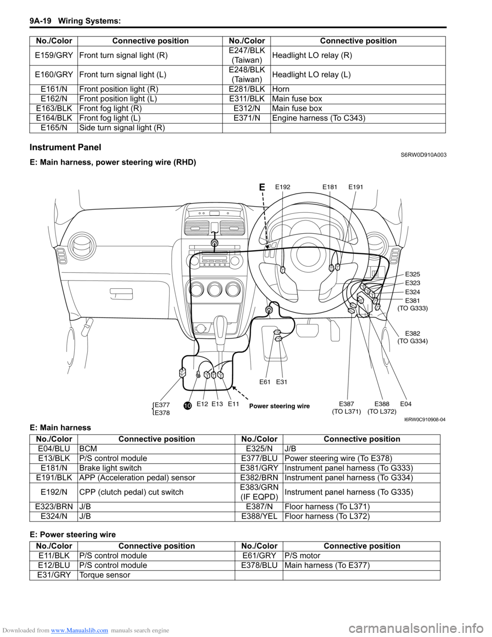
Instrument PanelS6RW0D910A003
E: Main harness, power steering wire (RHD)
E: Main harness
E: Power steering wireE159/GRY Front turn signal light (R)E247/BLK
(Taiwan)Headlight LO relay (R)
E160/GRY Front turn signal light (L)E248/BLK
(Taiwan)Headlight LO relay (L)
E161/N Front position light (R) E281/BLK Horn
E162/N Front position light (L) E311/BLK Main fuse box
E163/BLK Front fog light (R) E312/N Main fuse box
E164/BLK Front fog light (L) E371/N Engine harness (To C343)
E165/N Side turn signal light (R) No./Color Connective position No./Color Connective position
E12E13E11E387
(TO L371)E04E388
(TO L372)
E31E61
E377
E378
E325
E323
E324
E381
(TO G333)
E382
(TO G334)
E191E181E192
10
Power steering wire
E
I6RW0C910908-04
No./Color Connective position No./Color Connective position
E04/BLU BCM E325/N J/B
E13/BLK P/S control module E377/BLU Power steering wire (To E378)
E181/N Brake light switch E381/GRY Instrument panel harness (To G333)
E191/BLK APP (Acceleration pedal) sensor E382/BRN Instrument panel harness (To G334)
E192/N CPP (clutch pedal) cut switchE383/GRN
(IF EQPD)Instrument panel harness (To G335)
E323/BRN J/B E387/N Floor harness (To L371)
E324/N J/B E388/YEL Floor harness (To L372)
No./Color Connective position No./Color Connective position
E11/BLK P/S control module E61/GRY P/S motor
E12/BLU P/S control module E378/BLU Main harness (To E377)
E31/GRY Torque sensor
Page 1475 of 1556

Downloaded from www.Manualslib.com manuals search engine Body Electrical Control System: 10B-2
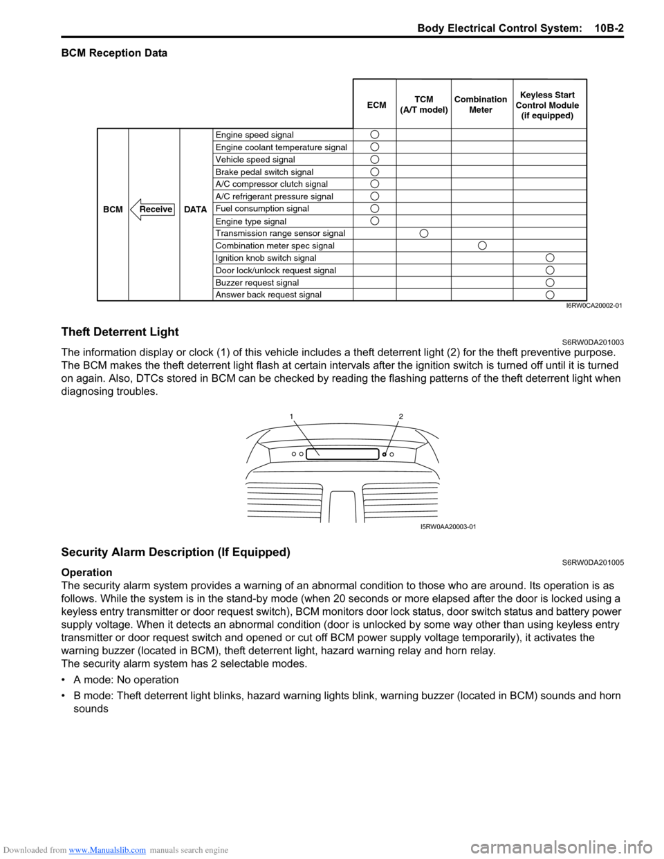
BCM Reception Data
Theft Deterrent LightS6RW0DA201003
The information display or clock (1) of this vehicle includes a theft deterrent light (2) for the theft preventive purpose.
The BCM makes the theft deterrent light flash at certain intervals after the ignition switch is turned off until it is turned
on again. Also, DTCs stored in BCM can be checked by reading the flashing patterns of the theft deterrent light when
diagnosing troubles.
Security Alarm Description (If Equipped)S6RW0DA201005
Operation
The security alarm system provides a warning of an abnormal condition to those who are around. Its operation is as
follows. While the system is in the stand-by mode (when 20 seconds or more elapsed after the door is locked using a
keyless entry transmitter or door request switch), BCM monitors door lock status, door switch status and battery power
supply voltage. When it detects an abnormal condition (door is unlocked by some way other than using keyless entry
transmitter or door request switch and opened or cut off BCM power supply voltage temporarily), it activates the
warning buzzer (located in BCM), theft deterrent light, hazard warning relay and horn relay.
The security alarm system has 2 selectable modes.
• A mode: No operation
• B mode: Theft deterrent light blinks, hazard warning lights blink, warning buzzer (located in BCM) sounds and horn
sounds
Engine speed signal
Vehicle speed signal Engine coolant temperature signal
Brake pedal switch signal
A/C refrigerant pressure signal
Fuel consumption signal A/C compressor clutch signal
Engine type signal
Transmission range sensor signal
Combination meter spec signal
Ignition knob switch signal
Door lock/unlock request signal
Buzzer request signal
Answer back request signal DATA BCM
Receive
Combination
Meter TCM
(A/T model)Keyless Start
Control Module
(if equipped) ECM
I6RW0CA20002-01
12
I5RW0AA20003-01