2006 SUZUKI SX4 clock
[x] Cancel search: clockPage 760 of 1556

Downloaded from www.Manualslib.com manuals search engine 5A-112 Automatic Transmission/Transaxle:
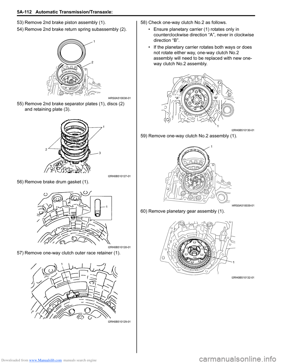
53) Remove 2nd brake piston assembly (1).
54) Remove 2nd brake return spring subassembly (2).
55) Remove 2nd brake separator plates (1), discs (2)
and retaining plate (3).
56) Remove brake drum gasket (1).
57) Remove one-way clutch outer race retainer (1).58) Check one-way clutch No.2 as follows.
• Ensure planetary carrier (1) rotates only in
counterclockwise direction “A”, never in clockwise
direction “B”.
• If the planetary carrier rotates both ways or does
not rotate either way, one-way clutch No.2
assembly will need to be replaced with new one-
way clutch No.2 assembly.
59) Remove one-way clutch No.2 assembly (1).
60) Remove planetary gear assembly (1).
1
2
I4RS0A510038-01
I2RH0B510127-01
I2RH0B510128-01
I2RH0B510129-01
I2RH0B510130-01
1
I4RS0A510039-01
I2RH0B510132-01
Page 796 of 1556

Downloaded from www.Manualslib.com manuals search engine 5A-148 Automatic Transmission/Transaxle:
20) Check for correct installation of planetary gear
assembly as follows.
Measure the distance “a” by using micrometer
caliper (1) and straightedge (2). If measured value is
out of specification, remove planetary gear assembly
and reinstall it properly.
Distance between planetary gear assembly and
mating surface of transaxle case
“a”: More than 49.9 m (1.965 in.)
21) Apply A/T fluid to one-way clutch No.2 assembly (1),
then install it to planetary gear assembly. After that,
ensure that planetary carrier rotates only in
counterclockwise direction “A”, not in clockwise
direction “B”.22) Install one-way clutch outer race retainer (1).
23) Apply A/T fluid to new brake drum gasket (1), then
install it to transaxle case.
24) Apply A/T fluid to 2nd brake retaining plate (1), discs
(2) and separator plates (3), then install them to
transaxle case.
25) Install 2nd brake return spring subassembly (1) to
transaxle case.
“a”
“a”
2
1
I2RH0B510276-01
I2RH0B510277-01
I2RH0B510278-01
I2RH0B510279-01
2
3
1
I2RH0B510280-01
1
I2RH0B510281-01
Page 799 of 1556

Downloaded from www.Manualslib.com manuals search engine Automatic Transmission/Transaxle: 5A-151
39) After applying A/T fluid to intermediate shaft thrust
bearing rear race (3), thrust bearing (2) and front
race (1), install them to forward and reverse clutch
assembly (4).
Bearing race dimension
40) Apply A/T fluid to forward and reverse clutch
assembly (1).
Install forward and reverse clutch assembly while
rotating clockwise and counterclockwise frequently
to fit clutch discs to mating hubs.
NOTE
Before installation, align teeth of forward and
reverse clutch discs to facilitate installation.
41) Check for correct installation of forward and reverse
clutch assembly as follows.
Measure distance “a” by using micrometer caliper (1)
and straightedge (2). If out of specification, remove
forward and reverse clutch assembly, forward clutch
hub, rear planetary sun gear subassembly and one-
way clutch No.1 assembly, and reinstall them
properly.
Distance between forward and reverse clutch
assembly and mating surface of transaxle case
“a”: 27.1 – 29.4 mm (1.067 – 1.157 in.)
42) After applying A/T fluid to O/D and 2nd coast brake
retaining plate (4), separator plate (3), discs (2) and
rear plate (1), install them to transaxle case (5). Front race Rear race
Outside
diameter30.6 mm (1.20 in.) 28.2 mm (1.11 in.)
Thickness 2.0 mm (0.08 in.) 2.0 mm (0.08 in.)
I2RH0B510294-01
I2RH0B510295-01
“a”
“a”
1
2
I2RH0B510296-01
I2RH0B510297-01
Page 802 of 1556

Downloaded from www.Manualslib.com manuals search engine 5A-154 Automatic Transmission/Transaxle:
57) Apply A/T fluid to direct clutch assembly (1).
Install direct clutch assembly while rotating
clockwise and counterclockwise frequently to fit
clutch discs to mating hub.
NOTE
Before installation, align teeth of direct clutch
discs to facilitate installation.
58) Check for correct installation of direct clutch
assembly as follows.
Measure distance “a” by using micrometer caliper (1)
and straightedge (2). If out of specification, remove
direct clutch assembly, direct clutch hub and reinstall
them properly.
Distance between direct clutch assembly and
mating surface of transaxle case
“a”: 10.5 – 11.3 mm (0.413 – 0.445 in.)59) Install oil pump assembly (1) to transaxle case.
Tightening torque
Oil pump assembly bolt (a): 25 N·m (2.5 kgf-m,
18.0 lb-ft)
60) Make sure that input shaft (1) turns smoothly.
I2RH0B510309-01
“a”
“a”
1
2
I2RH0B510310-01
I2RH0B510311-01
I2RH0B510312-01
Page 807 of 1556

Downloaded from www.Manualslib.com manuals search engine Automatic Transmission/Transaxle: 5A-159
83) Install select cable bracket (1).
Tightening torque
Select cable bracket bolt (a): 23 N·m (2.3 kgf-m,
17.0 lb-ft)
84) Apply A/T fluid to O-rings of each sensor and install
input shaft speed sensor (1) and output shaft speed
sensor (VSS) (2).
Tightening torque
Input shaft speed sensor bolt (a): 5.5 N·m (0.55
kgf-m, 4.0 lb-ft)
Output shaft speed sensor (VSS) bolt (b): 13
N·m (1.3 kgf-m, 9.5 lb-ft)
85) Install harness bracket and select cable clamp (3).
Tightening torque
Select cable clamp bolt (c): 13 N·m (1.3 kgf-m,
9.5 lb-ft)
86) Install transmission range sensor to transaxle case,
tighten bolts temporarily at this step.87) Install lock washer (1) and tighten lock nut (2) to
specified torque.
Tightening torque
Transmission range sensor lock nut (a): 7 N·m (
0.7 kgf-m, 5.0 lb-ft)
88) Install manual select lever (1) temporarily at this
step.
89) After shifting manual select lever counterclockwise
fully, select “N” range position by bringing it back 2
notches clockwise.
90) Remove manual select lever (1) at this step.
91) Loosen sensor bolts (4) and align needle direction
shaped on lock washer (2) with “N” reference line (3)
on transmission range sensor by moving sensor in
rotative direction.
92) Tighten sensor bolts to specified torque.
Tightening torque
Transmission range sensor bolt (b): 5.5 N·m (
0.55 kgf-m, 4.0 lb-ft)
93) Bend dents of lock washer (1) in order to prevent
displacement of lock washer.
1
(a)I5RW0C510069-02
(a)13
(c)
2(b)
I2RH0B510330-01
1I2RH0B510331-01
1
2, (a)
I2RH0B510332-01
132
4, (b)
4, (b)
I2RH0B510333-01
I2RH0B510334-01
Page 816 of 1556

Downloaded from www.Manualslib.com manuals search engine 5B-4 Manual Transmission/Transaxle:
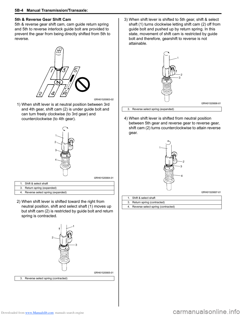
5th & Reverse Gear Shift Cam
5th & reverse gear shift cam, cam guide return spring
and 5th to reverse interlock guide bolt are provided to
prevent the gear from being directly shifted from 5th to
reverse.
1) When shift lever is at neutral position between 3rd
and 4th gear, shift cam (2) is under guide bolt and
can turn freely clockwise (to 3rd gear) and
counterclockwise (to 4th gear).
2) When shift lever is shifted toward the right from
neutral position, shift and select shaft (1) moves up
but shift cam (2) is restricted by guide bolt and return
spring is contracted.3) When shift lever is shifted to 5th gear, shift & select
shaft (1) turns clockwise letting shift cam (2) off from
guide bolt and pushed up by return spring. In this
state, movement of shift cam is restricted by guide
bolt and therefore, gearshift to reverse is not
attainable.
4) When shift lever is shifted from neutral position
between 5th gear and reverse gear to reverse gear,
shift cam (2) turns counterclockwise to attain reverse
gear.
1. Shift & select shaft
3. Return spring (expanded)
4. Reverse select spring (expanded)
3. Reverse select spring (contracted)
I2RH01520003-02
I2RH01520004-01
I2RH01520005-01
3. Reverse select spring (expanded)
1. Shift & select shaft
3. Return spring (contracted)
4. Reverse select spring (contracted)
I2RH01520006-01
I2RH01520007-01
Page 873 of 1556

Downloaded from www.Manualslib.com manuals search engine Steering Wheel and Column: 6B-4
Steering Wheel Removal and InstallationS6RW0D6206002
CAUTION!
Do not turn the contact coil more than
allowable number of turns (about two and a
half turns from the center position clockwise
or counterclockwise respectively) with
steering wheel removed, or coil will break.
Removal
CAUTION!
Do not hammer the end of the shaft.
Hammering it will loosen the plastic shear
pins which maintain the column length and
impair the collapsible design of the column.
1) Disconnect negative (–) cable at battery.
2) Disable air bag system referring to “Disabling Air
Bag System in Section 8B”.
3) Remove driver air bag (inflator) module from
steering wheel. Refer to “Driver Air Bag (Inflator)
Module Removal and Installation in Section 8B”.
4) Disconnect horn connector and audio control switch
connector, if equipped.
5) Remove steering shaft nut and then make alignment
marks (1) on steering wheel and shaft for a guide
during reinstallation.6) Remove steering wheel using special tool.
Special tool
(A): 09944–36011
InstallationCAUTION!
Following 2 Steps (Step 1) and 2)) are
prerequisite for installation of steering wheel.
If steering wheel has been installed without
these 2 Steps, contact coil will break when
steering wheel is turned.
1) Check that vehicle’s front tires are at straight-ahead
position and contact coil is centered. If contact coil is
turned after removing steering wheel, center contact
coil referring to “Centering Contact Coil Cable
Assembly”.
2) Install steering wheel to steering shaft with 2 grooves
(1) on contact coil fitted in 2 lugs (2) in the back of
steering wheel and also aligning marks (3) on
steering wheel and steering shaft.
3) Tighten steering shaft nut (4) to specified torque.
Tightening torque
Steering shaft nut (a): 33 N·m (3.3 kgf-m, 24.0 lb-
ft)
I4RS0A620005-01
(A)
I4RS0A620006-01
I4RS0A620007-01
Page 874 of 1556

Downloaded from www.Manualslib.com manuals search engine 6B-5 Steering Wheel and Column:
4) Connect horn connector and audio control switch
connector, if necessary.
5) Install driver air bag (inflator) module to steering
wheel. Refer to “Driver Air Bag (Inflator) Module
Removal and Installation in Section 8B”.
6) Connect negative (–) cable to battery.
7) Enable air bag system referring to “Enabling Air Bag
System in Section 8B”.
Contact Coil Cable Assembly Removal and
Installation
S6RW0D6206003
CAUTION!
Do not turn contact coil more than allowable
number of turns (about two and a half turns
from the center position clockwise or
counterclockwise respectively), or coil will
break.
Removal
1) Disconnect negative (–) cable at battery.
2) Disable air bag system referring to “Disabling Air
Bag System in Section 8B”.
3) Remove steering wheel from steering column
referring to “Steering Wheel Removal and
Installation”.
4) Remove steering column hole cover.
5) Remove steering column lower cover (2) and upper
cover (1).6) Remove contact coil cable assembly (1) from
steering column.
Installation
1) Check to make sure that vehicle’s front tires are set
at straight-ahead position and then ignition switch is
at LOCK position.
2) Install contact coil cable assembly to steering
column securely.
NOTE
New contact coil cable assembly is supplied
with contact coil set and held at its center
position with a lock pin (1). Remove this lock
pin after installing contact coil cable
assembly to steering column.
2
1
I6RW0B620005-01
1I6RW0B620009-02
I4RS0A620010-01