2006 SUZUKI SX4 check oil
[x] Cancel search: check oilPage 988 of 1556

Downloaded from www.Manualslib.com manuals search engine 7B-48 Air Conditioning System: Automatic Type
Cool air does not come
out or insufficient cooling
(A/C compressor normal
operation)Insufficient or excessive charge of
refrigerantCheck the amount of refrigerant and system
for leaks.
Condenser cloggedCheck condenser referring to “Condenser
Assembly On-Vehicle Inspection”.
A/C evaporator clogged or frostedCheck A/C evaporator and evaporator
temperature sensor referring to “Evaporator
Inspection” and “Evaporator Temperature
Sensor Inspection”.
Evaporator temperature sensor faultyCheck evaporator temperature sensor
referring to “Evaporator Temperature Sensor
Inspection”.
Expansion valve faultyCheck expansion valve referring to “Expansion
Valve Inspection”.
Desiccant cloggedCheck desiccant and cap with filter.
Compressor drive belt loosened or
brokenAdjust or replace drive belt.
Magnet clutch faultyCheck magnet clutch referring to “Magnet
Clutch Inspection”.
Compressor faultyCheck compressor.
Air in A/C systemReplace condenser, and then perform
evacuation and charge referring to “Operation
Procedure for Refrigerant Charge”.
Air leaking from HVAC unit or air ductRepair as necessary.
Heater and ventilation system faultyCheck HVAC unit.
HVAC control module faultyCheck HVAC control module referring to
“Inspection of HVAC Control Module and Its
Circuit”.
Temperature control actuator faultyCheck temperature control actuator referring to
“Temperature Control Actuator and Its Circuit
Inspection”.
Blower motor faultyCheck blower motor referring to “Blower Motor
Inspection in Section 7A”.
Excessive compressor oil in A/C systemDrain excessive compressor oil from A/C
system circuit and compressor.
Cool air does not come
out only intermittentlyWiring connection faultyRepair as necessary.
Expansion valve faultyCheck expansion valve referring to “Expansion
Valve Inspection”.
Excessive moisture in A/C systemReplace condenser, and then perform
evacuation and charge referring to “Operation
Procedure for Refrigerant Charge”.
Magnet clutch faultyCheck magnet clutch referring to “Magnet
Clutch Inspection”.
Excessive amount of refrigerantCheck the amount of refrigerant.
Cool air comes out only at
high speedCondenser cloggedCheck condenser referring to “Condenser
Assembly On-Vehicle Inspection”.
Insufficient charge of refrigerantCheck the amount of refrigerant and system
for leaks.
Air in A/C systemReplace condenser, and then perform
evacuation and charge referring to “Operation
Procedure for Refrigerant Charge”.
Compressor drive belt loosened or
brokenAdjust or replace drive belt.
Compressor faultyCheck compressor.
Cool air does not come
out only at high speedExcessive amount of refrigerantCheck the amount of refrigerant.
A/C evaporator frostedCheck A/C evaporator and evaporator
temperature sensor referring to “Evaporator
Inspection” and “Evaporator Temperature
Sensor Inspection”. Condition Possible cause Correction / Reference Item
Page 1030 of 1556
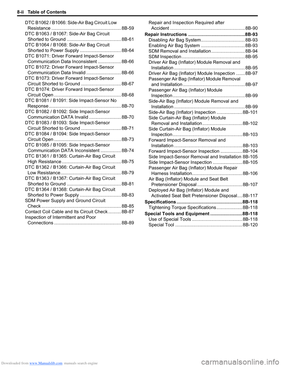
Downloaded from www.Manualslib.com manuals search engine 8-ii Table of Contents
DTC B1062 / B1066: Side-Air Bag Circuit Low
Resistance ...................................................... 8B-59
DTC B1063 / B1067: Side-Air Bag Circuit
Shorted to Ground .......................................... 8B-61
DTC B1064 / B1068: Side-Air Bag Circuit
Shorted to Power Supply ................................ 8B-64
DTC B1071: Driver Forward Impact-Sensor
Communication Data Inconsistent .................. 8B-66
DTC B1072: Driver Forward Impact-Sensor
Communication Data Invalid ........................... 8B-66
DTC B1073: Driver Forward Impact-Sensor
Circuit Shorted to Ground ............................... 8B-67
DTC B1074: Driver Forward Impact-Sensor
Circuit Open .................................................... 8B-68
DTC B1081 / B1091: Side Impact-Sensor No
Response ........................................................ 8B-70
DTC B1082 / B1092: Side Impact-Sensor
Communication DATA Invalid ......................... 8B-70
DTC B1083 / B1093: Side Impact-Sensor
Circuit Shorted to Ground ............................... 8B-71
DTC B1084 / B1094: Side Impact-Sensor
Circuit Open .................................................... 8B-73
DTC B1085 / B1095: Side Impact-Sensor
Communication DATA Inconsistent ................ 8B-74
DTC B1361 / B1365: Curtain-Air Bag Circuit
High Resistance .............................................. 8B-75
DTC B1362 / B1366: Curtain-Air Bag Circuit
Low Resistance ............................................... 8B-79
DTC B1363 / B1367: Curtain-Air Bag Circuit
Shorted to Ground .......................................... 8B-81
DTC B1364 / B1368: Curtain-Air Bag Circuit
Shorted to Power Supply ................................ 8B-83
SDM Power Supply and Ground Circuit
Check .............................................................. 8B-85
Contact Coil Cable and Its Circuit Check .......... 8B-87
Inspection of Intermittent and Poor
Connections .................................................... 8B-89Repair and Inspection Required after
Accident .......................................................... 8B-90
Repair Instructions ............................................8B-93
Disabling Air Bag System.................................. 8B-93
Enabling Air Bag System .................................. 8B-93
SDM Removal and Installation .......................... 8B-94
SDM Inspection ................................................. 8B-95
Driver Air Bag (Inflator) Module Removal and
Installation ....................................................... 8B-95
Driver Air Bag (Inflator) Module Inspection ....... 8B-97
Passenger Air Bag (Inflator) Module Removal
and Installation ................................................ 8B-97
Passenger Air Bag (Inflator) Module
Inspection ........................................................ 8B-99
Side-Air Bag (Inflator) Module Removal and
Installation ....................................................... 8B-99
Side-Air Bag (Inflator) Inspection .................... 8B-101
Side Curtain-Air Bag (Inflator) Module
Removal and Installation ............................... 8B-102
Side Curtain-Air Bag (Inflator) Module
Inspection ...................................................... 8B-103
Forward Impact-Sensor Removal and
Installation ..................................................... 8B-103
Forward Impact-Sensor Inspection ................. 8B-104
Side Impact-Sensor Removal and Installation 8B-105
Side Impact-Sensor Inspection ....................... 8B-105
Passenger Air Bag (Inflator) Module Repair
Harness Installation....................................... 8B-106
Air Bag (Inflator) Module and Seat Belt
Pretensioner Disposal ................................... 8B-107
Deployed Air Bag (Inflator) Module and
Activated Seat Belt Pretensioner Disposal.... 8B-117
Specifications ...................................................8B-118
Tightening Torque Specifications .................... 8B-118
Special Tools and Equipment .........................8B-118
Use of Special Tools ....................................... 8B-118
Special Tool .................................................... 8B-120
Page 1051 of 1556
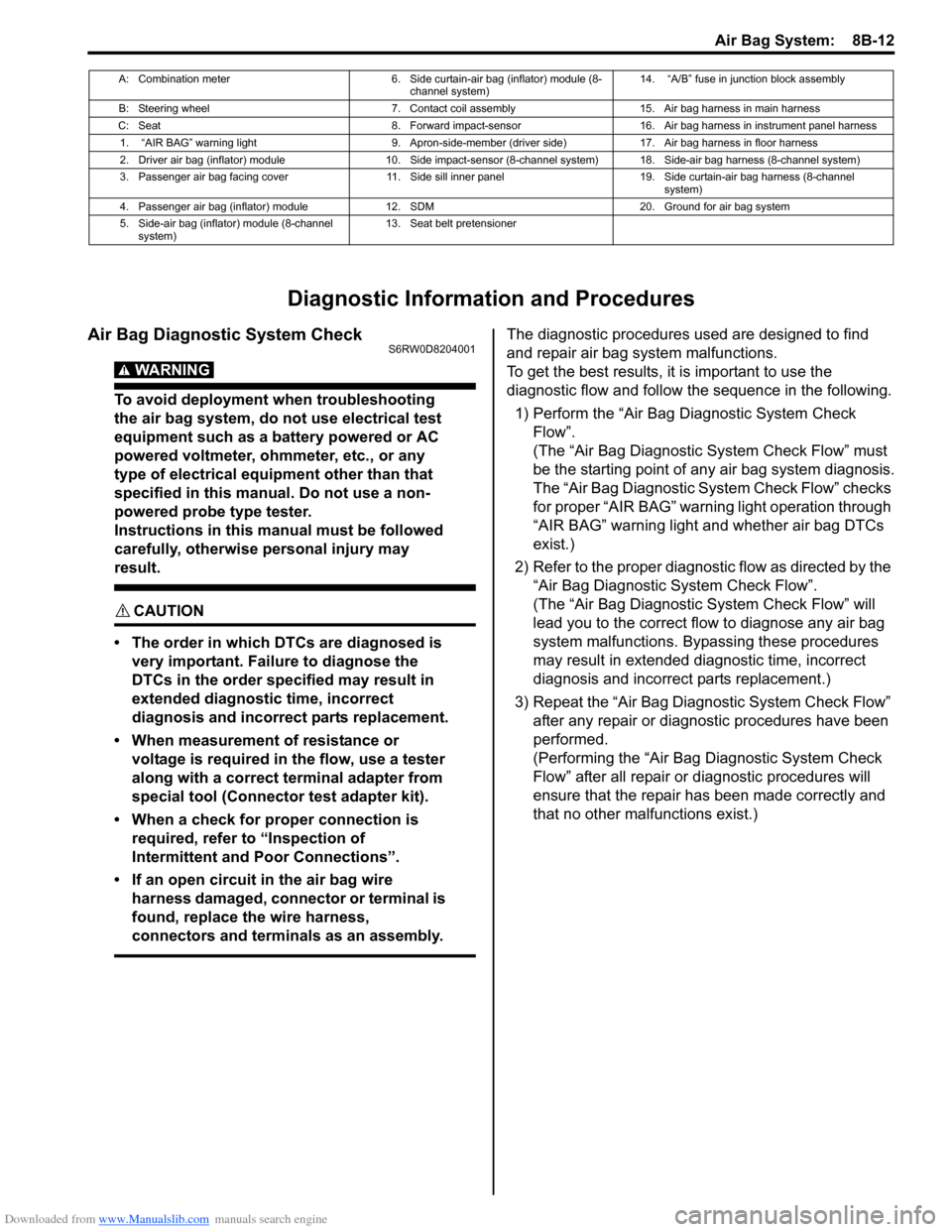
Downloaded from www.Manualslib.com manuals search engine Air Bag System: 8B-12
Diagnostic Information and Procedures
Air Bag Diagnostic System CheckS6RW0D8204001
WARNING!
To avoid deployment when troubleshooting
the air bag system, do not use electrical test
equipment such as a battery powered or AC
powered voltmeter, ohmmeter, etc., or any
type of electrical equipment other than that
specified in this manual. Do not use a non-
powered probe type tester.
Instructions in this manual must be followed
carefully, otherwise personal injury may
result.
CAUTION!
• The order in which DTCs are diagnosed is
very important. Failure to diagnose the
DTCs in the order specified may result in
extended diagnostic time, incorrect
diagnosis and incorrect parts replacement.
• When measurement of resistance or
voltage is required in the flow, use a tester
along with a correct terminal adapter from
special tool (Connector test adapter kit).
• When a check for proper connection is
required, refer to “Inspection of
Intermittent and Poor Connections”.
• If an open circuit in the air bag wire
harness damaged, connector or terminal is
found, replace the wire harness,
connectors and terminals as an assembly.
The diagnostic procedures used are designed to find
and repair air bag system malfunctions.
To get the best results, it is important to use the
diagnostic flow and follow the sequence in the following.
1) Perform the “Air Bag Diagnostic System Check
Flow”.
(The “Air Bag Diagnostic System Check Flow” must
be the starting point of any air bag system diagnosis.
The “Air Bag Diagnostic System Check Flow” checks
for proper “AIR BAG” warning light operation through
“AIR BAG” warning light and whether air bag DTCs
exist.)
2) Refer to the proper diagnostic flow as directed by the
“Air Bag Diagnostic System Check Flow”.
(The “Air Bag Diagnostic System Check Flow” will
lead you to the correct flow to diagnose any air bag
system malfunctions. Bypassing these procedures
may result in extended diagnostic time, incorrect
diagnosis and incorrect parts replacement.)
3) Repeat the “Air Bag Diagnostic System Check Flow”
after any repair or diagnostic procedures have been
performed.
(Performing the “Air Bag Diagnostic System Check
Flow” after all repair or diagnostic procedures will
ensure that the repair has been made correctly and
that no other malfunctions exist.)
A: Combination meter 6. Side curtain-air bag (inflator) module (8-
channel system)14. “A/B” fuse in junction block assembly
B: Steering wheel 7. Contact coil assembly 15. Air bag harness in main harness
C: Seat 8. Forward impact-sensor 16. Air bag harness in instrument panel harness
1. “AIR BAG” warning light 9. Apron-side-member (driver side) 17. Air bag harness in floor harness
2. Driver air bag (inflator) module 10. Side impact-sensor (8-channel system) 18. Side-air bag harness (8-channel system)
3. Passenger air bag facing cover 11. Side sill inner panel 19. Side curtain-air bag harness (8-channel
system)
4. Passenger air bag (inflator) module 12. SDM 20. Ground for air bag system
5. Side-air bag (inflator) module (8-channel
system)13. Seat belt pretensioner
Page 1070 of 1556
Downloaded from www.Manualslib.com manuals search engine 8B-31 Air Bag System:
NOTE
Upon completion of inspection and repair work, perform the following items.
• Reconnect all air bag system components and ensure all components are properly mounted.
• Repeat “Air Bag Diagnostic System Check” to confirm that the trouble has been corrected.
• Clear DTC B1157 (air bag deployed) of BCM referring to “DTC Clearance in Section 10B”, if any.
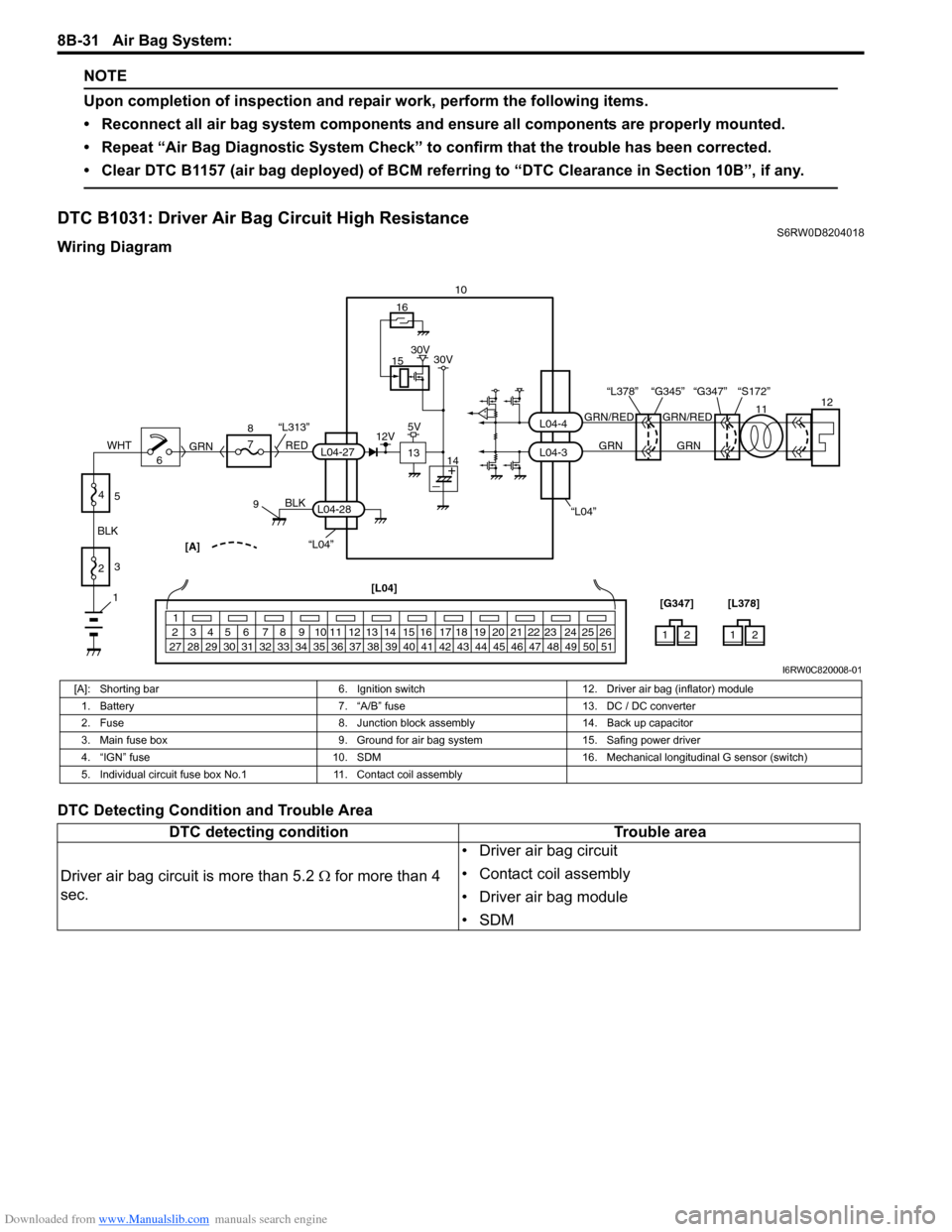
DTC B1031: Driver Air Bag Circuit High Resistance S6RW0D8204018
Wiring Diagram
DTC Detecting Condition and Trouble Area
“L04”“L04”[A]
BLK
L04-28
6 8
7
RED
GRN“L313”L04-27
910
L04-3 L04-4
1
2 3 4 5 6 7 8 9 10 11 12 13 14 15 16 17 18 19 20 21 22 23 24 25 26
27 28 29 30 31 32 33 34 35 36 37 38 39 40 41 42 43 44 45 46 47 48 49 50 51
12 [L04]
[G347]12 [L378]
15
13
16
12V5V30V 30V
141112
GRN/RED GRN/RED
GRN GRN
“G347” “S172” “L378” “G345”
1
2 BLKWHT3
4
5
I6RW0C820008-01
[A]: Shorting bar 6. Ignition switch 12. Driver air bag (inflator) module
1. Battery 7. “A/B” fuse 13. DC / DC converter
2. Fuse 8. Junction block assembly 14. Back up capacitor
3. Main fuse box 9. Ground for air bag system 15. Safing power driver
4. “IGN” fuse 10. SDM 16. Mechanical longitudinal G sensor (switch)
5. Individual circuit fuse box No.1 11. Contact coil assembly
DTC detecting condition Trouble area
Driver air bag circuit is more than 5.2 Ω for more than 4
sec.• Driver air bag circuit
• Contact coil assembly
• Driver air bag module
•SDM
Page 1071 of 1556
Downloaded from www.Manualslib.com manuals search engine Air Bag System: 8B-32
DTC Troubleshooting
Step Action Yes No
1Was “Air Bag Diagnostic System Check Flow” performed?Go to Step 2. Go to “Air Bag
Diagnostic System
Check Flow”.
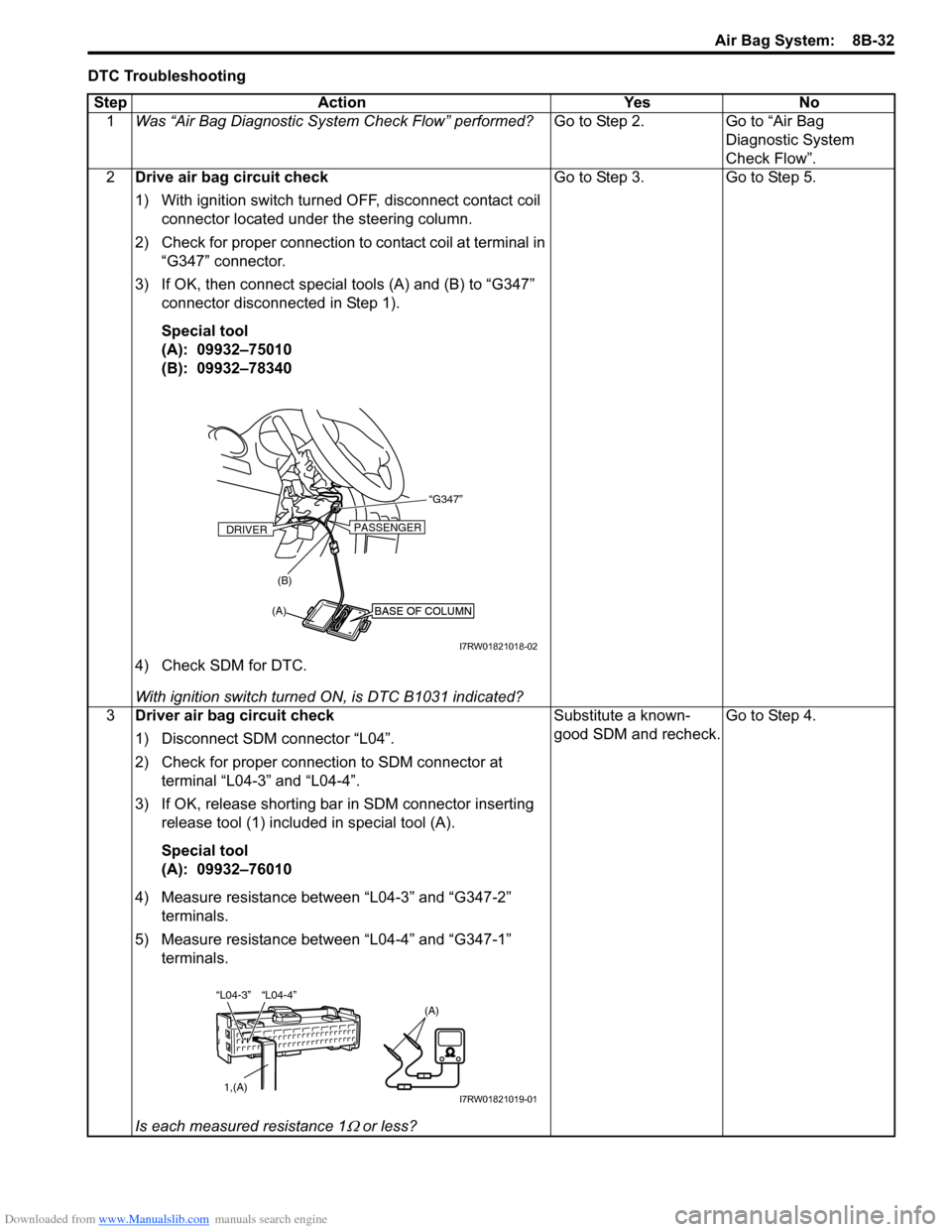
2Drive air bag circuit check
1) With ignition switch turned OFF, disconnect contact coil
connector located under the steering column.
2) Check for proper connection to contact coil at terminal in
“G347” connector.
3) If OK, then connect special tools (A) and (B) to “G347”
connector disconnected in Step 1).
Special tool
(A): 09932–75010
(B): 09932–78340
4) Check SDM for DTC.
With ignition switch turned ON, is DTC B1031 indicated?Go to Step 3. Go to Step 5.
3Driver air bag circuit check
1) Disconnect SDM connector “L04”.
2) Check for proper connection to SDM connector at
terminal “L04-3” and “L04-4”.
3) If OK, release shorting bar in SDM connector inserting
release tool (1) included in special tool (A).
Special tool
(A): 09932–76010
4) Measure resistance between “L04-3” and “G347-2”
terminals.
5) Measure resistance between “L04-4” and “G347-1”
terminals.
Is each measured resistance 1
Ω or less?Substitute a known-
good SDM and recheck.Go to Step 4.
BASE OF COLUMNBASE OF COLUMN
“G347”
(A)(B)
DRIVERPASSENGER
I7RW01821018-02
“L04-4” “L04-3”
1,(A)
(A)
I7RW01821019-01
Page 1072 of 1556
Downloaded from www.Manualslib.com manuals search engine 8B-33 Air Bag System:
NOTE
Upon completion of inspection and repair work, perform the following items.
• Reconnect all air bag system components and ensure all components are properly mounted.
• Clear DTCs referring to “DTC Clearance”, if any.
• Repeat “Air Bag Diagnostic System Check” to confirm that the trouble has been corrected.
DTC B1032: Driver Air Bag Circuit Low ResistanceS6RW0D8204019
Wiring Diagram
Refer to “DTC B1031: Driver Air Bag Circuit High Resistance”.
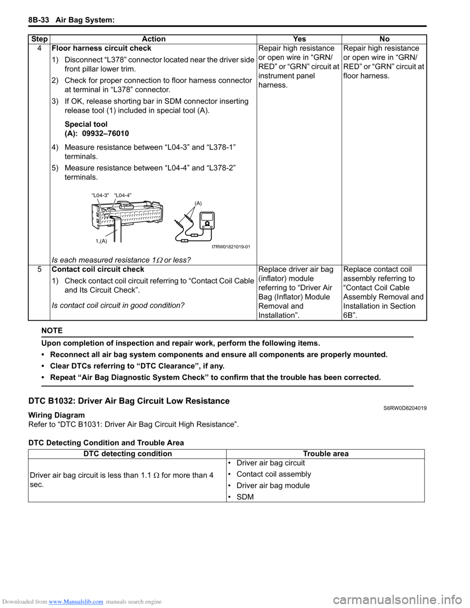
DTC Detecting Condition and Trouble Area4Floor harness circuit check
1) Disconnect “L378” connector located near the driver side
front pillar lower trim.
2) Check for proper connection to floor harness connector
at terminal in “L378” connector.
3) If OK, release shorting bar in SDM connector inserting
release tool (1) included in special tool (A).
Special tool
(A): 09932–76010
4) Measure resistance between “L04-3” and “L378-1”
terminals.
5) Measure resistance between “L04-4” and “L378-2”
terminals.
Is each measured resistance 1
Ω or less?Repair high resistance
or open wire in “GRN/
RED” or “GRN” circuit at
instrument panel
harness.Repair high resistance
or open wire in “GRN/
RED” or “GRN” circuit at
floor harness.
5Contact coil circuit check
1) Check contact coil circuit referring to “Contact Coil Cable
and Its Circuit Check”.
Is contact coil circuit in good condition?Replace driver air bag
(inflator) module
referring to “Driver Air
Bag (Inflator) Module
Removal and
Installation”.Replace contact coil
assembly referring to
“Contact Coil Cable
Assembly Removal and
Installation in Section
6B”. Step Action Yes No
“L04-4” “L04-3”
1,(A)
(A)
I7RW01821019-01
DTC detecting condition Trouble area
Driver air bag circuit is less than 1.1 Ω for more than 4
sec.• Driver air bag circuit
• Contact coil assembly
• Driver air bag module
•SDM
Page 1073 of 1556
Downloaded from www.Manualslib.com manuals search engine Air Bag System: 8B-34
DTC Troubleshooting
Step Action Yes No
1Was “Air Bag Diagnostic System Check Flow” performed?Go to Step 2. Go to “Air Bag
Diagnostic System
Check Flow”.
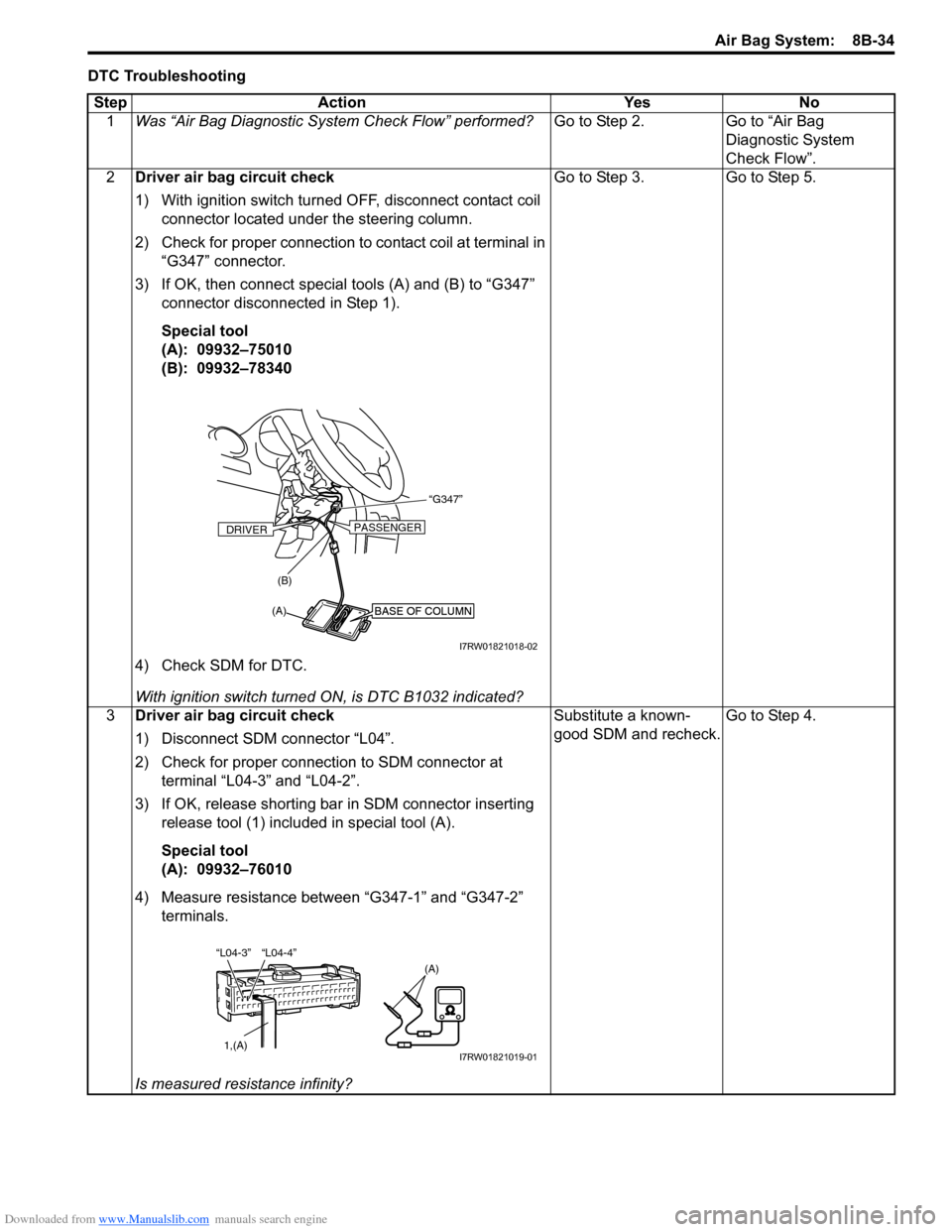
2Driver air bag circuit check
1) With ignition switch turned OFF, disconnect contact coil
connector located under the steering column.
2) Check for proper connection to contact coil at terminal in
“G347” connector.
3) If OK, then connect special tools (A) and (B) to “G347”
connector disconnected in Step 1).
Special tool
(A): 09932–75010
(B): 09932–78340
4) Check SDM for DTC.
With ignition switch turned ON, is DTC B1032 indicated?Go to Step 3. Go to Step 5.
3Driver air bag circuit check
1) Disconnect SDM connector “L04”.
2) Check for proper connection to SDM connector at
terminal “L04-3” and “L04-2”.
3) If OK, release shorting bar in SDM connector inserting
release tool (1) included in special tool (A).
Special tool
(A): 09932–76010
4) Measure resistance between “G347-1” and “G347-2”
terminals.
Is measured resistance infinity?Substitute a known-
good SDM and recheck.Go to Step 4.
BASE OF COLUMNBASE OF COLUMN
“G347”
(A)(B)
DRIVERPASSENGER
I7RW01821018-02
“L04-4” “L04-3”
1,(A)
(A)
I7RW01821019-01
Page 1074 of 1556
Downloaded from www.Manualslib.com manuals search engine 8B-35 Air Bag System:
NOTE
Upon completion of inspection and repair work, perform the following items.
• Reconnect all air bag system components and ensure all components are properly mounted.
• Clear DTCs referring to “DTC Clearance”, if any.
• Repeat “Air Bag Diagnostic System Check” to confirm that the trouble has been corrected.
DTC B1033: Driver Air Bag Circuit Shorted to GroundS6RW0D8204020
Wiring Diagram
Refer to “DTC B1031: Driver Air Bag Circuit High Resistance”.
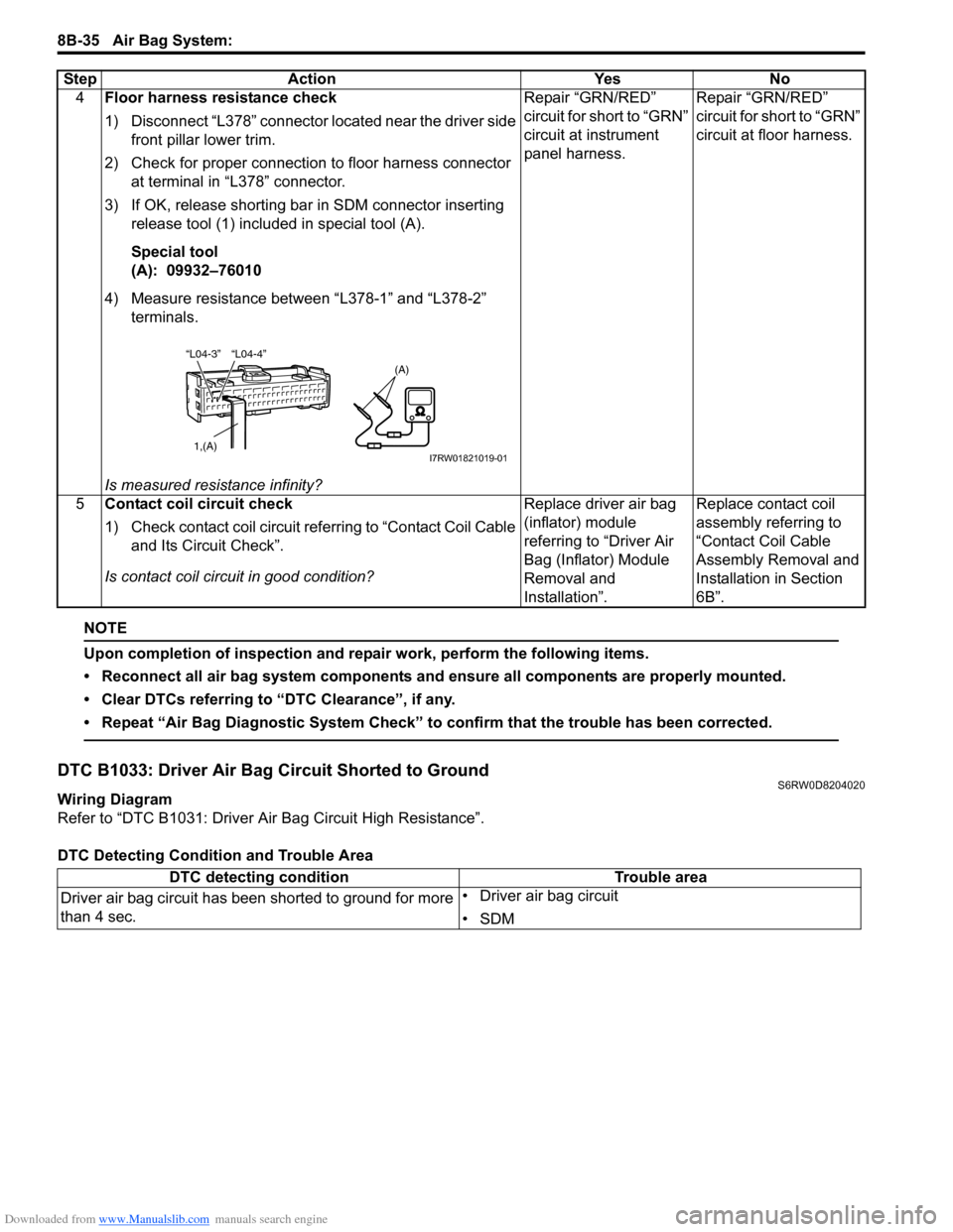
DTC Detecting Condition and Trouble Area4Floor harness resistance check
1) Disconnect “L378” connector located near the driver side
front pillar lower trim.
2) Check for proper connection to floor harness connector
at terminal in “L378” connector.
3) If OK, release shorting bar in SDM connector inserting
release tool (1) included in special tool (A).
Special tool
(A): 09932–76010
4) Measure resistance between “L378-1” and “L378-2”
terminals.
Is measured resistance infinity?Repair “GRN/RED”
circuit for short to “GRN”
circuit at instrument
panel harness.Repair “GRN/RED”
circuit for short to “GRN”
circuit at floor harness.
5Contact coil circuit check
1) Check contact coil circuit referring to “Contact Coil Cable
and Its Circuit Check”.
Is contact coil circuit in good condition?Replace driver air bag
(inflator) module
referring to “Driver Air
Bag (Inflator) Module
Removal and
Installation”.Replace contact coil
assembly referring to
“Contact Coil Cable
Assembly Removal and
Installation in Section
6B”. Step Action Yes No
“L04-4” “L04-3”
1,(A)
(A)
I7RW01821019-01
DTC detecting condition Trouble area
Driver air bag circuit has been shorted to ground for more
than 4 sec.• Driver air bag circuit
•SDM