2006 SUZUKI SX4 battery
[x] Cancel search: batteryPage 1048 of 1556
![SUZUKI SX4 2006 1.G Service Workshop Manual Downloaded from www.Manualslib.com manuals search engine 8B-9 Air Bag System:
Terminal arrangement of SDM (viewed from harness side)
[A]: Shorting bar 11. BCM 25. Driver seat belt pretensioner
[B]: C SUZUKI SX4 2006 1.G Service Workshop Manual Downloaded from www.Manualslib.com manuals search engine 8B-9 Air Bag System:
Terminal arrangement of SDM (viewed from harness side)
[A]: Shorting bar 11. BCM 25. Driver seat belt pretensioner
[B]: C](/manual-img/20/7612/w960_7612-1047.png)
Downloaded from www.Manualslib.com manuals search engine 8B-9 Air Bag System:
Terminal arrangement of SDM (viewed from harness side)
[A]: Shorting bar 11. BCM 25. Driver seat belt pretensioner
[B]: Connector 12. Combination meter 26. Passenger seat belt pretensioner
[C]: Junction block with BCM model 13. “AIR BAG” warning light27. Driver side-air bag (inflator) module (8-channel system)
[D]: Junction block without BCM model 14. Light driver 28. Passenger side-air bag (inflator) module (8-channel system)
1. Battery 15. SDM 29. Driver side curtain-air bag (inflator) module (8-channel
system)
2. Main fuse 16. To HVAC control module (auto A/C model) 30. Passenger side curtain-air bag (inflator) module (8-channel
system)
3. Fuse 17. Data link connector (DLC) 31. Safing power driver
4. Individual circuit fuse box No.1 18. Forward impact-sensor 32. X-Y-G (longitudinal / lateral acceleration)
5. “IGN” fuse 19. Driver side impact-sensor (8-channel
system)33. DC / DC converter
6. Ignition switch 20. Passenger side impact-sensor (8-channel
system)34. Mechanical longitudinal G sensor (switch)
7. Junction block assembly 21. Ground for air bag system 35. Back up capacitor
8. “DOME” fuse 22. Contact coil assembly
9. “METER” fuse 23. Driver air bag (inflator) module
10. “A/B” fuse 24. Passenger air bag (inflator) module
1
2 3 4 5 6 7 8 9 10 11 12 13 14 15 16 17 18 19 20 21 22 23 24 25 26
27 28 29 30 31 32 33 34 35 36 37 38 39 40 41 42 43 44 45 46 47 48 49 50 51
1
I7RW01822003-02
1. SDM Connector “L04”
Page 1051 of 1556
Downloaded from www.Manualslib.com manuals search engine Air Bag System: 8B-12
Diagnostic Information and Procedures
Air Bag Diagnostic System CheckS6RW0D8204001
WARNING!
To avoid deployment when troubleshooting
the air bag system, do not use electrical test
equipment such as a battery powered or AC
powered voltmeter, ohmmeter, etc., or any
type of electrical equipment other than that
specified in this manual. Do not use a non-
powered probe type tester.
Instructions in this manual must be followed
carefully, otherwise personal injury may
result.
CAUTION!
• The order in which DTCs are diagnosed is
very important. Failure to diagnose the
DTCs in the order specified may result in
extended diagnostic time, incorrect
diagnosis and incorrect parts replacement.
• When measurement of resistance or
voltage is required in the flow, use a tester
along with a correct terminal adapter from
special tool (Connector test adapter kit).
• When a check for proper connection is
required, refer to “Inspection of
Intermittent and Poor Connections”.
• If an open circuit in the air bag wire
harness damaged, connector or terminal is
found, replace the wire harness,
connectors and terminals as an assembly.
The diagnostic procedures used are designed to find
and repair air bag system malfunctions.
To get the best results, it is important to use the
diagnostic flow and follow the sequence in the following.
1) Perform the “Air Bag Diagnostic System Check
Flow”.
(The “Air Bag Diagnostic System Check Flow” must
be the starting point of any air bag system diagnosis.
The “Air Bag Diagnostic System Check Flow” checks
for proper “AIR BAG” warning light operation through
“AIR BAG” warning light and whether air bag DTCs
exist.)
2) Refer to the proper diagnostic flow as directed by the
“Air Bag Diagnostic System Check Flow”.
(The “Air Bag Diagnostic System Check Flow” will
lead you to the correct flow to diagnose any air bag
system malfunctions. Bypassing these procedures
may result in extended diagnostic time, incorrect
diagnosis and incorrect parts replacement.)
3) Repeat the “Air Bag Diagnostic System Check Flow”
after any repair or diagnostic procedures have been
performed.
(Performing the “Air Bag Diagnostic System Check
Flow” after all repair or diagnostic procedures will
ensure that the repair has been made correctly and
that no other malfunctions exist.)
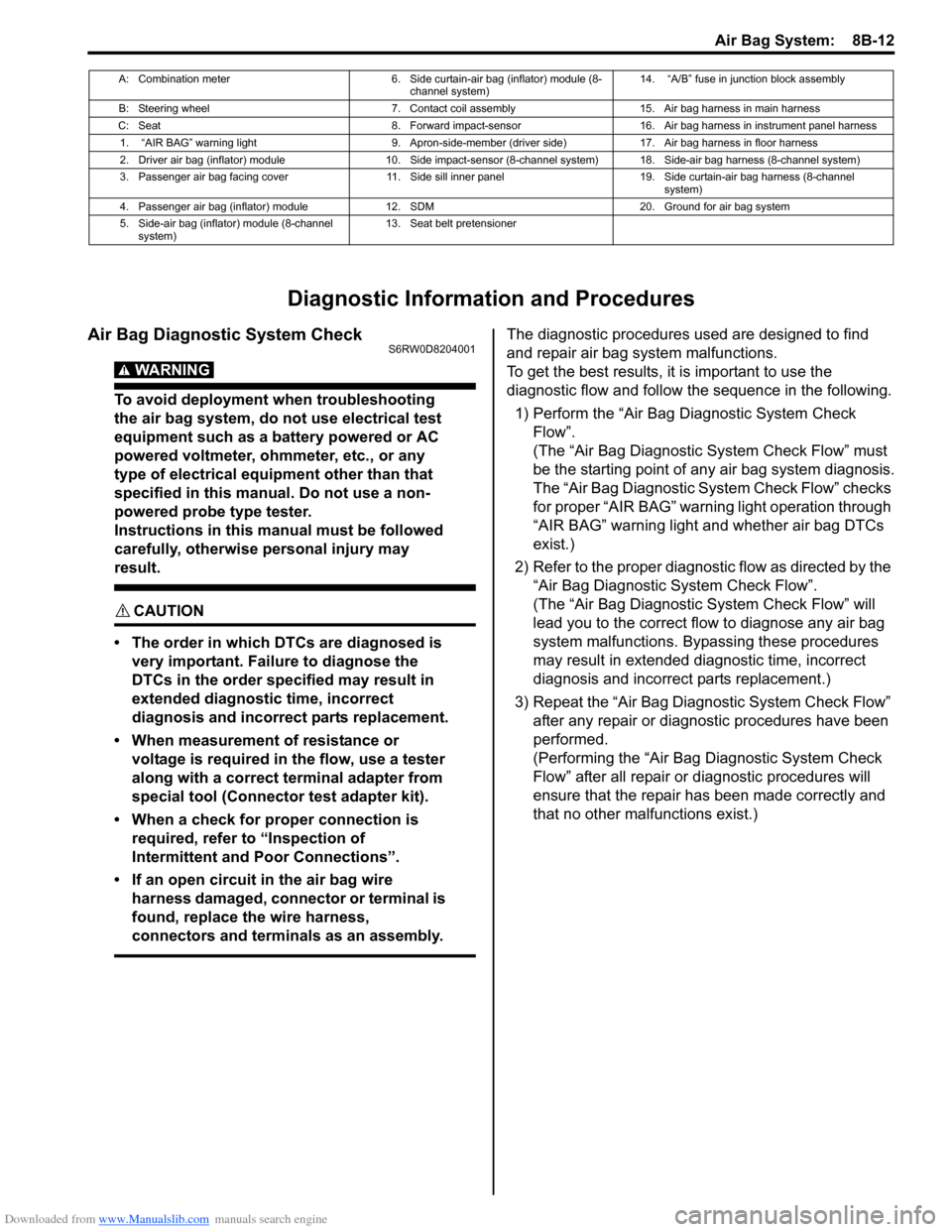
A: Combination meter 6. Side curtain-air bag (inflator) module (8-
channel system)14. “A/B” fuse in junction block assembly
B: Steering wheel 7. Contact coil assembly 15. Air bag harness in main harness
C: Seat 8. Forward impact-sensor 16. Air bag harness in instrument panel harness
1. “AIR BAG” warning light 9. Apron-side-member (driver side) 17. Air bag harness in floor harness
2. Driver air bag (inflator) module 10. Side impact-sensor (8-channel system) 18. Side-air bag harness (8-channel system)
3. Passenger air bag facing cover 11. Side sill inner panel 19. Side curtain-air bag harness (8-channel
system)
4. Passenger air bag (inflator) module 12. SDM 20. Ground for air bag system
5. Side-air bag (inflator) module (8-channel
system)13. Seat belt pretensioner
Page 1052 of 1556
Downloaded from www.Manualslib.com manuals search engine 8B-13 Air Bag System:
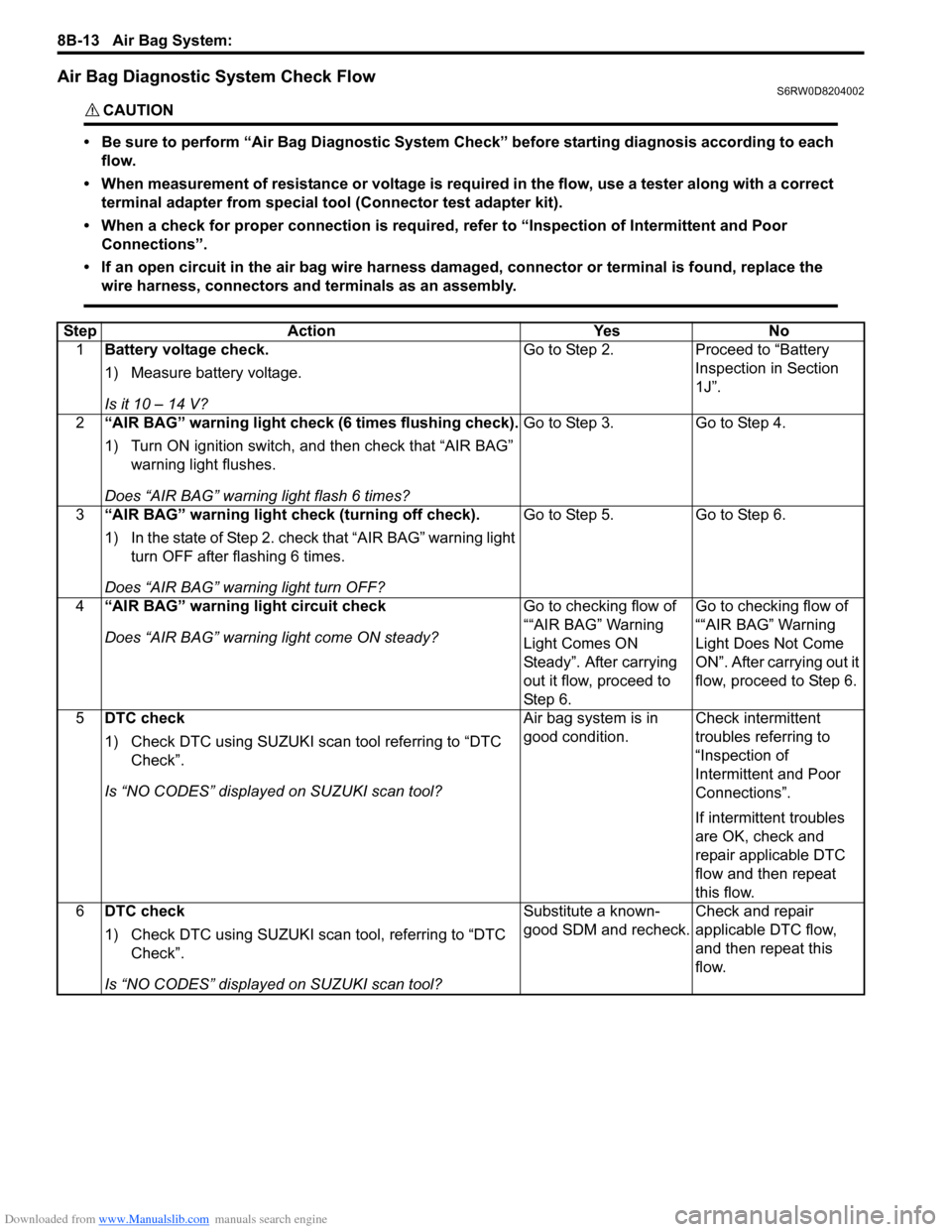
Air Bag Diagnostic System Check FlowS6RW0D8204002
CAUTION!
• Be sure to perform “Air Bag Diagnostic System Check” before starting diagnosis according to each
flow.
• When measurement of resistance or voltage is required in the flow, use a tester along with a correct
terminal adapter from special tool (Connector test adapter kit).
• When a check for proper connection is required, refer to “Inspection of Intermittent and Poor
Connections”.
• If an open circuit in the air bag wire harness damaged, connector or terminal is found, replace the
wire harness, connectors and terminals as an assembly.
Step Action Yes No
1Battery voltage check.
1) Measure battery voltage.
Is it 10 – 14 V?Go to Step 2. Proceed to “Battery
Inspection in Section
1J”.
2“AIR BAG” warning light check (6 times flushing check).
1) Turn ON ignition switch, and then check that “AIR BAG”
warning light flushes.
Does “AIR BAG” warning light flash 6 times?Go to Step 3. Go to Step 4.
3“AIR BAG” warning light check (turning off check).
1) In the state of Step 2. check that “AIR BAG” warning light
turn OFF after flashing 6 times.
Does “AIR BAG” warning light turn OFF?Go to Step 5. Go to Step 6.
4“AIR BAG” warning light circuit check
Does “AIR BAG” warning light come ON steady?Go to checking flow of
““AIR BAG” Warning
Light Comes ON
Steady”. After carrying
out it flow, proceed to
St ep 6 .Go to checking flow of
““AIR BAG” Warning
Light Does Not Come
ON”. After carrying out it
flow, proceed to Step 6.
5DTC check
1) Check DTC using SUZUKI scan tool referring to “DTC
Check”.
Is “NO CODES” displayed on SUZUKI scan tool?Air bag system is in
good condition.Check intermittent
troubles referring to
“Inspection of
Intermittent and Poor
Connections”.
If intermittent troubles
are OK, check and
repair applicable DTC
flow and then repeat
this flow.
6DTC check
1) Check DTC using SUZUKI scan tool, referring to “DTC
Check”.
Is “NO CODES” displayed on SUZUKI scan tool?Substitute a known-
good SDM and recheck.Check and repair
applicable DTC flow,
and then repeat this
flow.
Page 1057 of 1556
Downloaded from www.Manualslib.com manuals search engine Air Bag System: 8B-18
DTC CheckS6RW0D8204004
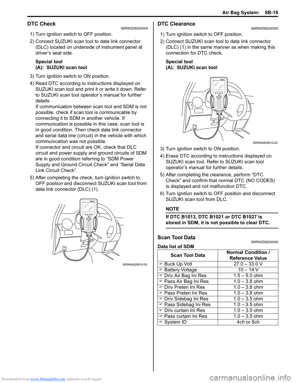
1) Turn ignition switch to OFF position.
2) Connect SUZUKI scan tool to data link connector
(DLC) located on underside of instrument panel at
driver’s seat side.
Special tool
(A): SUZUKI scan tool
3) Turn ignition switch to ON position.
4) Read DTC according to instructions displayed on
SUZUKI scan tool and print it or write it down. Refer
to SUZUKI scan tool operator’s manual for further
details.
If communication between scan tool and SDM is not
possible, check if scan tool is communicable by
connecting it to SDM in another vehicle. If
communication is possible in this case, scan tool is
in good condition. Then check data link connector
and serial data line (circuit) in the vehicle with which
communication was not possible.
If connector and circuit are OK, check that DLC
circuit and power supply and ground circuits of SDM
are in good condition referring to “SDM Power
Supply and Ground Circuit Check” and “Serial Data
Link Circuit Check”.
5) After completing the check, turn ignition switch to
OFF position and disconnect SUZUKI scan tool from
data link connector (DLC) (1).
DTC ClearanceS6RW0D8204005
1) Turn ignition switch to OFF position.
2) Connect SUZUKI scan tool to data link connector
(DLC) (1) in the same manner as when making this
connection for DTC check.
Special tool
(A): SUZUKI scan tool
3) Turn ignition switch to ON position.
4) Erase DTC according to instructions displayed on
SUZUKI scan tool. Refer to SUZUKI scan tool
operator’s manual for further details.
5) After completing the clearance, perform “DTC
Check” and confirm that normal DTC (NO CODES)
is displayed and not malfunction DTC.
6) Turn ignition switch to OFF position and disconnect
SUZUKI scan tool from DLC.
NOTE
If DTC B1013, DTC B1021 or DTC B1027 is
stored in SDM, it is not possible to clear DTC.
Scan Tool DataS6RW0D8204006
Data list of SDM
I5RW0A820010-03
Scan Tool DataNormal Condition /
Reference Value
�) Buck Up Volt 27.0 – 33.0 V
�) Battery Voltage 10 – 14 V
�) Driv Air Bag Ini Res 1.5 – 5.0 ohm
�) Pass Air Bag Ini Res 1.0 – 3.8 ohm
�) Driv Preten Ini Res 1.0 – 3.8 ohm
�) Pass Preten Ini Res 1.0 – 3.8 ohm
�) Driv Sidebag Ini Res 1.0 – 3.5 ohm
�) Pass Sidebag Ini Res 1.0 – 3.5 ohm
�) Driv curtain Ini Res 1.0 – 3.5 ohm
�) Pass curtain Ini Res 1.0 – 3.5 ohm
�) System ID 4ch or 8ch
I5RW0A820010-03
Page 1058 of 1556
Downloaded from www.Manualslib.com manuals search engine 8B-19 Air Bag System:
Scan Tool Data Definition
Buck Up Volt (V)
This parameter indicates the capacity of the backup
capacitor installed to maintain the ignition current (as
much as possible) even when the power supply to SDM
that ignites the inflator is shut off.
Battery Voltage (V)
Battery voltage is an analog input signal read by SDM.
Dirv Air Bag Ini Res (Driver air bag initiator
resistance) (ohm)
This parameter indicates the resistance of the driver air
bag initiator circuit.
Pass Air Bag Ini Res (Passenger air bag initiator
resistance) (ohm)
This parameter indicates the resistance of the passenger
air bag initiator circuit.
Driv Preten Ini Res (Driver pretensioner initiator
resistance) (ohm)
This parameter indicates the resistance of the driver seat
belt pretensioner initiator circuit.Pass Preten Ini Res (Passenger pretensioner
initiator resistance) (ohm)
This parameter indicates the resistance of the passenger
seat belt pretensioner initiator circuit.
Driv Sidebag Ini Res (Driver side-air bag initiator
resistance) (ohm)
This parameter indicates the resistance of the driver
side-air bag initiator circuit.
Pass Sidebag Ini Res (Passenger side-air bag
initiator resistance) (ohm)
This parameter indicates the resistance of the passenger
side-air bag initiator circuit.
Driv curtain Ini RES (Driver side curtain-air bag
initiator resistance) (ohm)
This parameter indicates the resistance of the driver side
curtain-air bag initiator circuit.
Pass curtain Ini RES (Passenger side curtain-air bag
initiator resistance) (ohm)
This parameter indicates the resistance of the passenger
side curtain-air bag initiator circuit.
System ID (4ch/8ch)
This parameter indicates the number of initiator circuits.
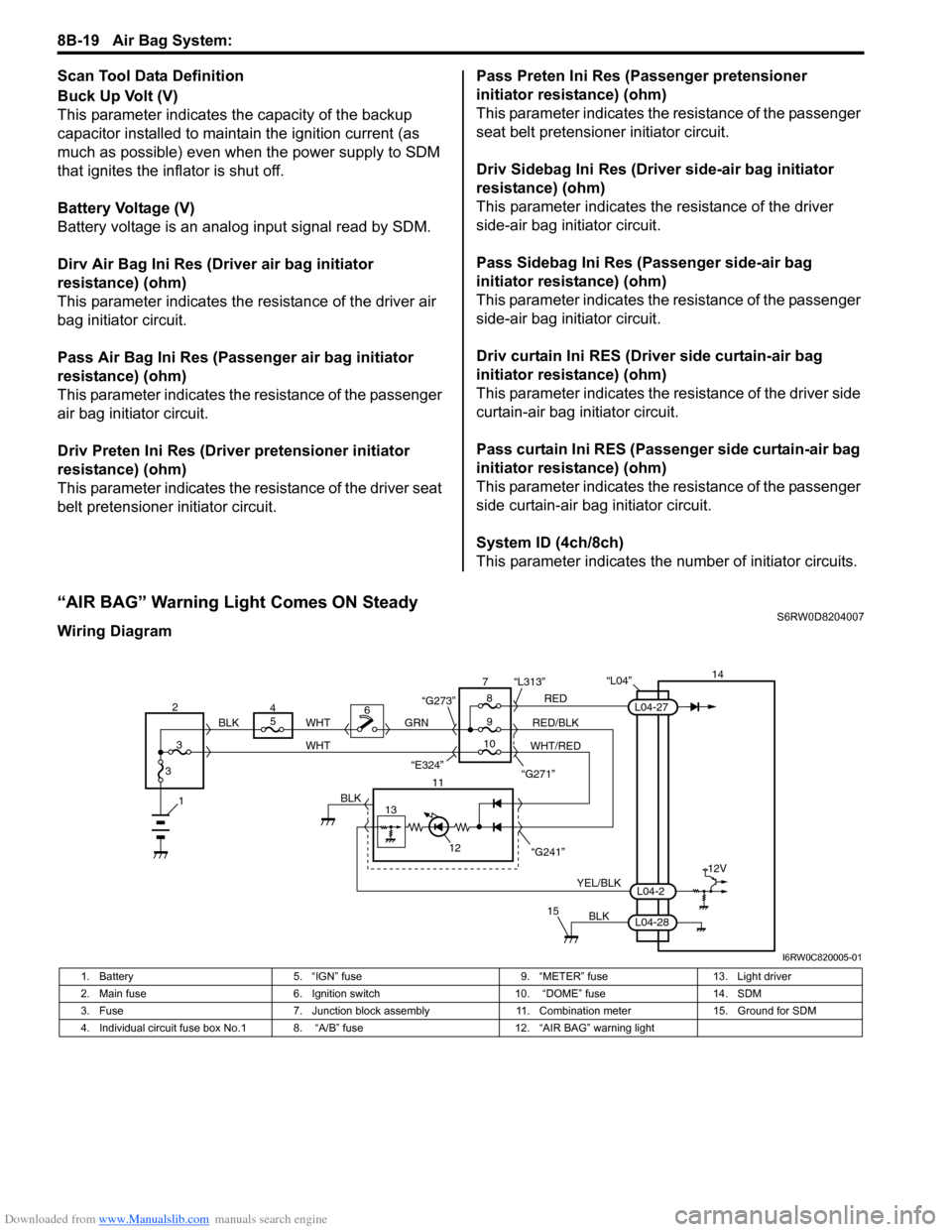
“AIR BAG” Warning Light Comes ON SteadyS6RW0D8204007
Wiring Diagram
“L04”14
5
9RED
RED/BLK GRN
YEL/BLK
BLK
8 7
11
12
15
L04-2
L04-28
L04-27
“G241” “G271” “L313”
13
12V
6
1BLK
WHT WHT
WHT/RED 2
34
310 BLK
“G273”
“E324”
I6RW0C820005-01
1. Battery 5. “IGN” fuse 9. “METER” fuse 13. Light driver
2. Main fuse 6. Ignition switch 10. “DOME” fuse 14. SDM
3. Fuse 7. Junction block assembly 11. Combination meter 15. Ground for SDM
4. Individual circuit fuse box No.1 8. “A/B” fuse 12. “AIR BAG” warning light
Page 1062 of 1556
Downloaded from www.Manualslib.com manuals search engine 8B-23 Air Bag System:
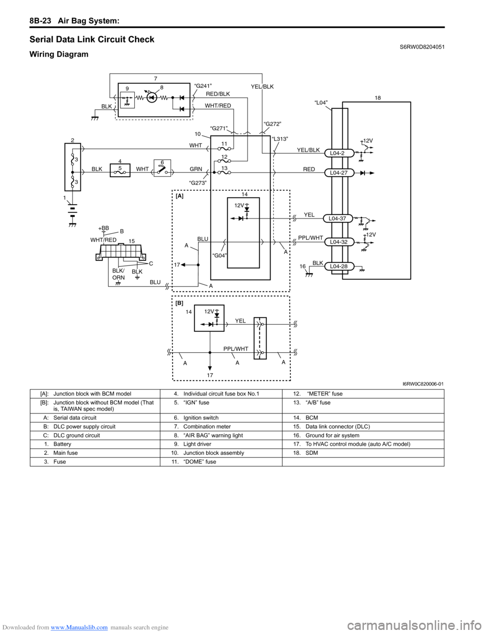
Serial Data Link Circuit CheckS6RW0D8204051
Wiring Diagram
1
2
3
3
18
12V
RED 7
14 9
10
“L313”
“G273”
YEL/BLKL04-2
L04-27 “L04”
PPL/WHT
“G04”L04-3212V
8
GRN
15
+BB
56WHTWHT
4
BLUBLU
BLK
16
11
12
“G241”
13
BLK
L04-28
RED/BLK
WHT/REDYEL/BLK
BLK“G271”
“G272”
WHT/RED
BLK/
ORNBLK
B
C
A A
A
17
[A]
A
[B]
12V
PPL/WHTYEL14
17A
A
YELL04-37
12V
I6RW0C820006-01
[A]: Junction block with BCM model 4. Individual circuit fuse box No.1 12. “METER” fuse
[B]: Junction block without BCM model (That
is, TAIWAN spec model)5. “IGN” fuse 13. “A/B” fuse
A: Serial data circuit 6. Ignition switch 14. BCM
B: DLC power supply circuit 7. Combination meter 15. Data link connector (DLC)
C: DLC ground circuit 8. “AIR BAG” warning light 16. Ground for air system
1. Battery 9. Light driver 17. To HVAC control module (auto A/C model)
2. Main fuse 10. Junction block assembly 18. SDM
3. Fuse 11. “DOME” fuse
Page 1065 of 1556
Downloaded from www.Manualslib.com manuals search engine Air Bag System: 8B-26
DTC B1014: “AIR BAG” Warning Light CircuitS6RW0D8204011
Wiring Diagram
Refer to““AIR BAG” Warning Light Comes ON Steady”.
DTC Detecting Condition and Trouble Area
DTC Troubleshooting
NOTE
Upon completion of inspection and repair work, perform the following items.
• Reconnect all air bag system components and ensure all components are properly mounted.
• Clear DTCs referring to “DTC Clearance”, if any.
• Repeat “Air Bag Diagnostic System Check” to confirm that the trouble has been corrected.
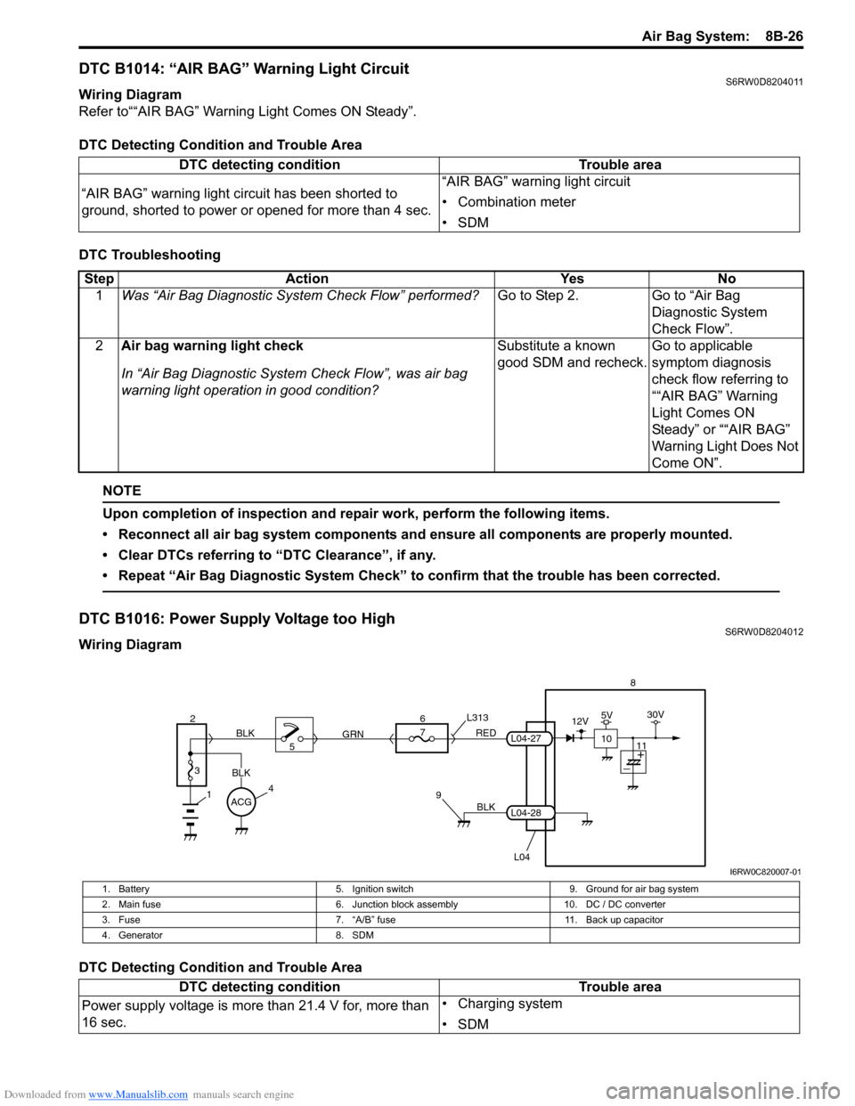
DTC B1016: Power Supply Voltage too HighS6RW0D8204012
Wiring Diagram
DTC Detecting Condition and Trouble AreaDTC detecting condition Trouble area
“AIR BAG” warning light circuit has been shorted to
ground, shorted to power or opened for more than 4 sec.“AIR BAG” warning light circuit
• Combination meter
•SDM
Step Action Yes No
1Was “Air Bag Diagnostic System Check Flow” performed?Go to Step 2. Go to “Air Bag
Diagnostic System
Check Flow”.
2Air bag warning light check
In “Air Bag Diagnostic System Check Flow”, was air bag
warning light operation in good condition?Substitute a known
good SDM and recheck.Go to applicable
symptom diagnosis
check flow referring to
““AIR BAG” Warning
Light Comes ON
Steady” or ““AIR BAG”
Warning Light Does Not
Come ON”.
BLK
L04
7
RED
GRN L313
98
L04-28
L04-27
1
2
3
BLK
45 BLK6
ACG
10
12V5V30V
11
I6RW0C820007-01
1. Battery 5. Ignition switch 9. Ground for air bag system
2. Main fuse 6. Junction block assembly 10. DC / DC converter
3. Fuse 7. “A/B” fuse 11. Back up capacitor
4. Generator 8. SDM
DTC detecting condition Trouble area
Power supply voltage is more than 21.4 V for, more than
16 sec.• Charging system
•SDM
Page 1066 of 1556
Downloaded from www.Manualslib.com manuals search engine 8B-27 Air Bag System:
DTC Troubleshooting
NOTE
Upon completion of inspection and repair work, perform the following items.
• Reconnect all air bag system components and ensure all components are properly mounted.
• Clear DTCs referring to “DTC Clearance”, if any.
• Repeat “Air Bag Diagnostic System Check” to confirm that the trouble has been corrected.
DTC B1017: Power Supply Voltage too LowS6RW0D8204013
Wiring Diagram
Refer to “DTC B1016: Power Supply Voltage too High”.
DTC Detecting Condition and Trouble AreaStep Action Yes No
1Was “Air Bag Diagnostic System Check Flow” performed?Go to Step 2. Go to “Air Bag
Diagnostic System
Check Flow”.
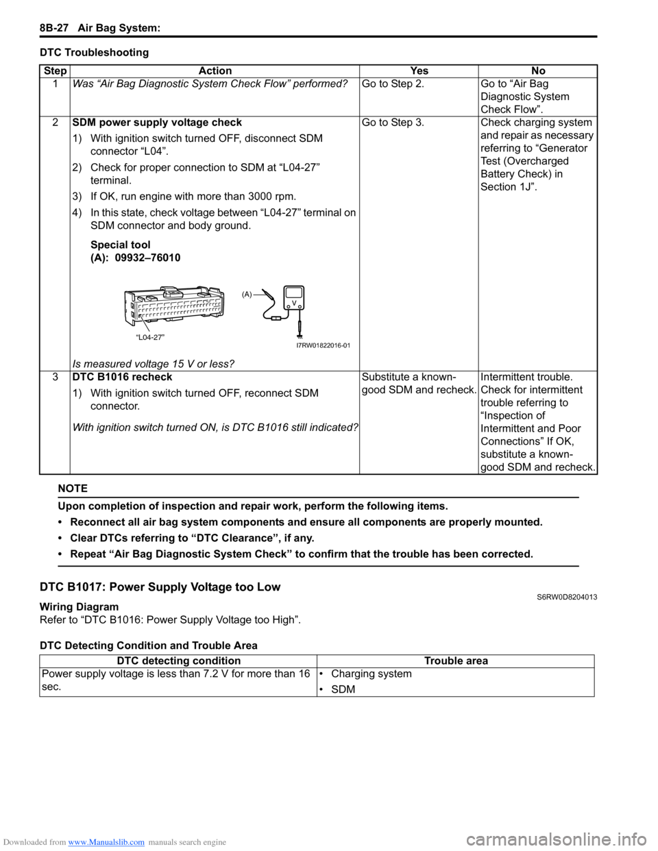
2SDM power supply voltage check
1) With ignition switch turned OFF, disconnect SDM
connector “L04”.
2) Check for proper connection to SDM at “L04-27”
terminal.
3) If OK, run engine with more than 3000 rpm.
4) In this state, check voltage between “L04-27” terminal on
SDM connector and body ground.
Special tool
(A): 09932–76010
Is measured voltage 15 V or less?Go to Step 3. Check charging system
and repair as necessary
referring to “Generator
Test (Overcharged
Battery Check) in
Section 1J”.
3DTC B1016 recheck
1) With ignition switch turned OFF, reconnect SDM
connector.
With ignition switch turned ON, is DTC B1016 still indicated?Substitute a known-
good SDM and recheck.Intermittent trouble.
Check for intermittent
trouble referring to
“Inspection of
Intermittent and Poor
Connections” If OK,
substitute a known-
good SDM and recheck.
“L04-27”
(A)
I7RW01822016-01
DTC detecting condition Trouble area
Power supply voltage is less than 7.2 V for more than 16
sec.• Charging system
•SDM